 Ahmed Azouz
Step 1: Material

The main material is MDF wood and I used 2mm for the structure and 4mm for the base.
Blueprints are available to download in the last step, you have to print the pattern then glue it directly to MDF.
Cut along with the outlines and drill holes. I used Rotary tool to drill and cut the wood, And for the base I don't have blueprints but I think you can improvise.
Step 2: Painting and Styling

To give the project an attractive look I used the same blueprints then I designed a cover using Photoshop to create some decals and geometric shapes to look realistic, then I glue it on wood using white glue.
Step 3: Frame Assembling

This robotic arm was simple to assemble because everything was planned ahead ago so its simply fix the servo motors in place with screws, and while working I've made minor tweaks to be done.
Then to attach the right and left side I used thick wooden sticks and glue it using super glue instate of long screws to reduce the wight.
Step 4: Gripper (Pinch Mechanism)

I Bend a two metal rod by pliers then I drill a hall inside a piece of wood 3 mm thick using Rotary tool drill and glue it by super glue.
Step 5: Making Base

Base is made from 4 mm thick MDF wood, I cut square approx 17cm * 10cm with table saw then drill a hall to sit the base servo motor 9g. to reduce the friction between base and cylinder I cut a part of strong cardboard can 2.5cm height & 10cm Diameter, then I drill it also to attach the servo motor shaft.
Step 6: Electronics

When using more than two servos with Arduino you must use an external power source for them, and in this project I used three micro servos 9g and one big servo motor.
Of course the first demonstration test was virtual on tinkercad.com to simulate the servos and test the electric circuit.
So in this case I used 4 batteries AA 1.5 v that equals 6 v, then I made breadboard test setup and after that I made very simple expansion dock for Arduino nano.
Step 7: Automation Application

Actually this is my favorite part is to automate an Arduino project using PC, In my opinion it was a good start to learn how to improve the capabilities of controlling the board and any other project in the future.
Reaching to a fixed angles positions wasn't easy to do, So at the beginning I solved this problem by using a third party Application named "Processing 3". In the initial stages I made a supported interface that simulate the Robot arm servos (Base, Shoulder, Elbow and Gripper) by keyboard and move them separately "angle by angle" until it reached to a fixed position prepared previously.
Then when it reached to that prepared position I record these four angles in Array of code (A,B,C,D), Then I used these multi Arrays later on in my Windows Application,It helped me a lot to know the limits of each servo motor angles each in its place.
These collected limits I put it as guideline into user interface sidebars to keep the ARM under control and also to support the playback function.
by using this application your able to control, record , monitoring the Robot Arm as following:
1. Motion Control:
There is two moods to control this robot arm, first is manual by dragging the track bars that controls a spastic servo such as
Gripper: click open & close button to open and close the robot gripper.
Base: Drag the the tracking bar right & left or even use keyboard arrows (right/left) to move the base right and left.
Shoulder: Drag the the tracking bar right & left or even use keyboard arrows (up/down) to move the shoulder Up and Down
Elbow: Drag the the tracking bar right & left or even use keyboard keys (w/s) to move the elbow motor Up and Down
2. Motion Record:
Once you want to automate the movement of the robot arm you have to record the position in every step by clicking "Rec. Position" Button or press (R) in keyboard, Then the application will take care about it.
In...
Read more »
 Mario Ninic
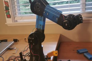
 Mattias
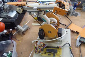
 Rue Mohr
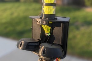
 Peter Sinclair
how does app works?
any links to download it.