 Michele Perla
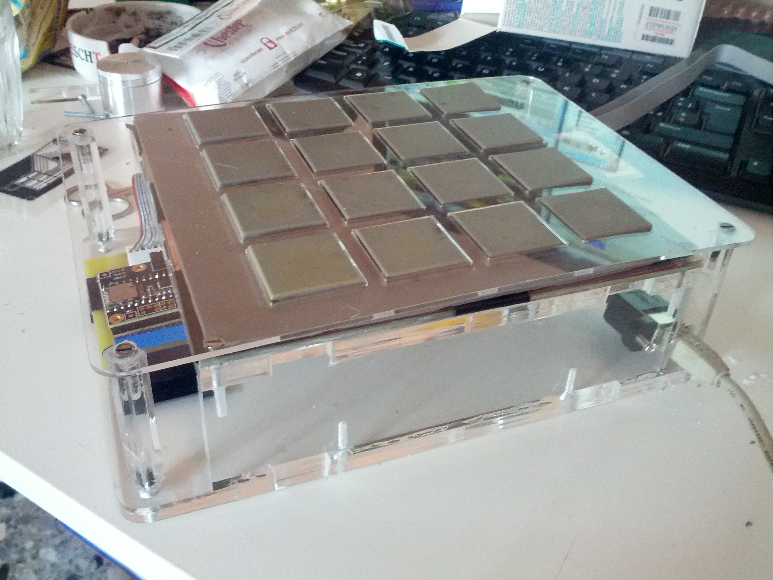
I'm a musician and I needed a simple and effective instrument to create drum beats without having to manually write them note by note. I also wanted something fairly small, that could easily sit on my desktop while embracing my guitar and that could be used even at late night without making too much drumming noise. An MPC style MIDI controller perfectly suits my needs.
There are a lot of DIY MIDI controllers of this kind around, but most of them use simple on/off tactile buttons, which is not enough for me. I want to have a fairly reliable velocity control because I will mainly use this with real-life drums simulation. Therefore the only reliable approach is to use Force Sensing Resistors as tactile sensors; the thing is, commercial FSRs are NOT CHEAP! Really, 8 bucks a piece is way too much for me, considering that I want a 4x4 matrix that's more than 120 bucks, which is more than the price of a ready-made MPC style MIDI controller. No deal.
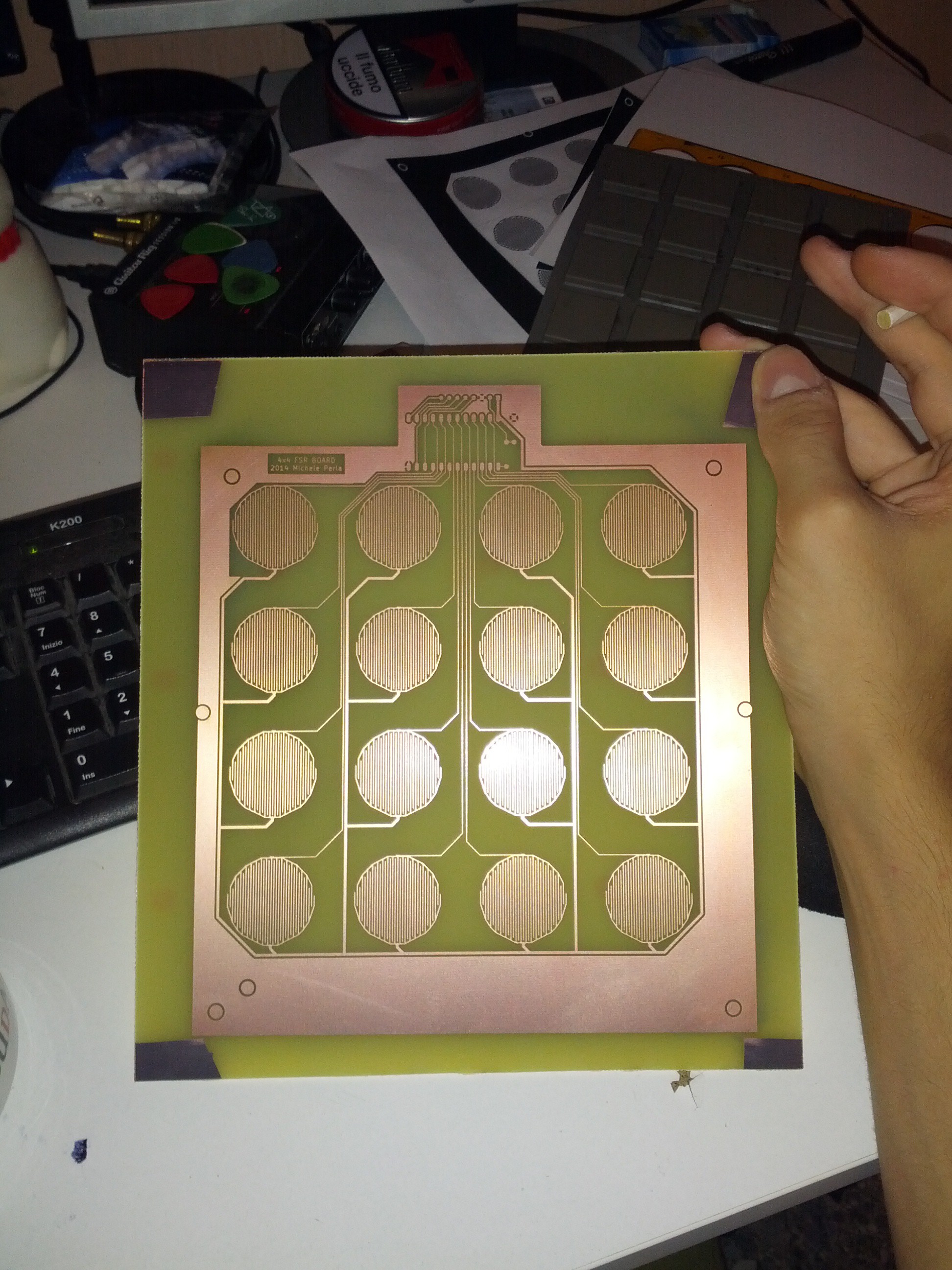
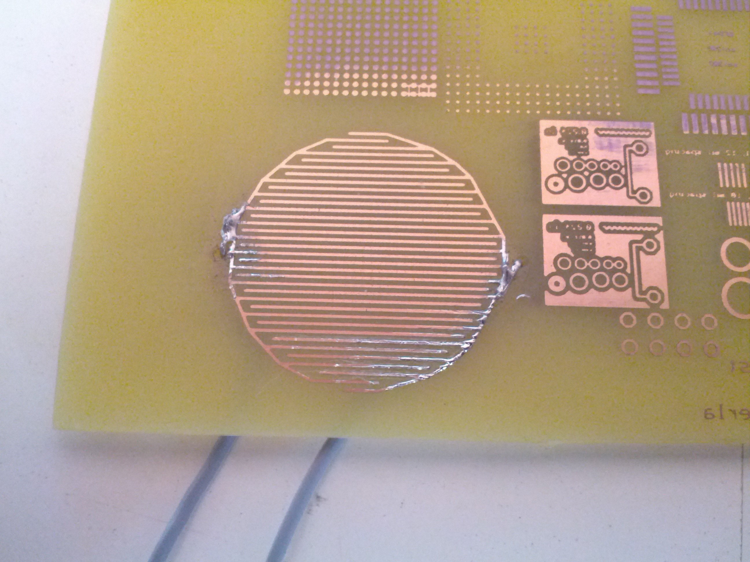
Thankfully, I found out that these FSRs are usually made of a thin film of a material that varies its resistivity when under pressure, called Velostat, and this film is sandwiched between two copper contacts; alternatively, they can be made using a layer of two intricated copper traces and a velostat layer spaced from the first one (just like te PCB button pads found in any game controller).
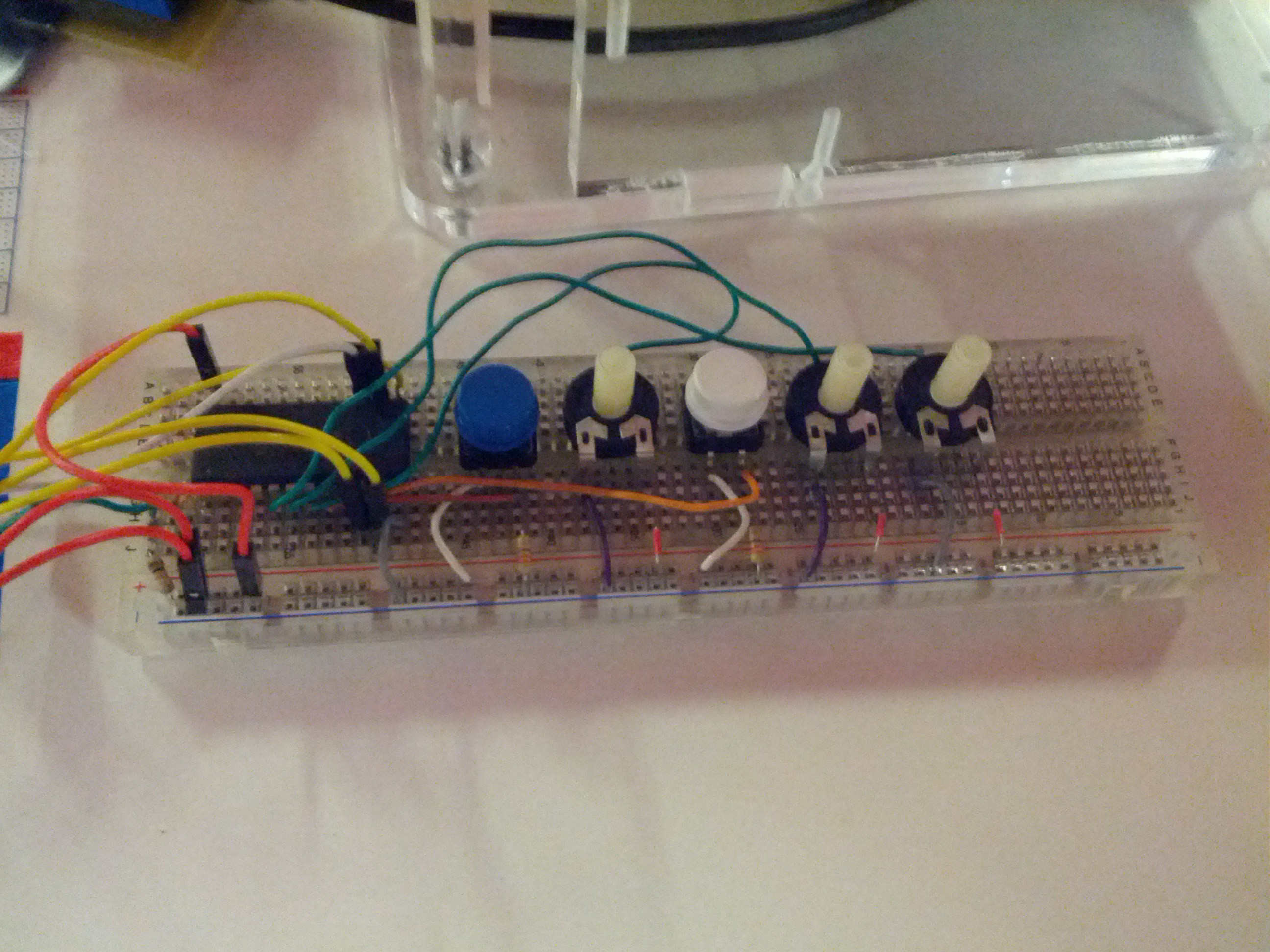
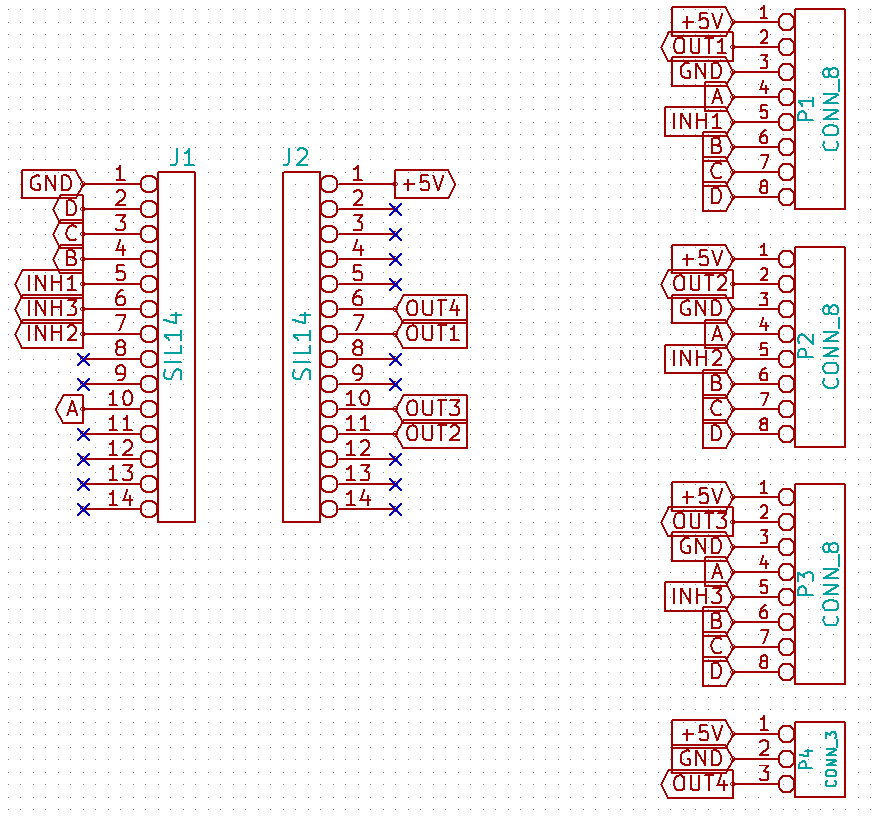
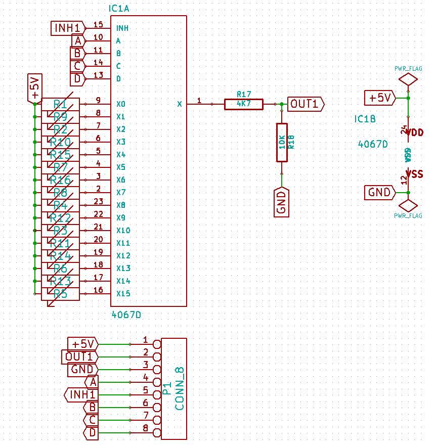
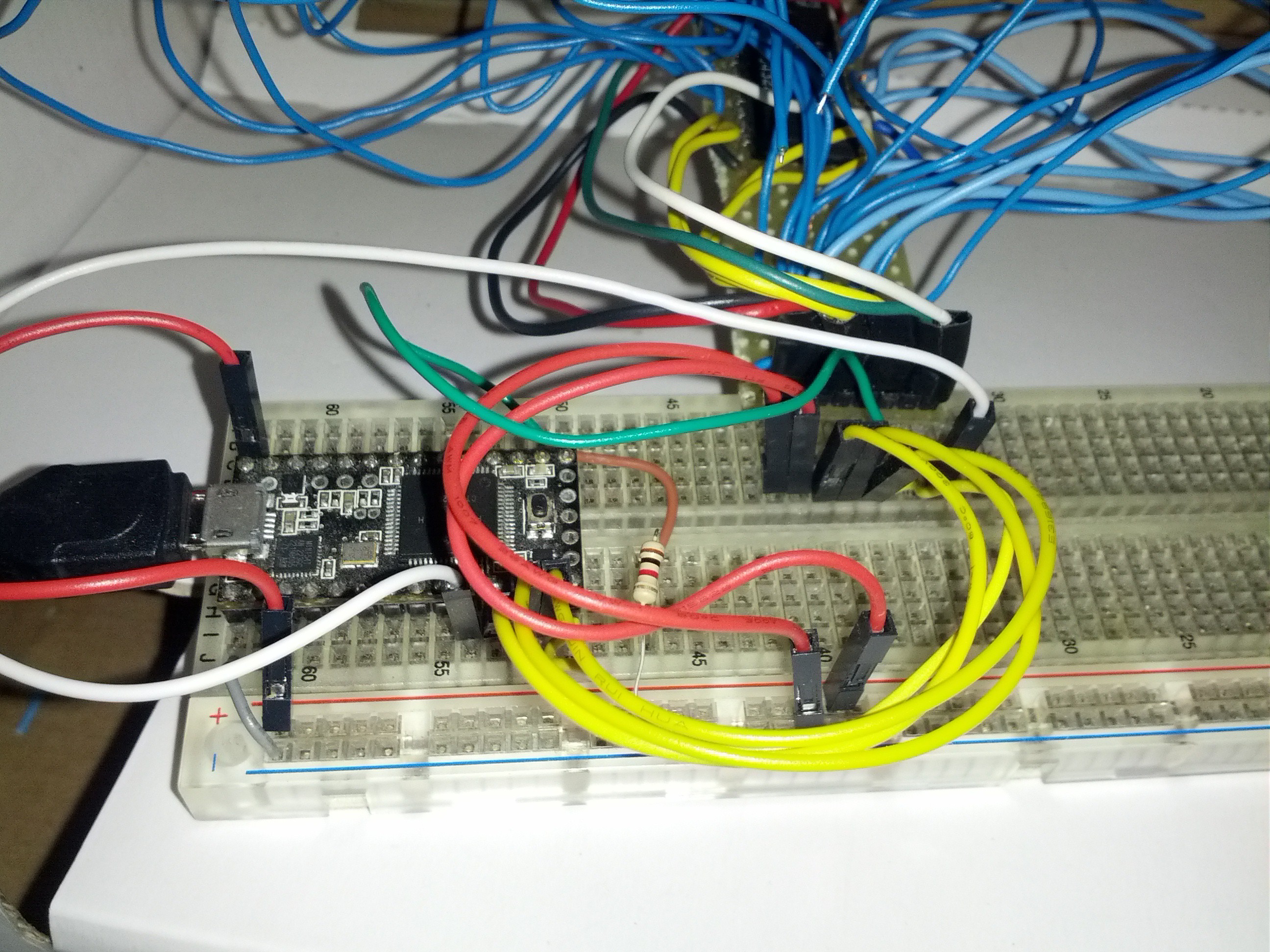
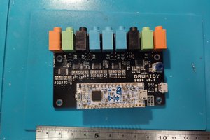
To connect the FSRs to the microcontroller I use a 16 channels multiplexer to scan through all the FSRs and which puts each FSR as the first resistor of a voltage divider; the FSR decreases its impedance with pressure, therefore I read the voltage drop across a fixed resistor which is high when fully pressed and low when barely pressed.
Finally, I keep track of the current status of each FSR which can be on or off to trigger a MIDI note on/off signal via USB.
Stay in touch for more details ;)

 Evgeny
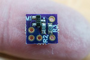
 Bud Bennett
 ThunderSqueak
 sjm4306
you should commercialize this project. Form a company. Borrow some funds