 agp.cooper
The First SCARA Prototype
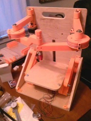
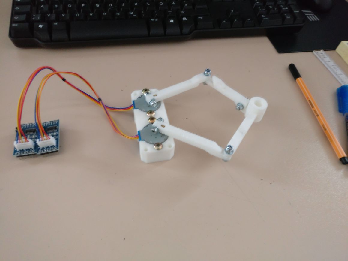
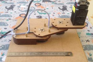
Here is my first prototype:
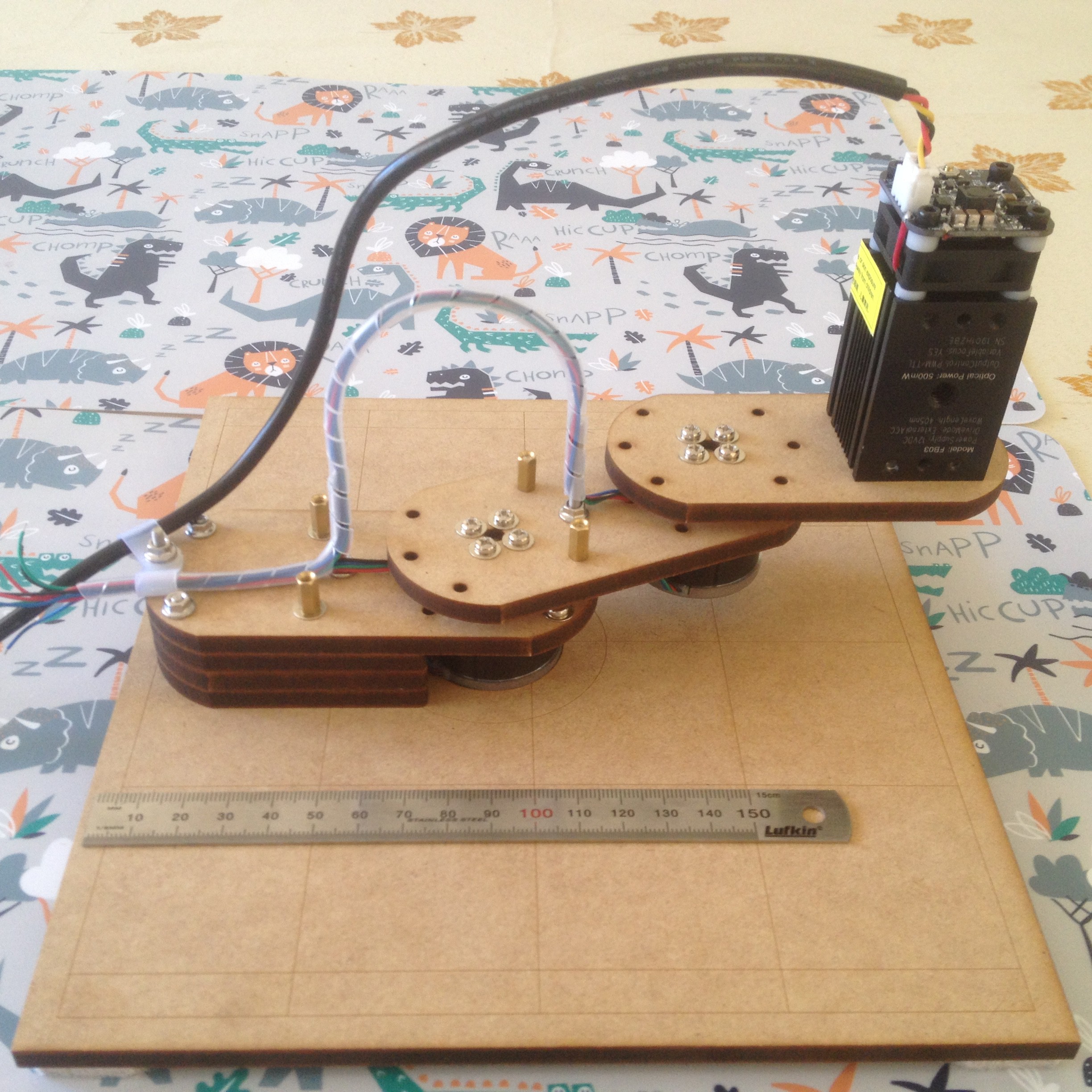
The arms are 100 mm and 60 mm resulting in a 2 to 1 working area of 160mm wide by 80 mm high.
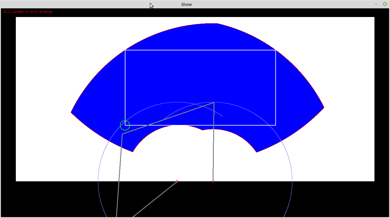
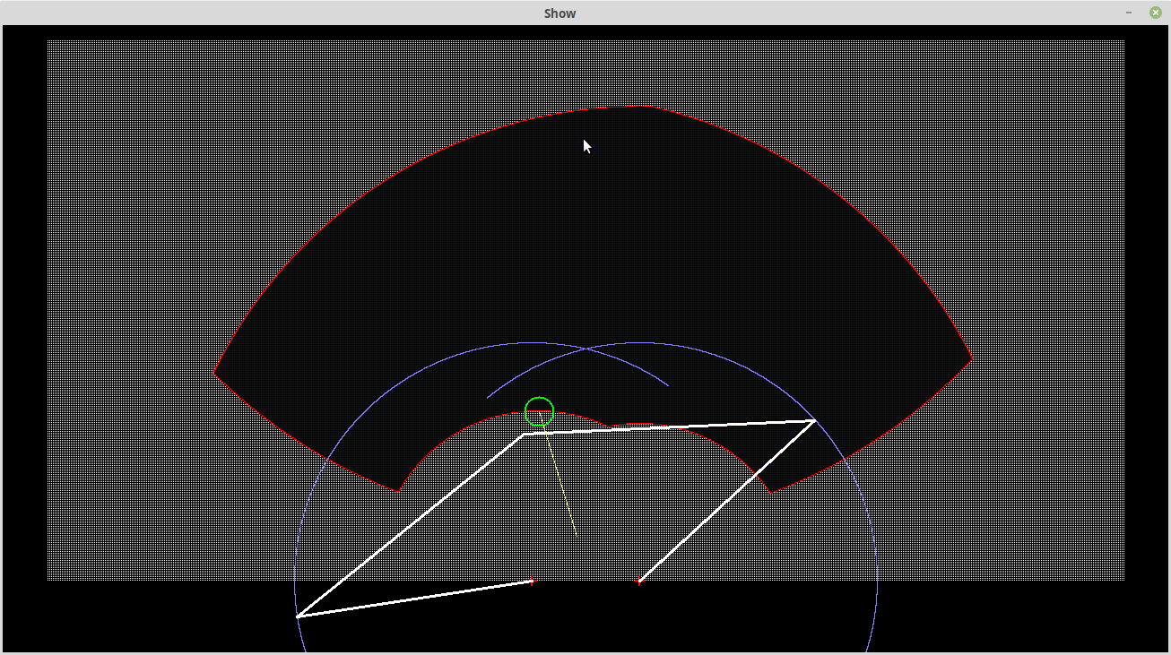
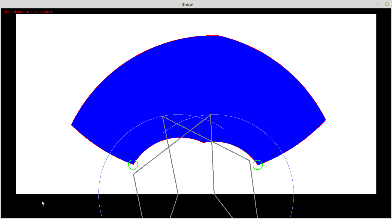
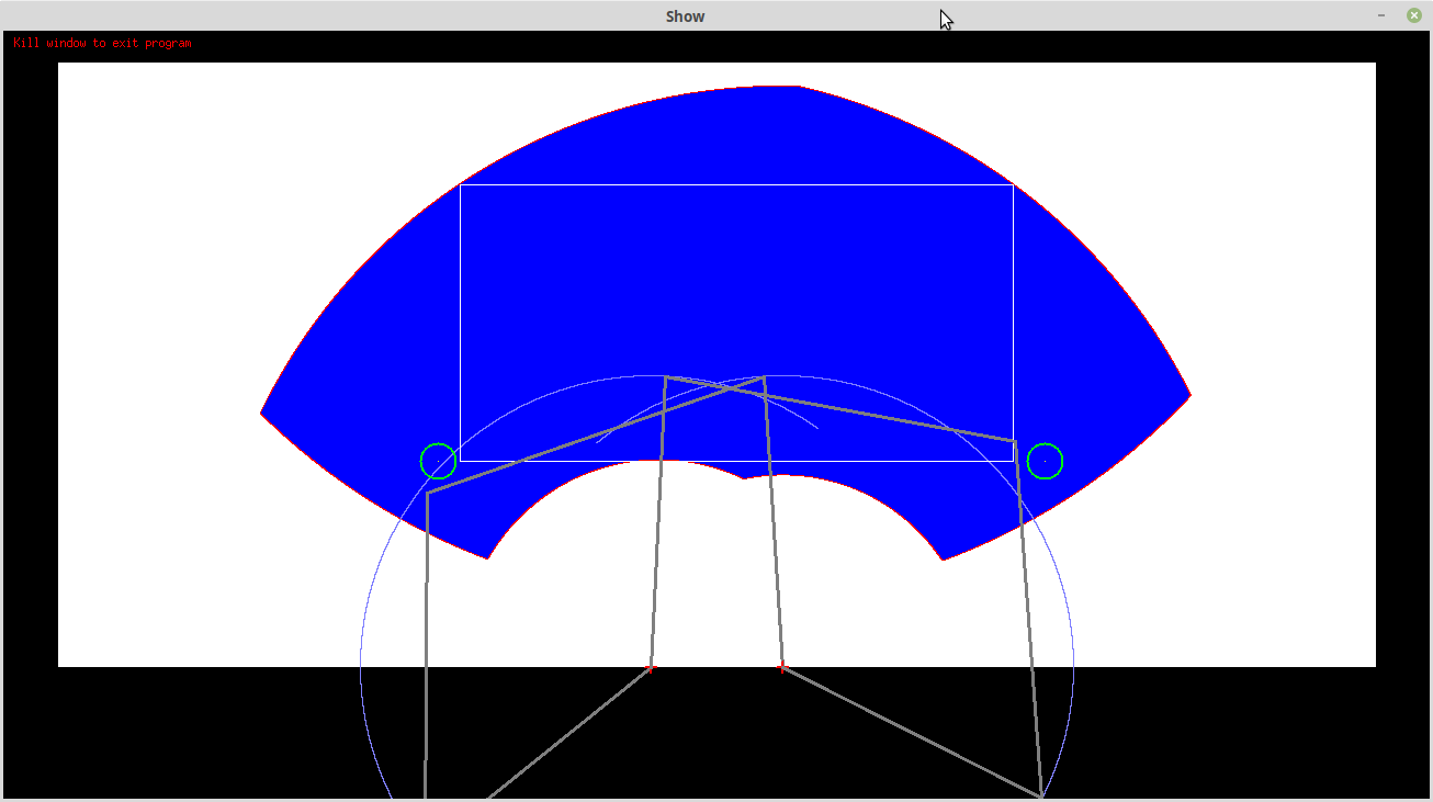
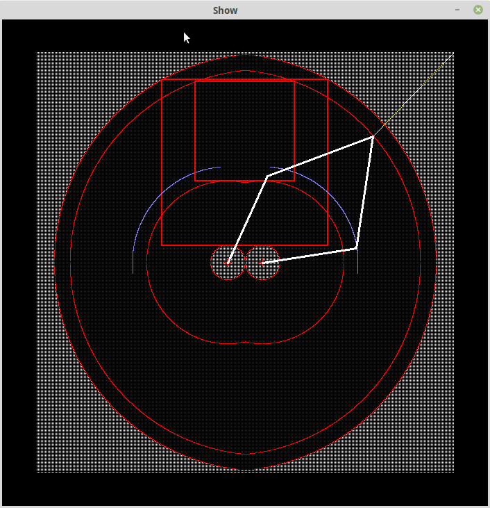
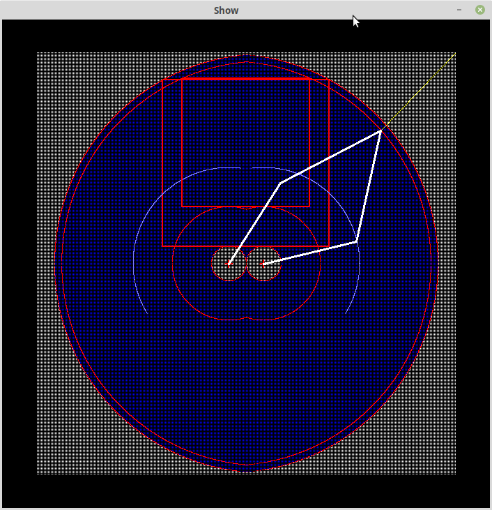
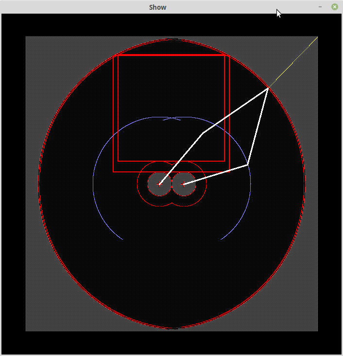
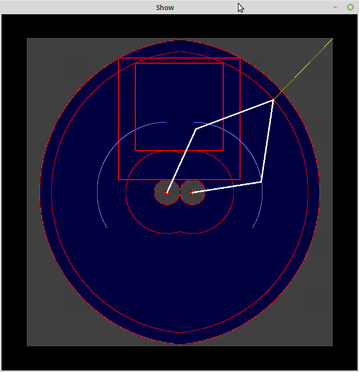
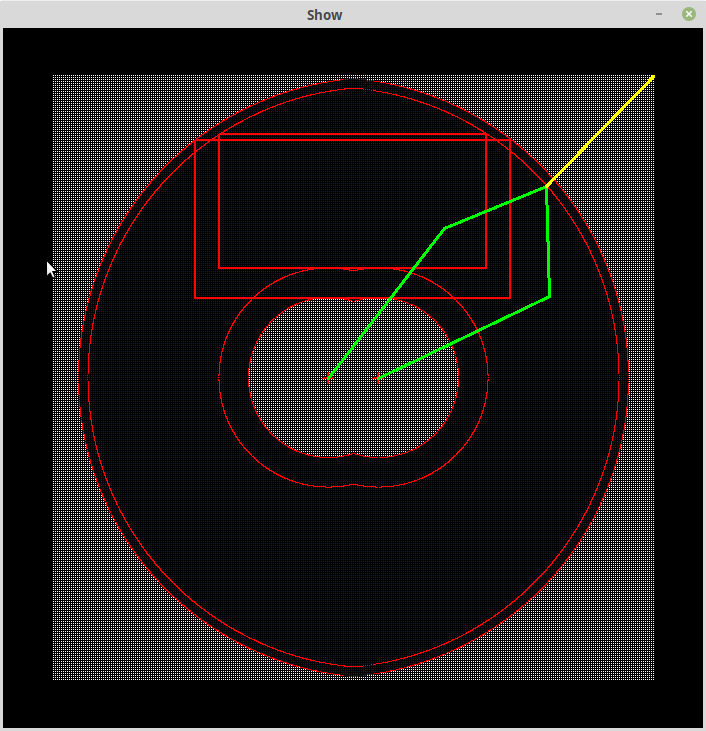
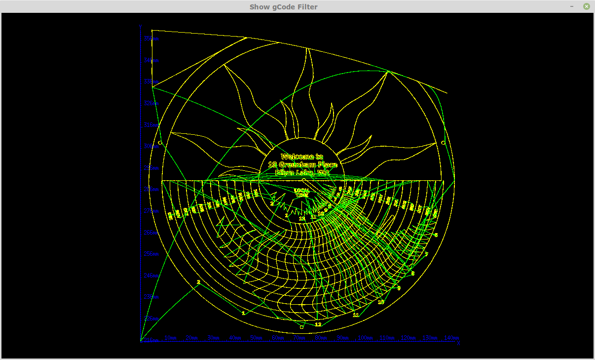
And an example of the work (1/8 micro-stepping):
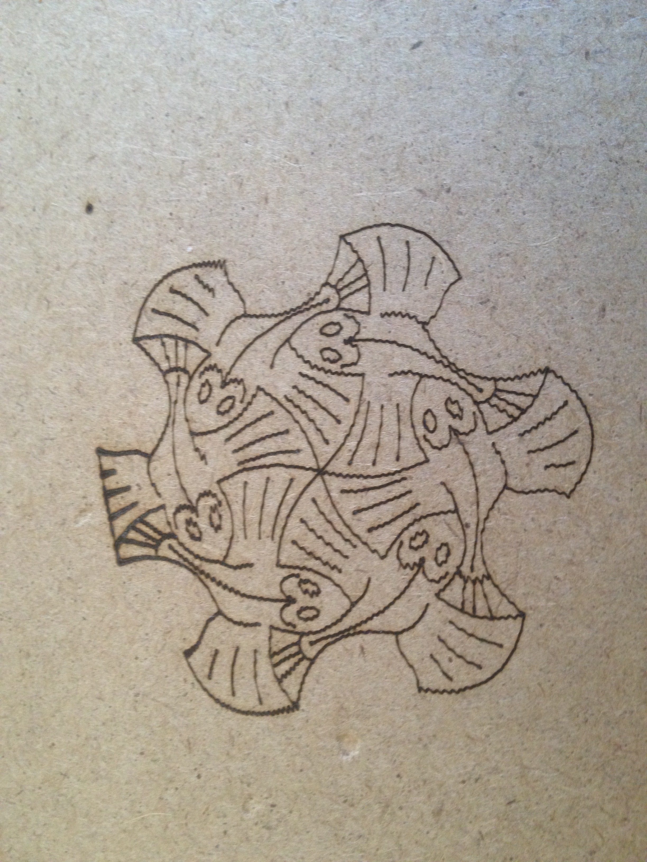
Note the "clipping" on the left of the image, this was deliberate to test the clipping routine.
Also the wavy lines are mix of stepper resolution and arm oscillation. Mostly arm oscillation because they die down towards the end of the "stroke".
The Second SCARA Prototye
The second prototype will be bigger (arms 200 mm and 150 mm) and geared (more torque and higher resolution).
I will be using 2 mm GT2 pulley and belts. I initially started with T5 pulleys and belts but they have too much backlash.
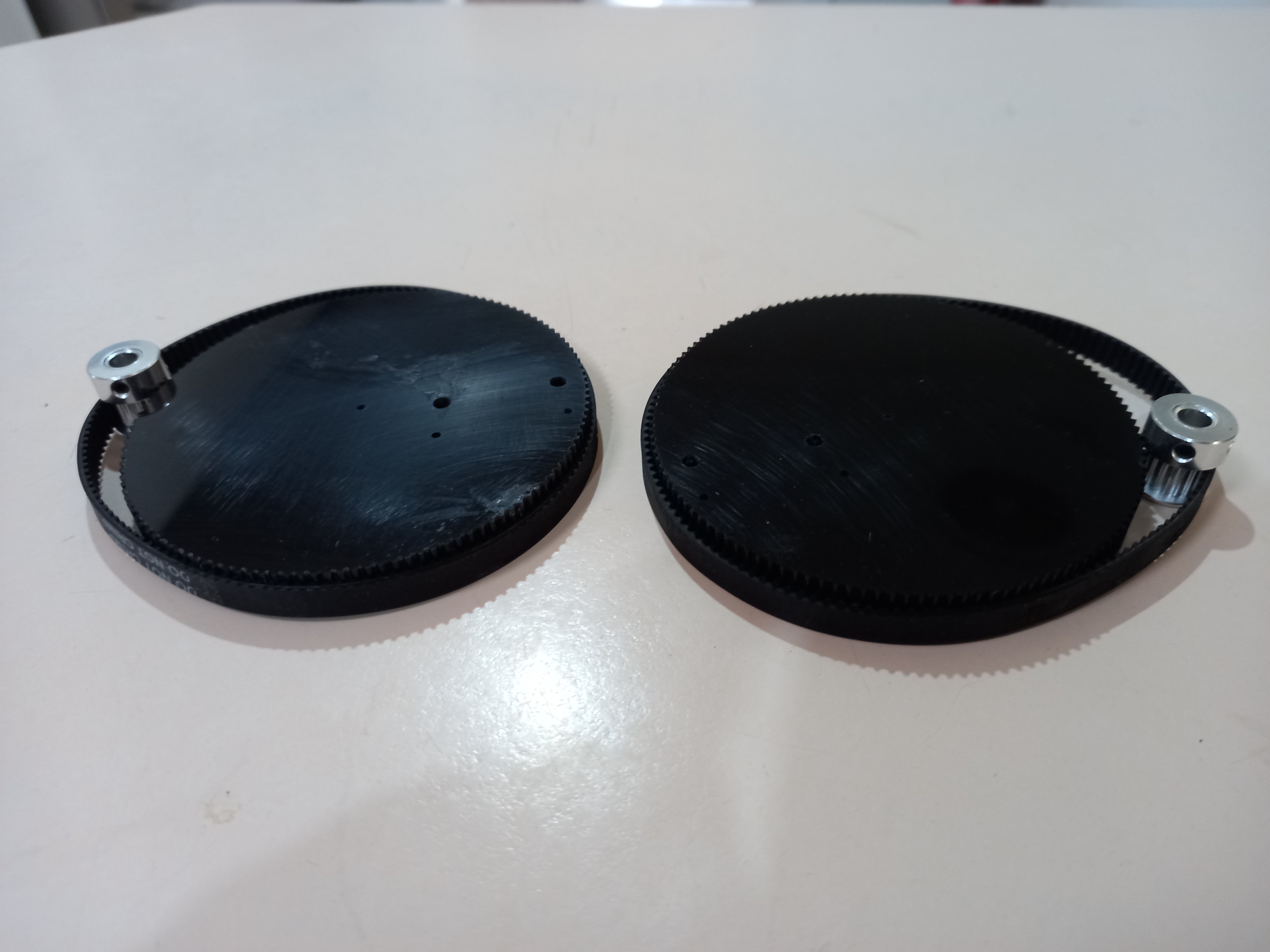
The key design problem for the SCARA is the elbow. With the prototype I relied the stepper motor for the elbow axle. For the geared version, I have designed an integrated pulley and slew ring (https://hackaday.io/project/165560-a-25d-slew-ring):
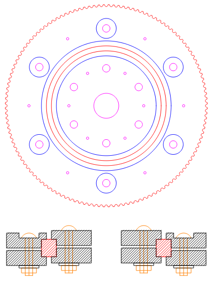
The slew ring uses a 6808 roller bearing. This bearing is 52 mm outside diameter, 40 mm inside diameter and 7 mm thick.
The SCARA Design
I have iterated through many SCARA designs.
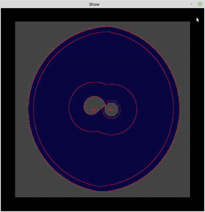
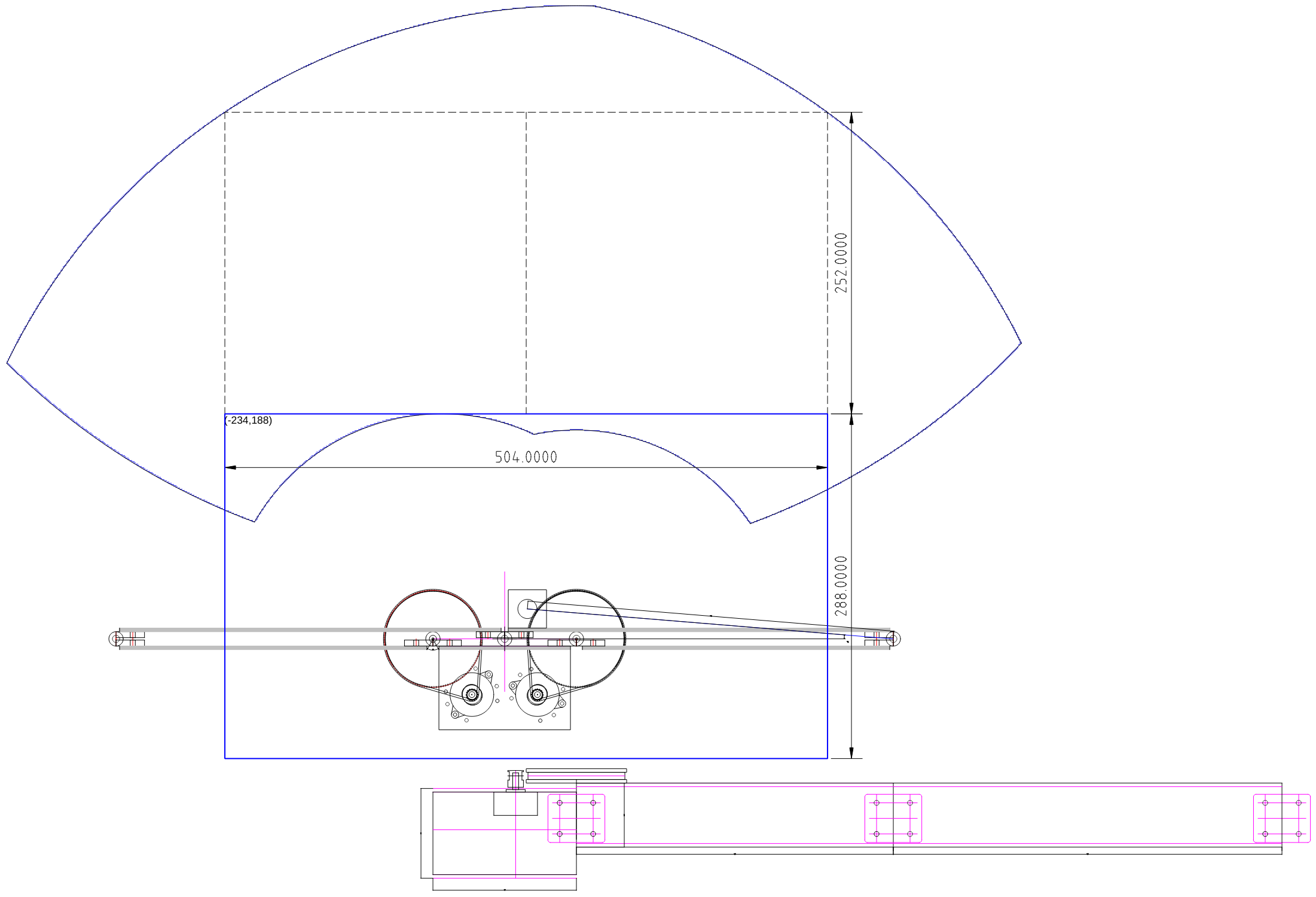
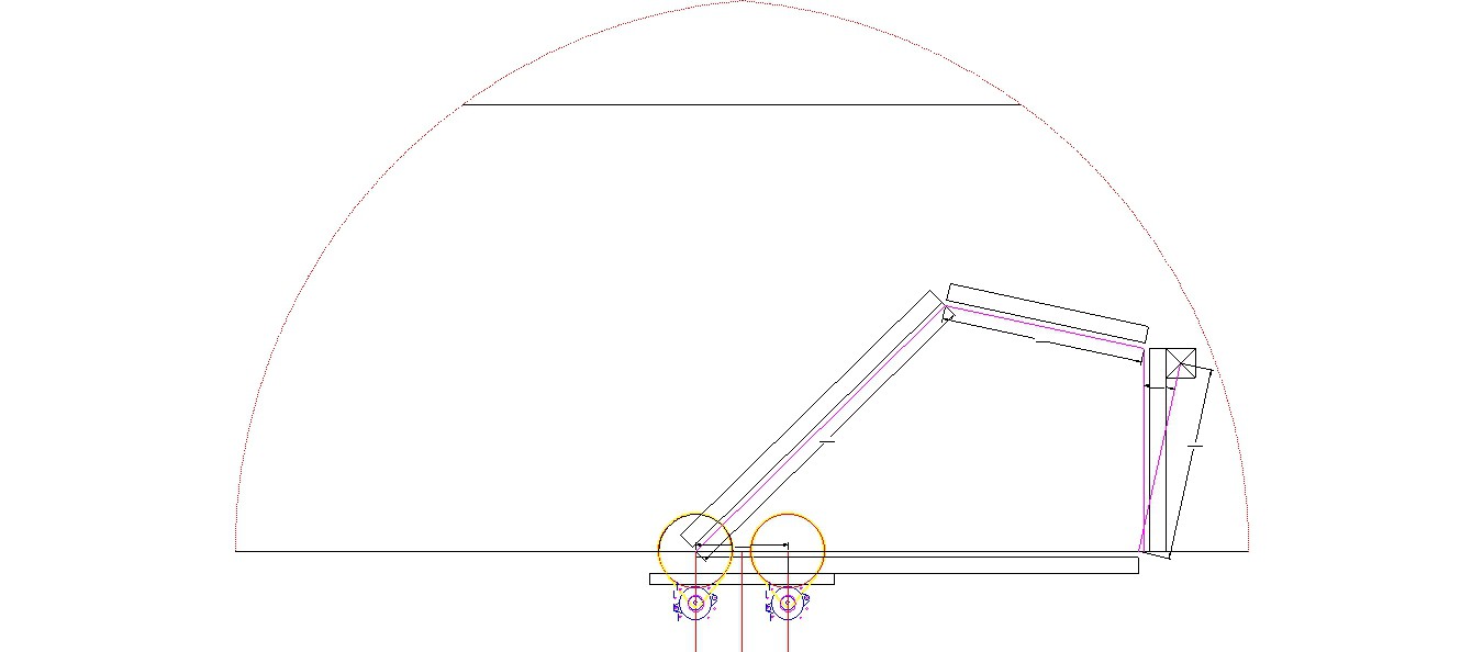
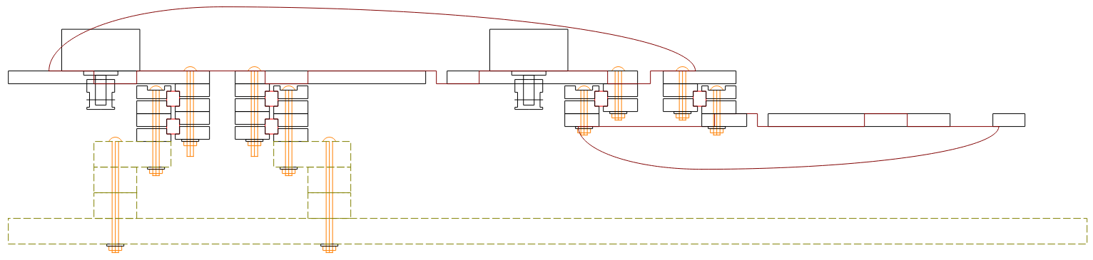
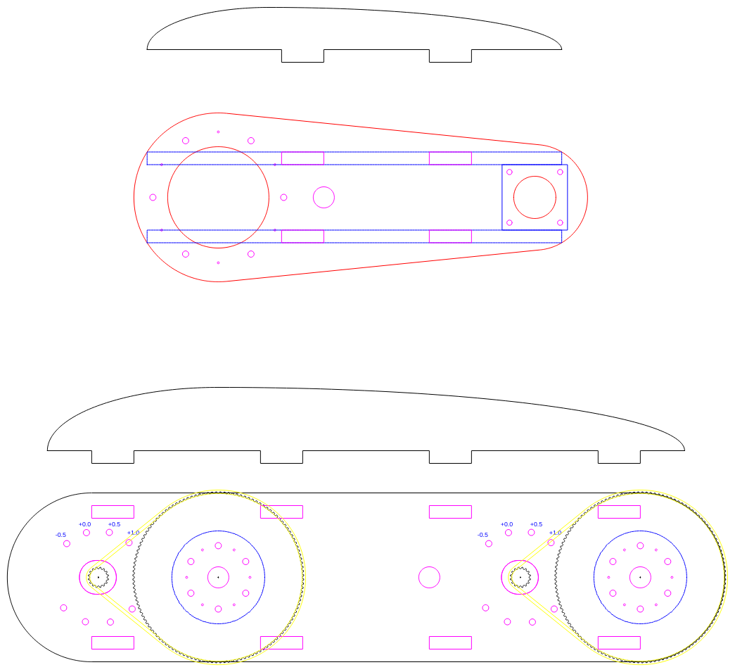
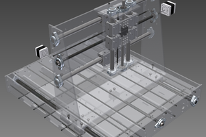
Here a section of the current version for this project:
- The base board and the first three layers are 12 mm MDF.
The following layers are likely to be 6 mm acrylic:
- A double slew ring.
- The the first arm (200 mm between centres). The arm has been stiffened with a vertical element (making a "T" section).
- The single slew ring attaches the second arm (150 mm between centres).
- A laser engraver will be attached to the end of the second arm.
- The second arm is also stiffened with two vertical elements (making a "U" section).
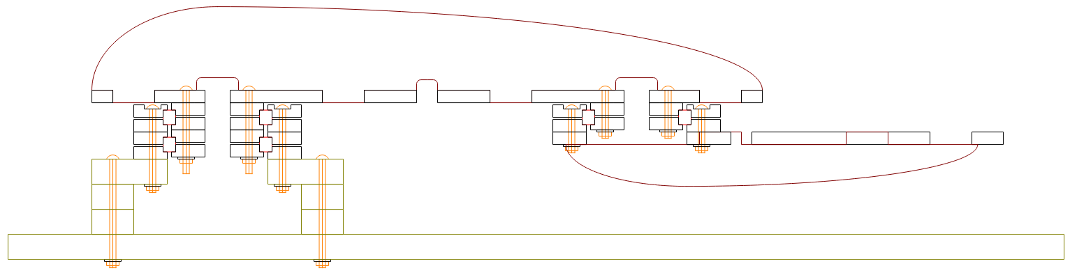
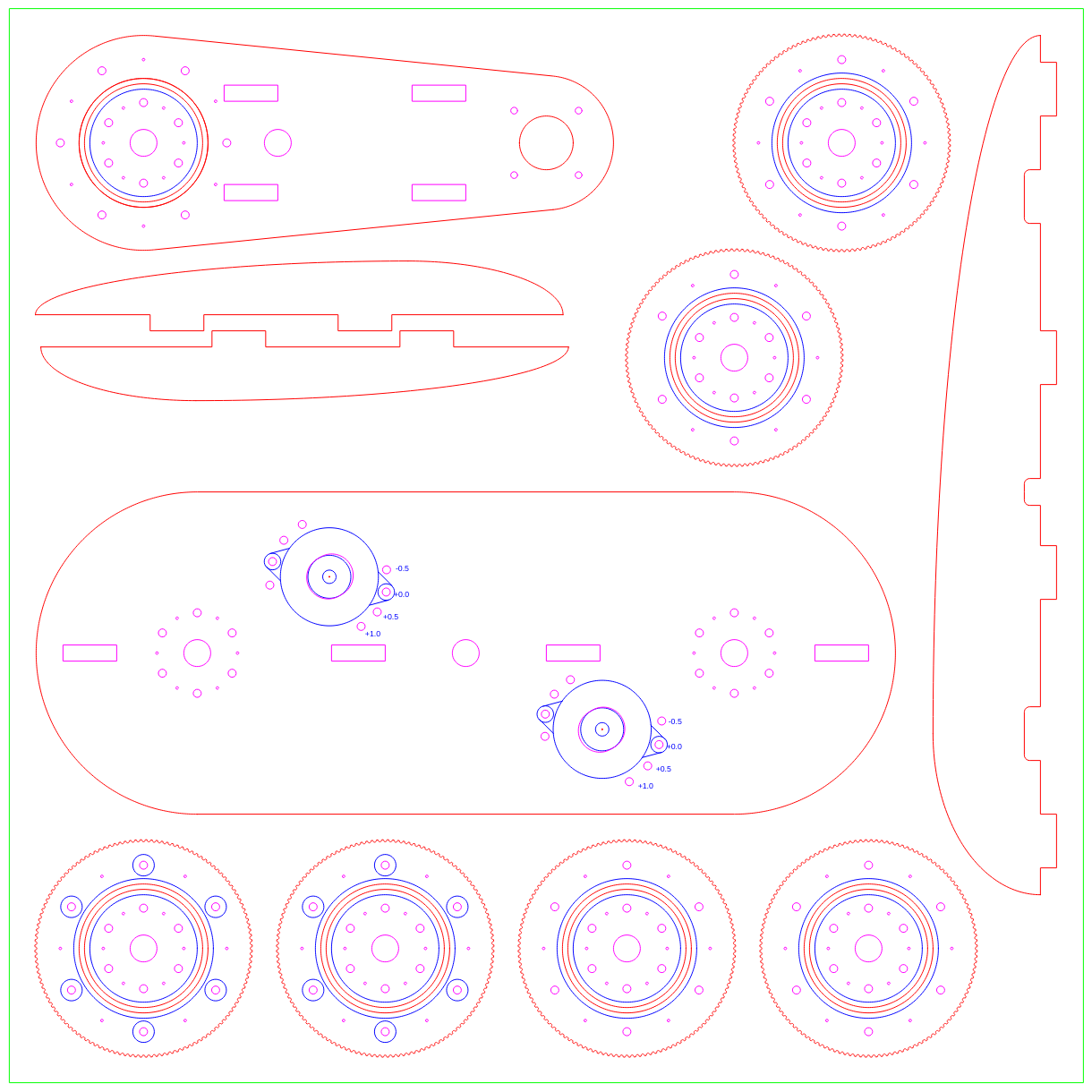
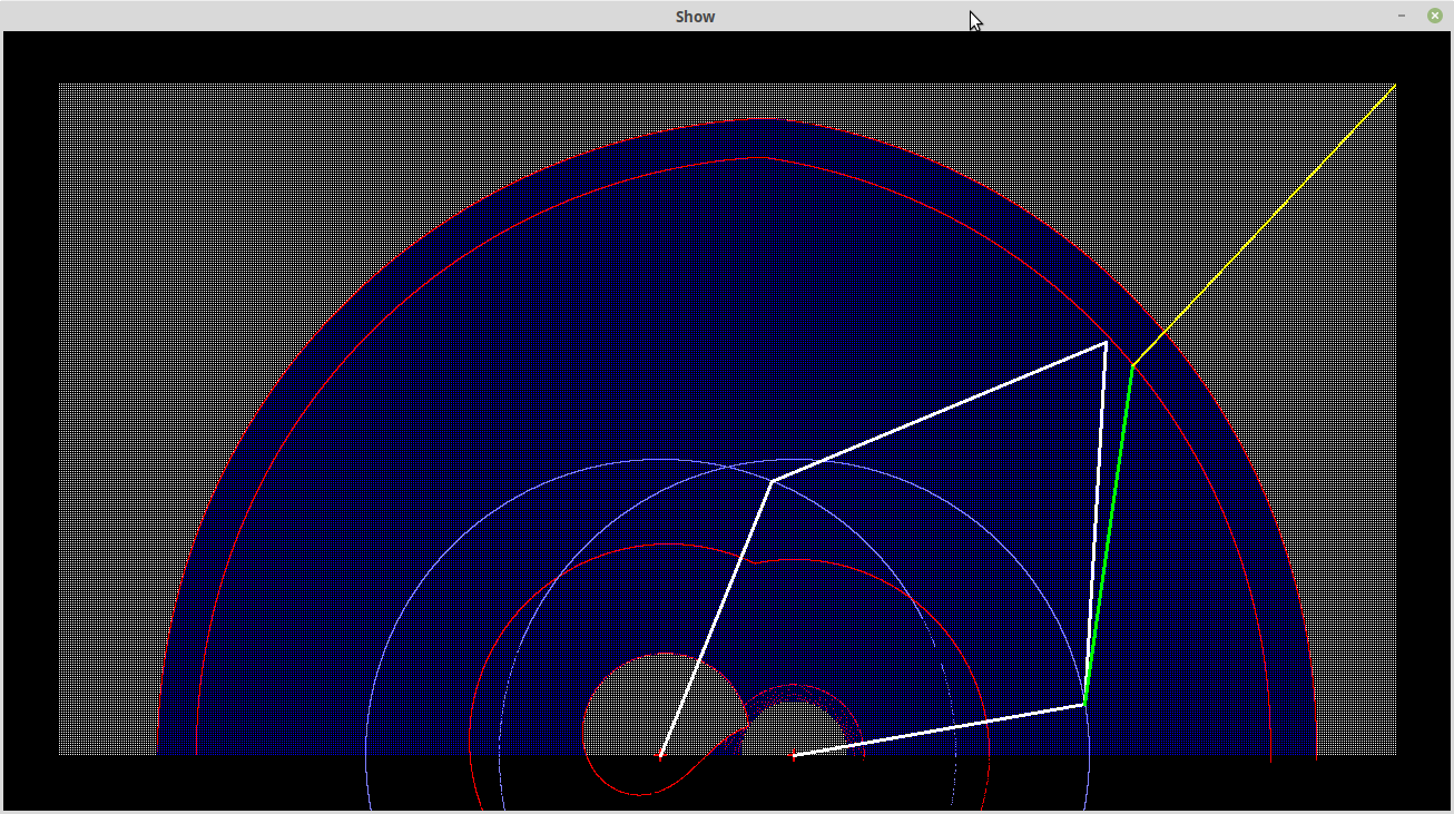
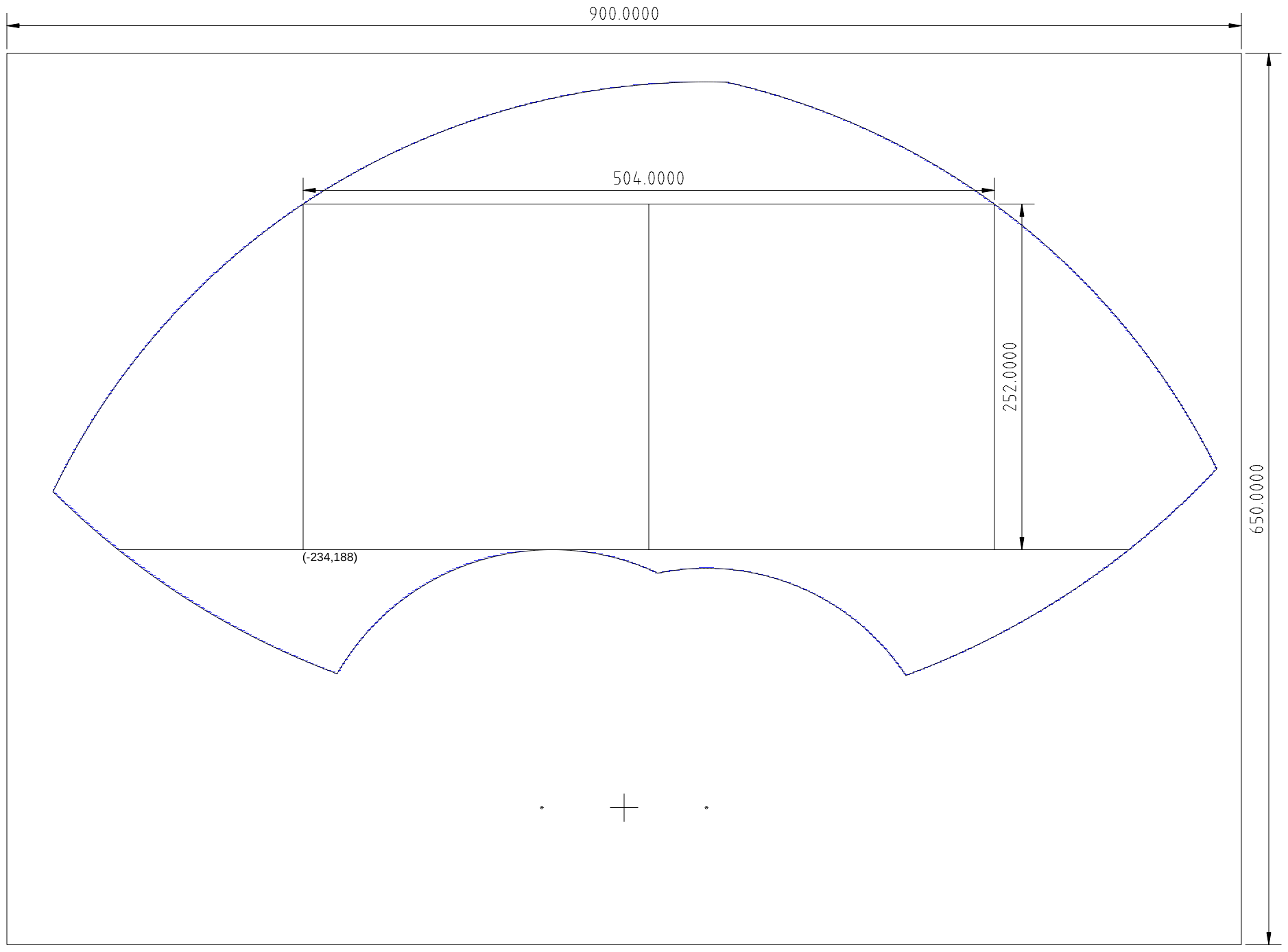
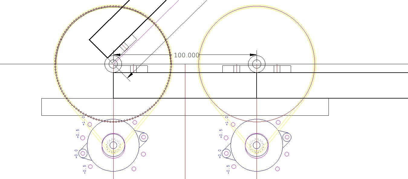
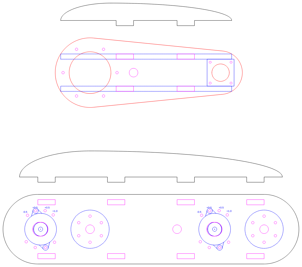
Here are some plans:
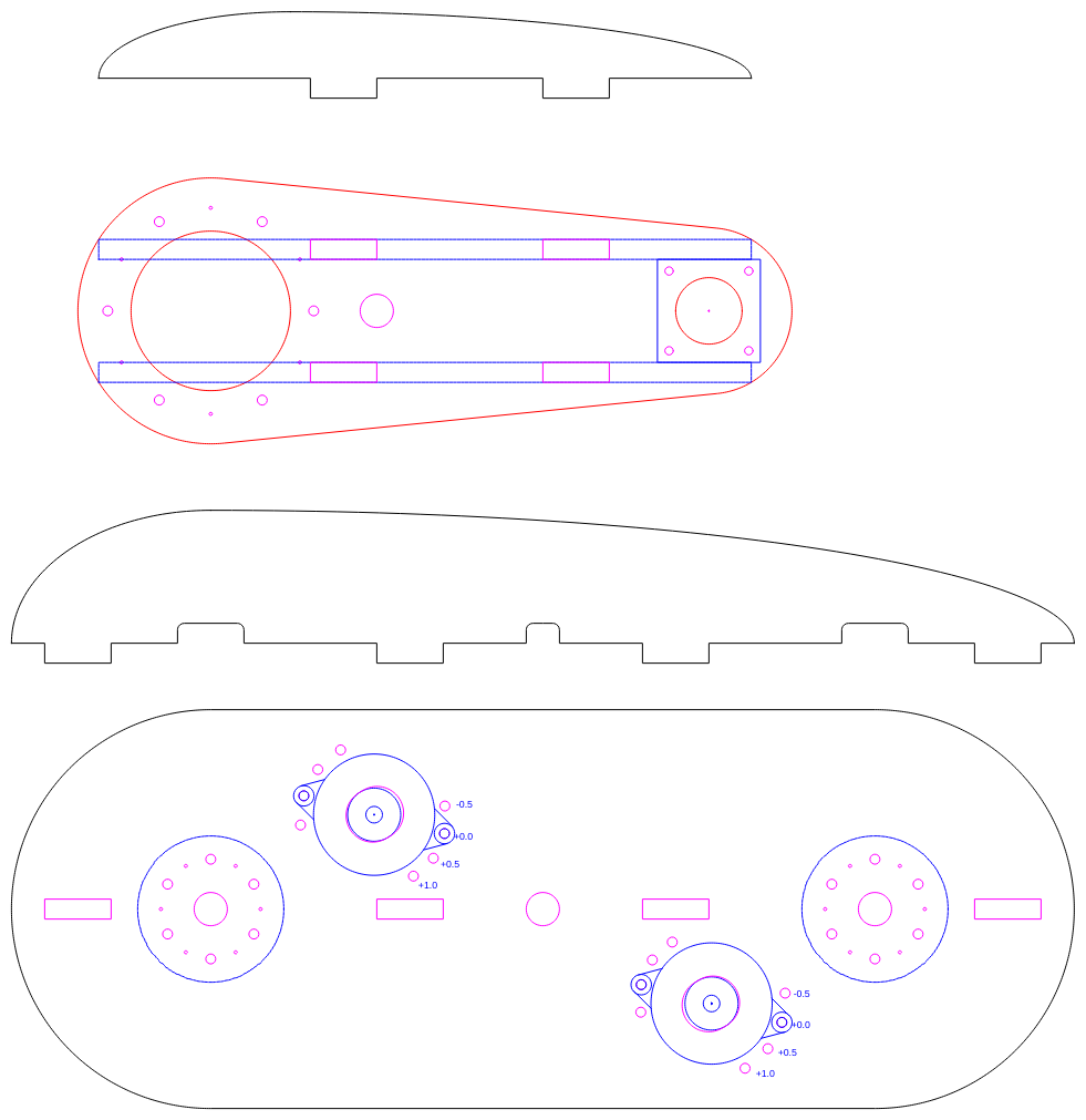
The first arm (bottom of image) shows the stepper motor mounts and the belt tension adjustment system. The stiffening elements are slot and tab design, and will glued.
I am contemplating a "U" section design for the first arm. The rearrangement may result in a smaller arm with better balance.
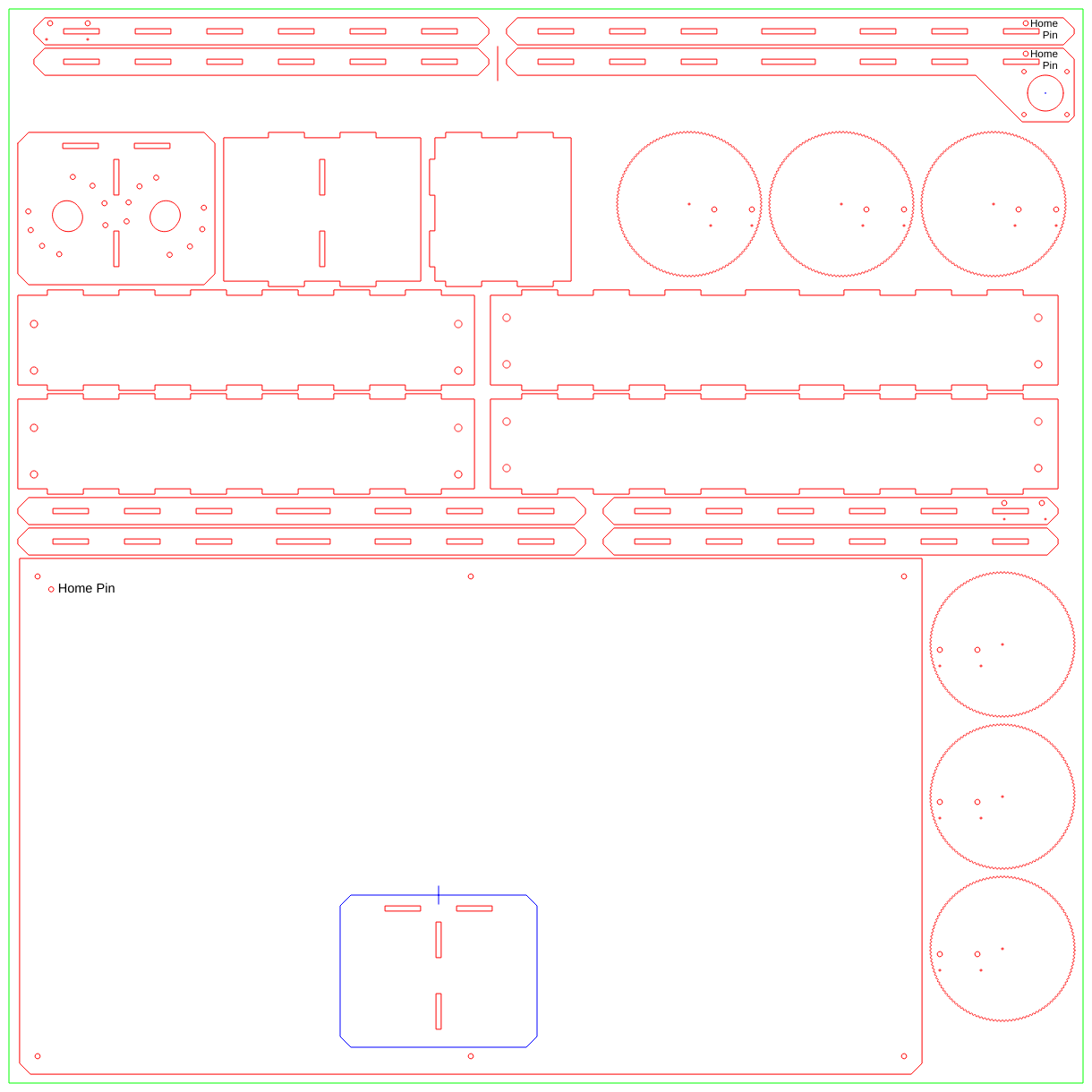
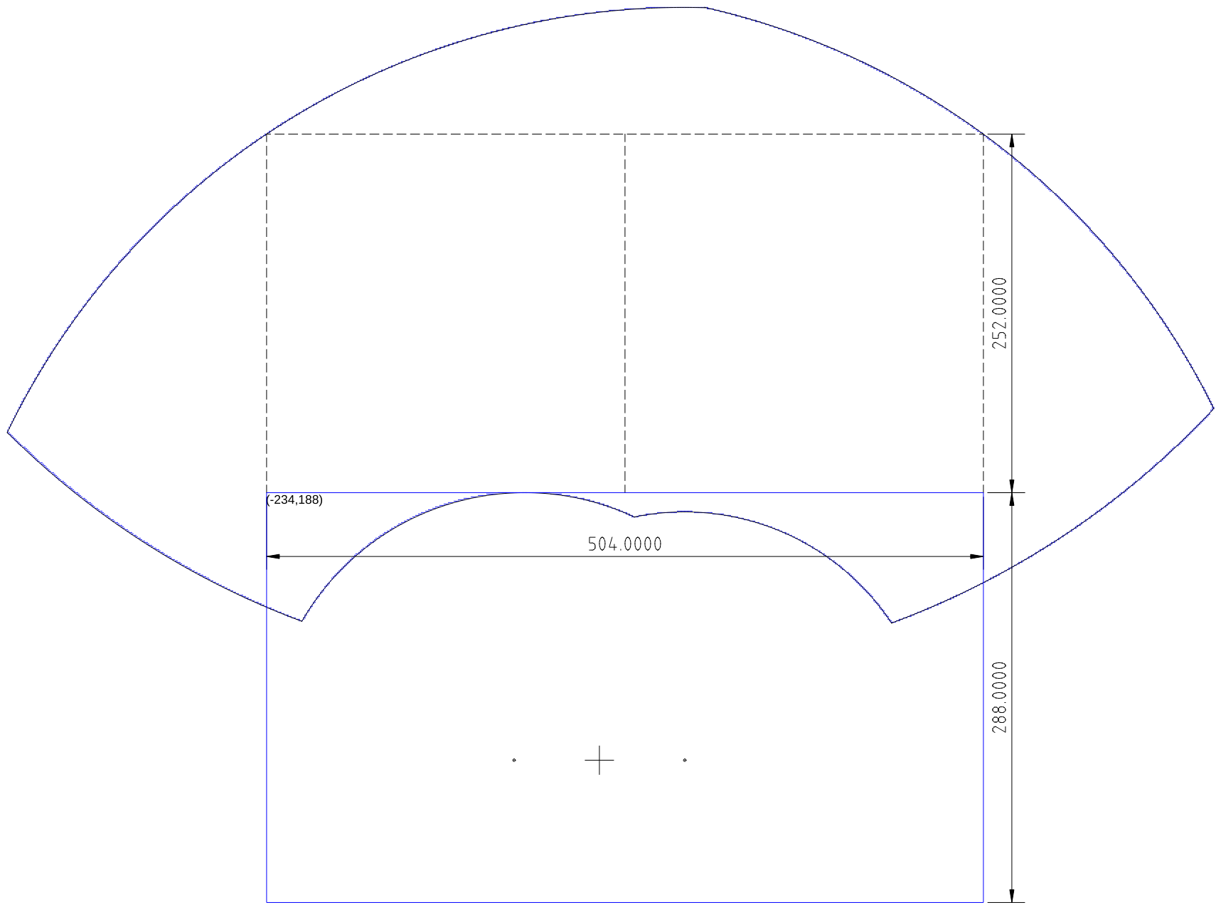
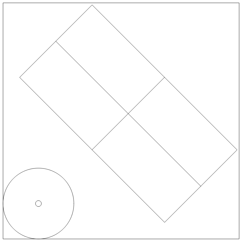
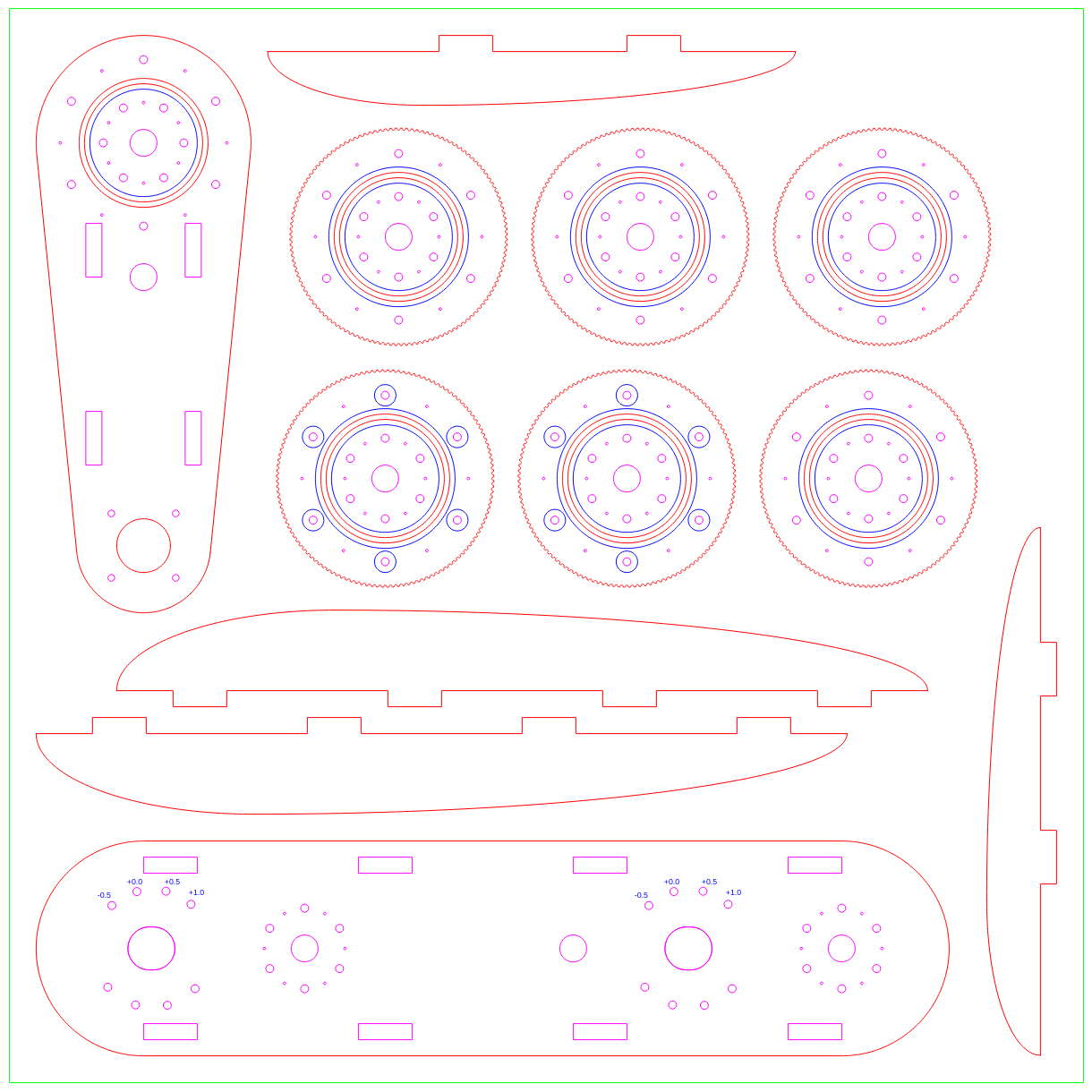
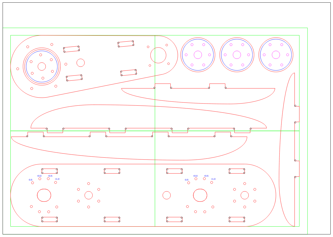
Laser Cutter Layout
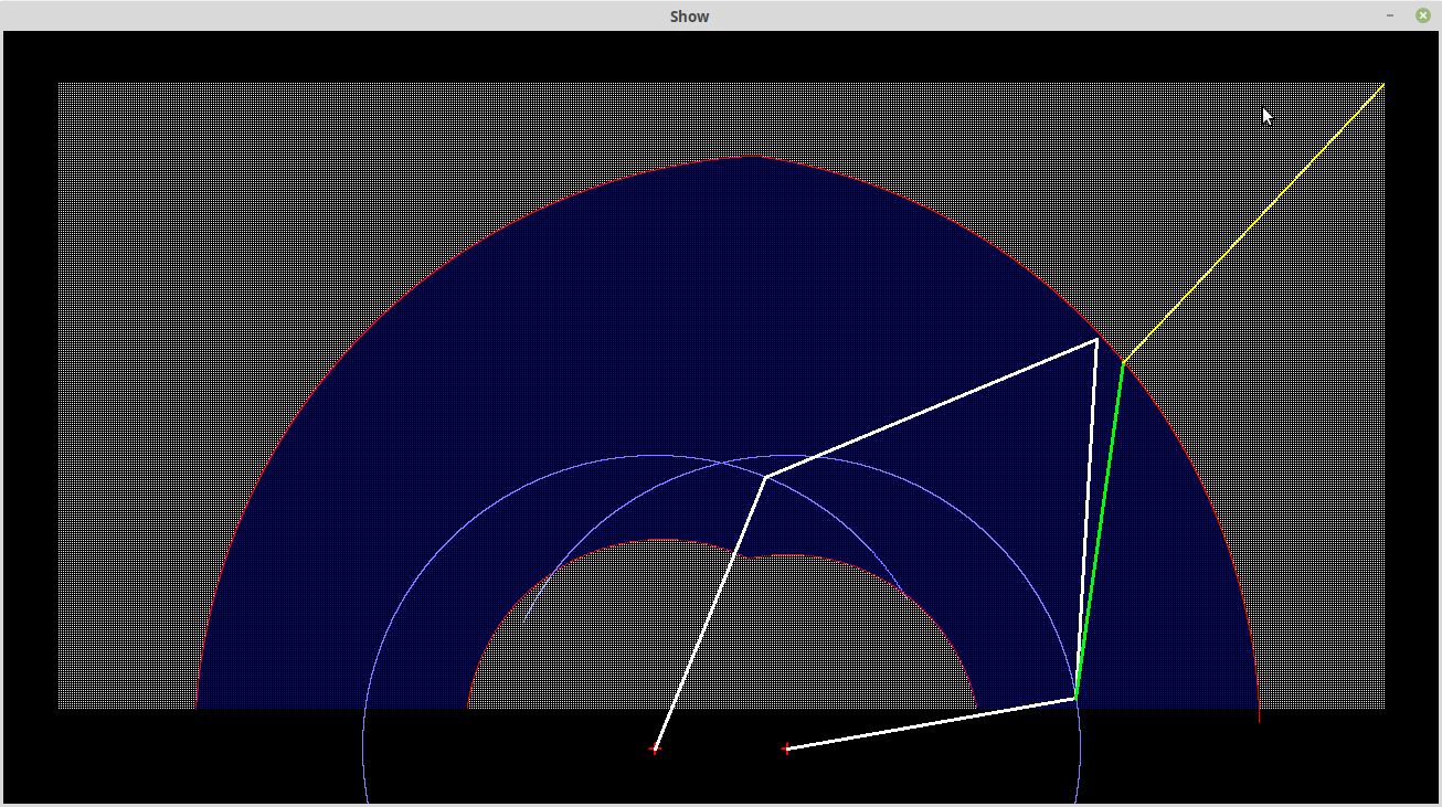
I have laid out the design for a laser cutter. The bearing pockets can be cut later with my 2.5D CNC machine:
The design is not quite ready, however for the laser cutter. I still have to design the base board.
AlanX


 Kert
Kert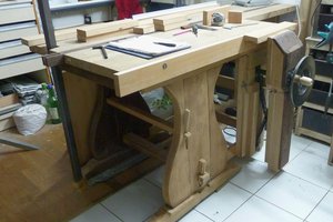
 [zit] Olivier Gade