Inspiration
When I was in grade 9 I watched Ben Eater create a computer from logic chips and my mind exploded. I realized computer architecture was just like LEGOs and that is how I spent my entire high school life doing. I wanted to create a computer better than Ben Eaters. His was an 8-bit computer was 16 bytes of RAM and 16 instructions. I needed to do something far better. So I began to design my first computer in grade 9 to grade 10 summer. This project is about my most recent creation. It is a 16 bit machine with many useful instructions. It is similar to Ben Eaters computer except that:
- Instructions can have up to 16 micro states
- If an instruction does not need 16 micro states to execute, the micro state counter is reset
- Stack Pointer hardware
- LCD display compatible
- 32 KiloByte RAM, 4 KiloByte ROM, 256 Byte Stack RAM
- Max. 128 instructions
- Conditional branching
- I/O ports
Understanding the Architecture in Words
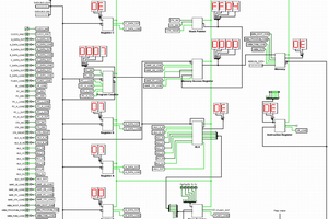
Print the Instruction Set and the Block Diagram of the architecture, then read this and use that for reference.
This architecture is linear. Once an instruction is finished the current address in the program counter is used as the location of the next instruction to execute. Some instructions manipulate the program counter themselves usually by the increment of the program counter or loading the program counter during jump instructions. There is no parallel computing or memory management but that is an area I would like to explore in the future.
A program is just a list of instructions that the computer follows exactly in the order you list them in. It has memory where you place the instruction and variables in. This computer has a RAM memory of 32768 Bytes and ROM memory of 4096 bytes. Something different about this computer is that instruction codes are made of sometimes 1 or 3 bytes but for the most part, most instructions need 2 bytes. The first byte is always an instruction. The address larger than the first byte stores the operand and the number of operands is dependent on the micro code of the computer which is explained later or can be found in the pictures section(entire assembly language I made).
The computer distinguishes between RAM and ROM memory through logic gates explained in the memory section. When the computer is fully reset it will think that the first instruction is stored at memory address 0. If we have a program already stored starting from address 0, it will begin to execute.
To understand how a computer like this executes we must look at something called the instruction cycle. The instruction cycle consists of 3 main steps. There is a state counter (decade counter), counting at a frequency that sets the speed of the CPU. It resets when it reaches 16 or gets a signal saying that an instruction is done executing and does not need the full 16 states to complete. It just keeps track of which instruction state is active. State 1 on the counter represents fetch, state 2 represents decode, and 3 -16 all represent execution states. Execution states vary depending on state 1 and 2). The Control ROM takes input from the state counter and instruction register and outputs 32 control signals intended for all the components 1 step function that are hardwired in logic.
Instruction Cycle
Fetch
The state counter is at state 1, which signifies to the control ROM that it is the fetch state. When the control ROM sees that the computer is in its fetch state it will do the following no matter what.
The contents of the Program Counter are read by the MAR.
*Clock step*
Decode
The state counter is now at state 2, which signifies to the control ROM that it is the decode state. When the control ROM sees that the computer is in its decode state it will do the following no matter what:
The contents of RAM that are stored into the address of the MAR are read by the...
Read more » ammarbhayat28

 Ruud van Falier

 Pavel
Pavel
 spudfishScott
I have to tip my hat to you for staying sane with all those breadboards and wires. I see you even glued some of them down.