 Daren Schwenke
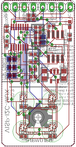
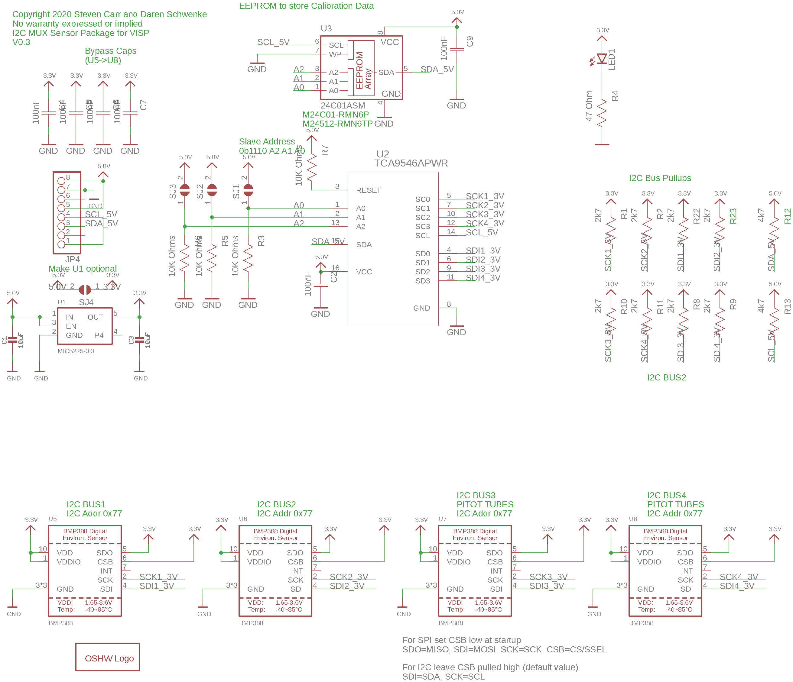
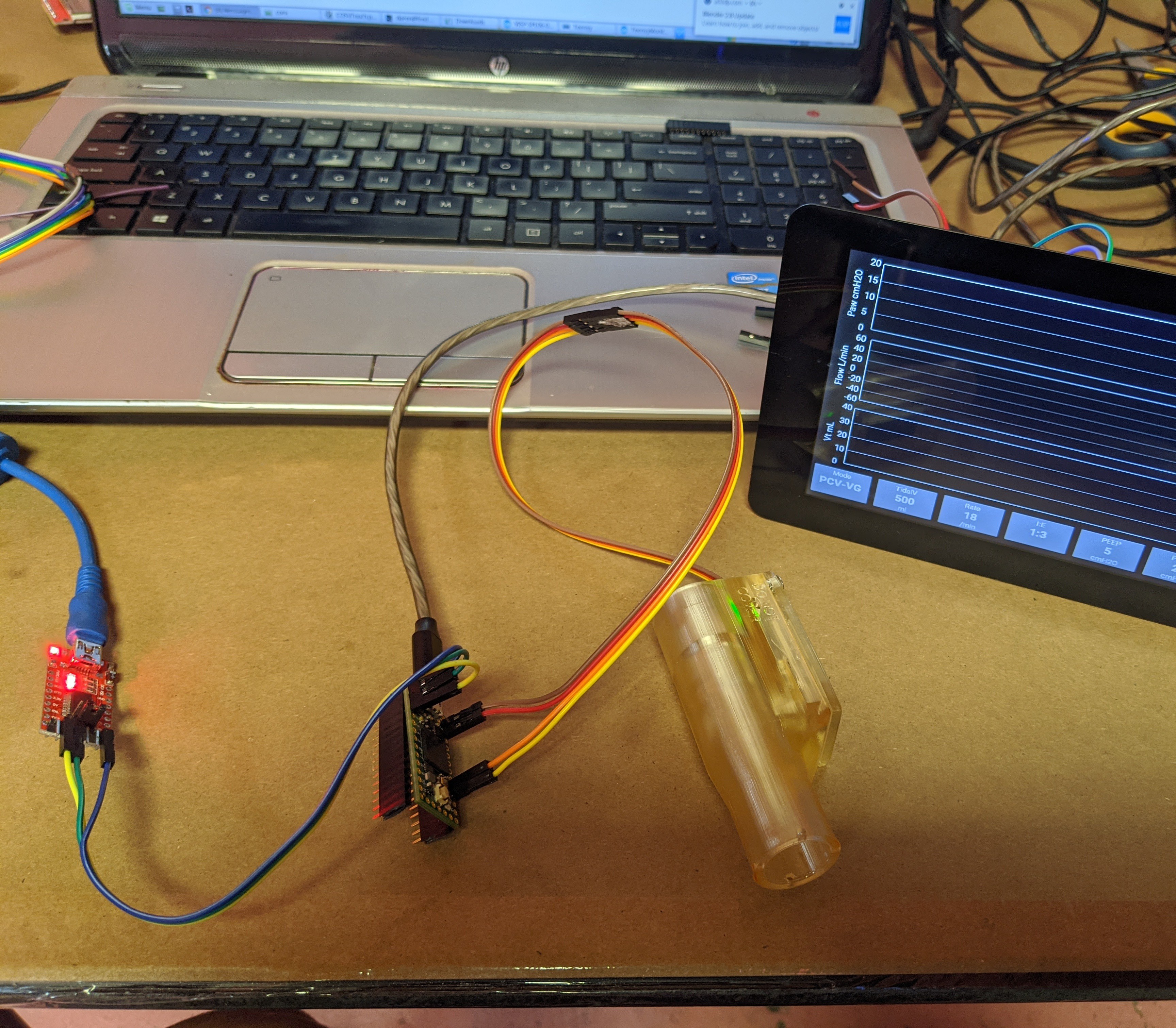
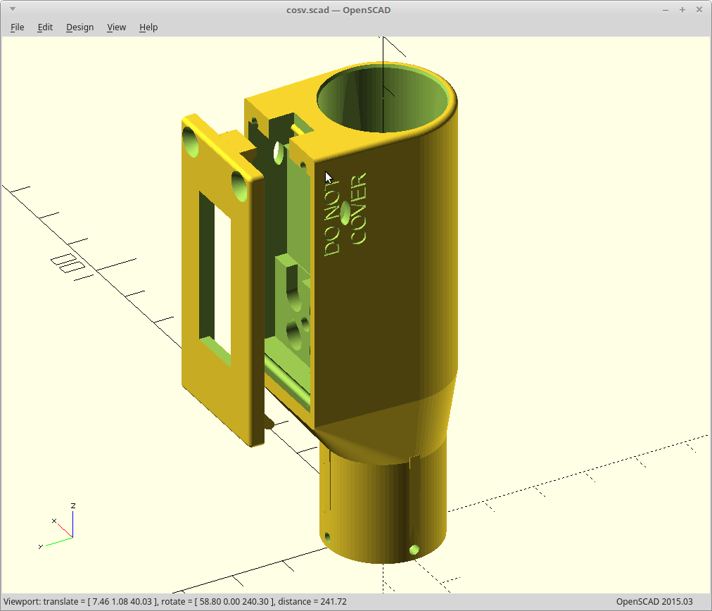
@Steven.Carr has designed new BMP388 boards to be our last generation and official board for the VISP. Boards are currently out for quote with ScreamingCircuits.com for fabrication and assembly.
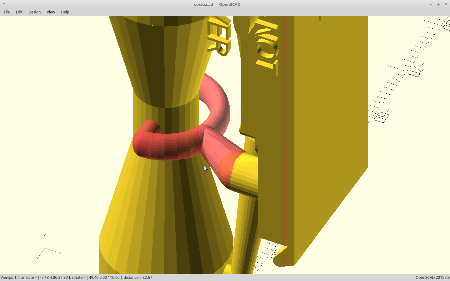
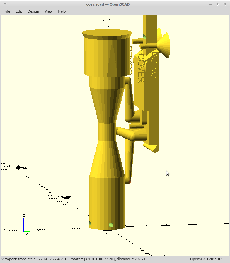
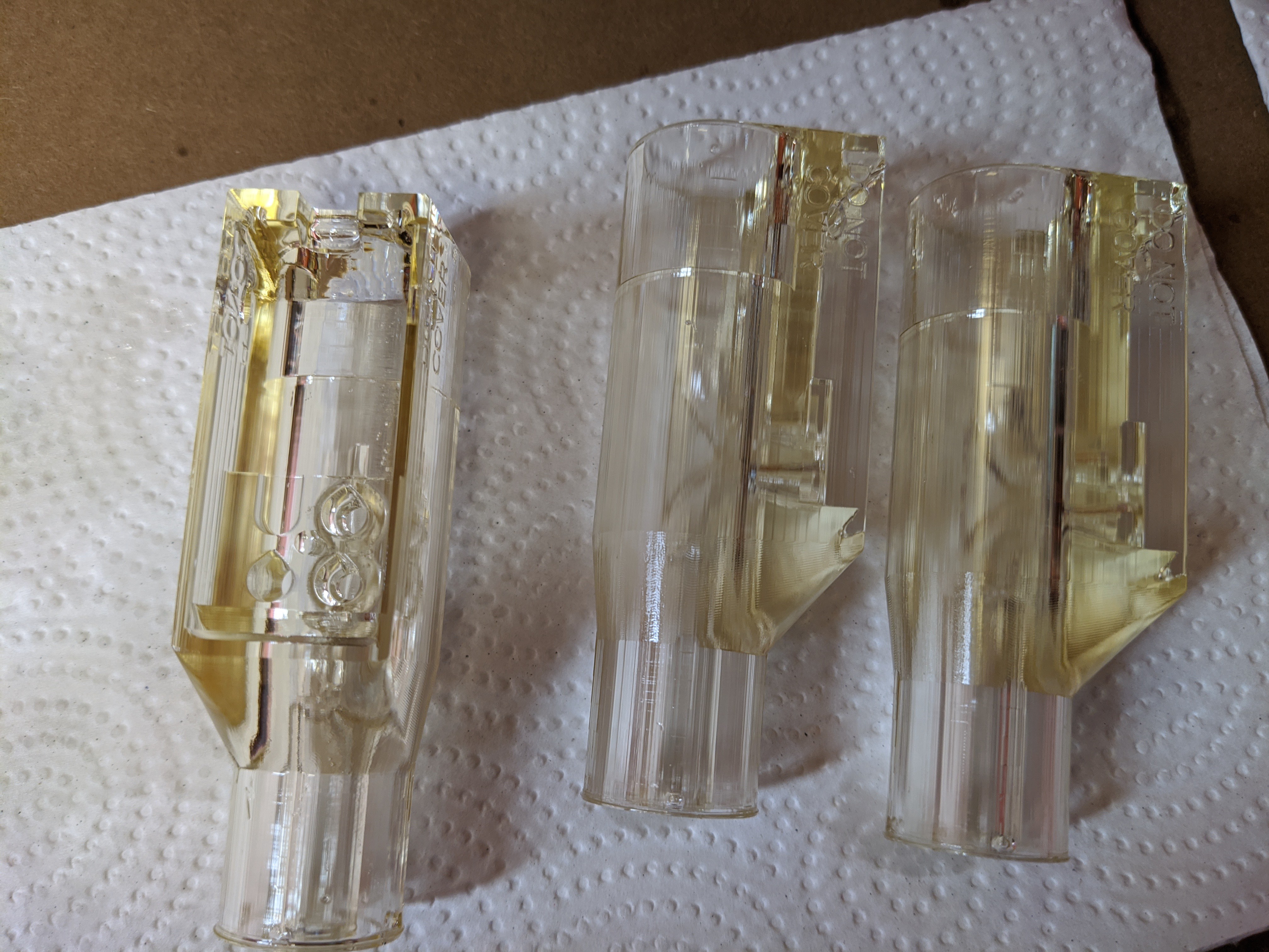
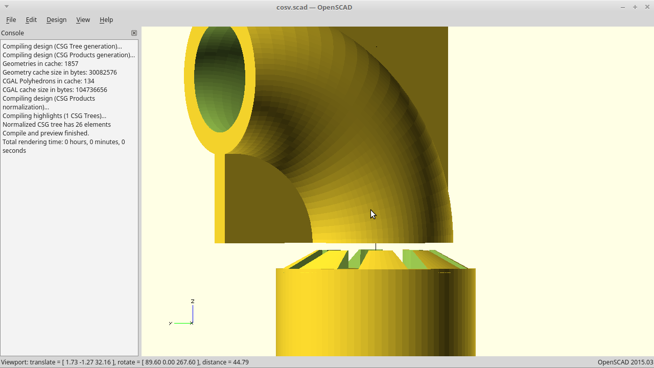
The 3D model matches the boards and the prints are pretty consistent. The overhang for the board area for FFF may need to be a little more gentle: at normal speeds it can get messy. Looks great using SLA.
For FFF, this was rendered out to use a 0.4mm nozzle, 0 walls, all infill, concentric. This results in a better print as then the printer only leaves the solid area once per layer to jump to the middle 'break off' support for the lower pitot tube. When I say rendered out for a 0.4mm nozzle, I mean that critical wall thicknesses are an exact multiple of the nozzle size. If you want to use a different nozzle, it would be much better to adjust the model and render again to keep this trait.
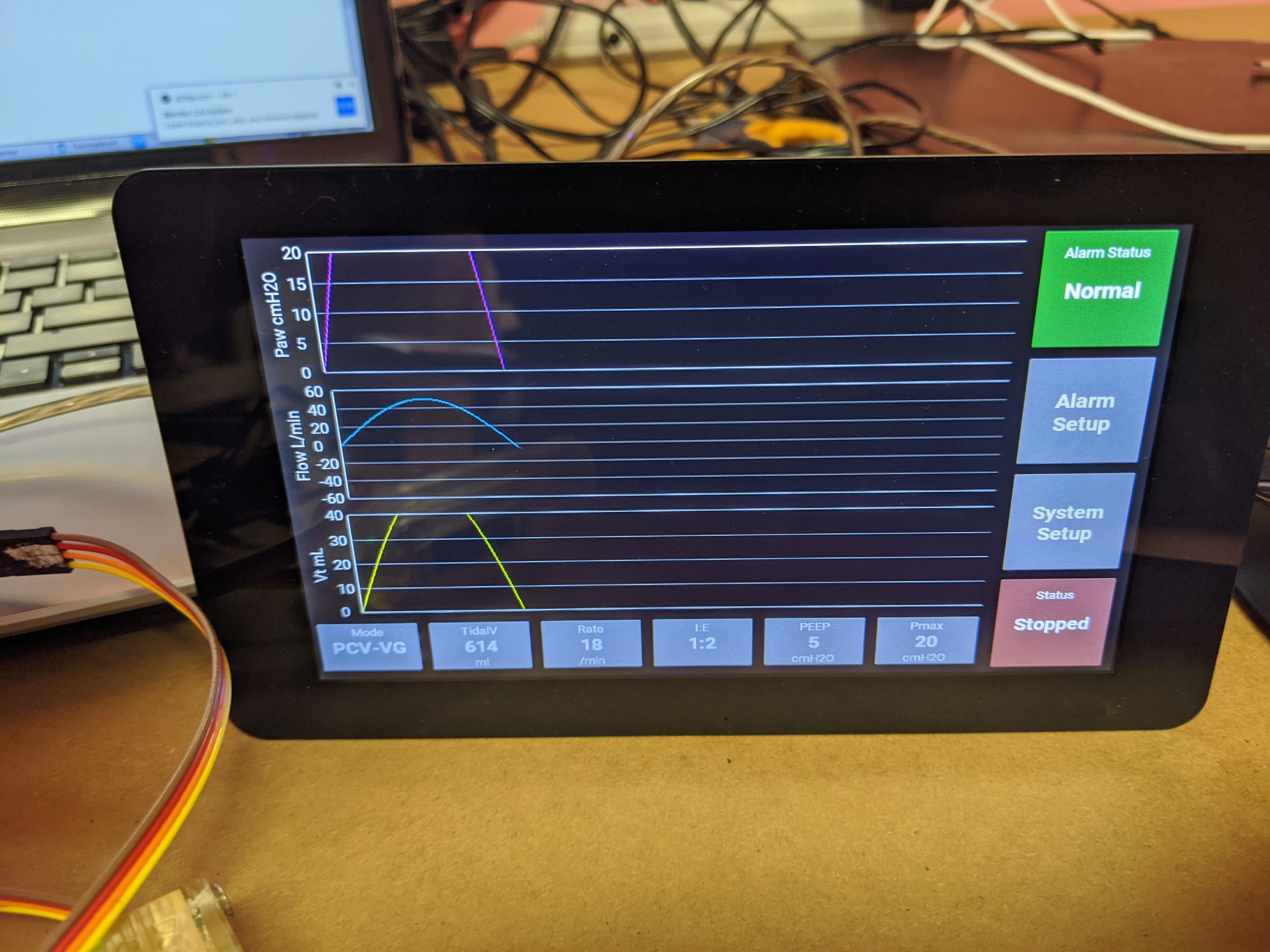
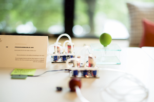
We have moved to a venturi style orifice and have verified the fit of the PCB and piggy back LCD for on mask feedback.
A ventilator sensor shortage is brewing...
Subproject of #COSV - Cam Open Source Ventilator


 CaptMcAllister
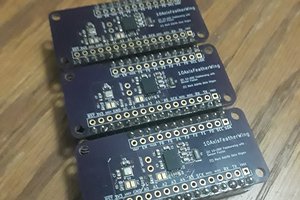
 Amitabh Shrivastava
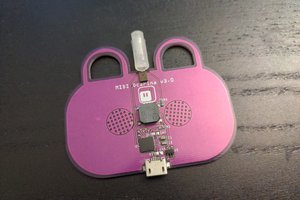
 deʃhipu
If you do a deep dive into the SFM3300, they use a perforated aperature plate. This is a nice setup as it would help to break up vortices (A.K.A Karman Street) which could present a pressure modulation at your sensor ports and possibly a pertubation in your transfer function.