Close
0%
0%

Hi torque 3d printed cheap robot actuator

Cheap 3d printed hi torque robot actuator with electronics

Similar projects worth following
Hi torque 3d printed cheap robot actuator with simple electronics

Goals

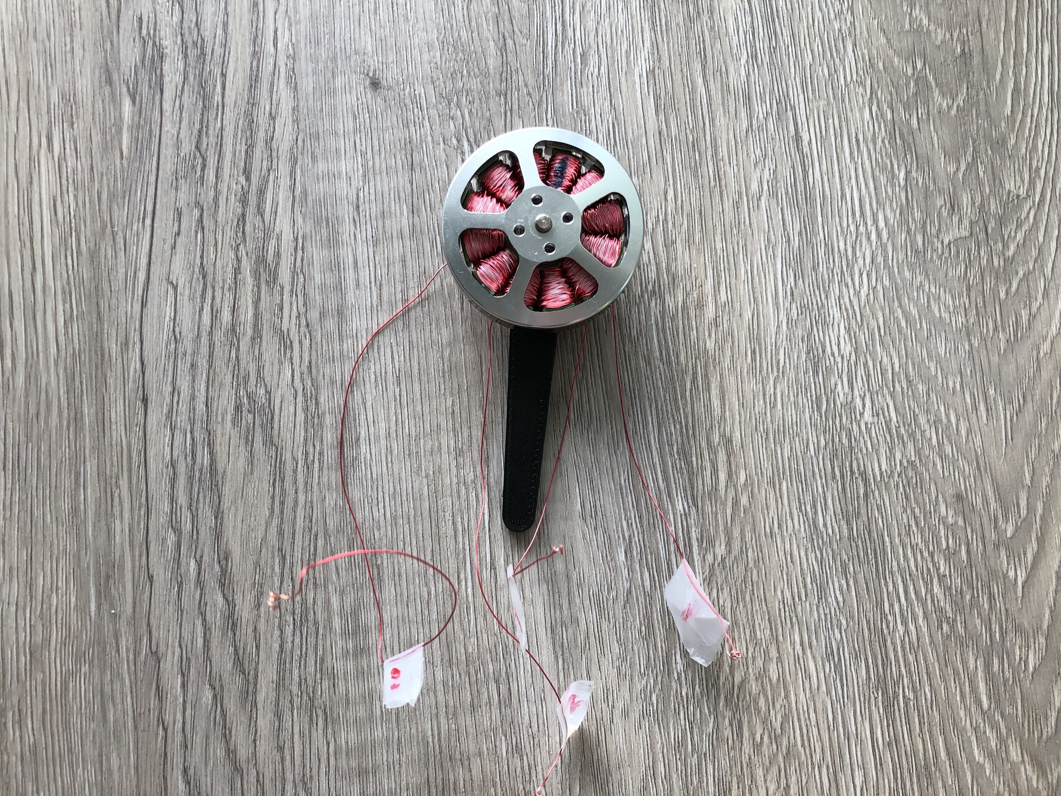
  • 10kg/cm torque at 180 degrees per second (30 RPM)
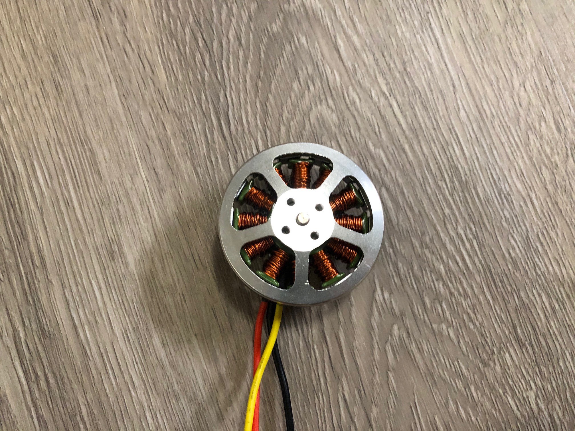
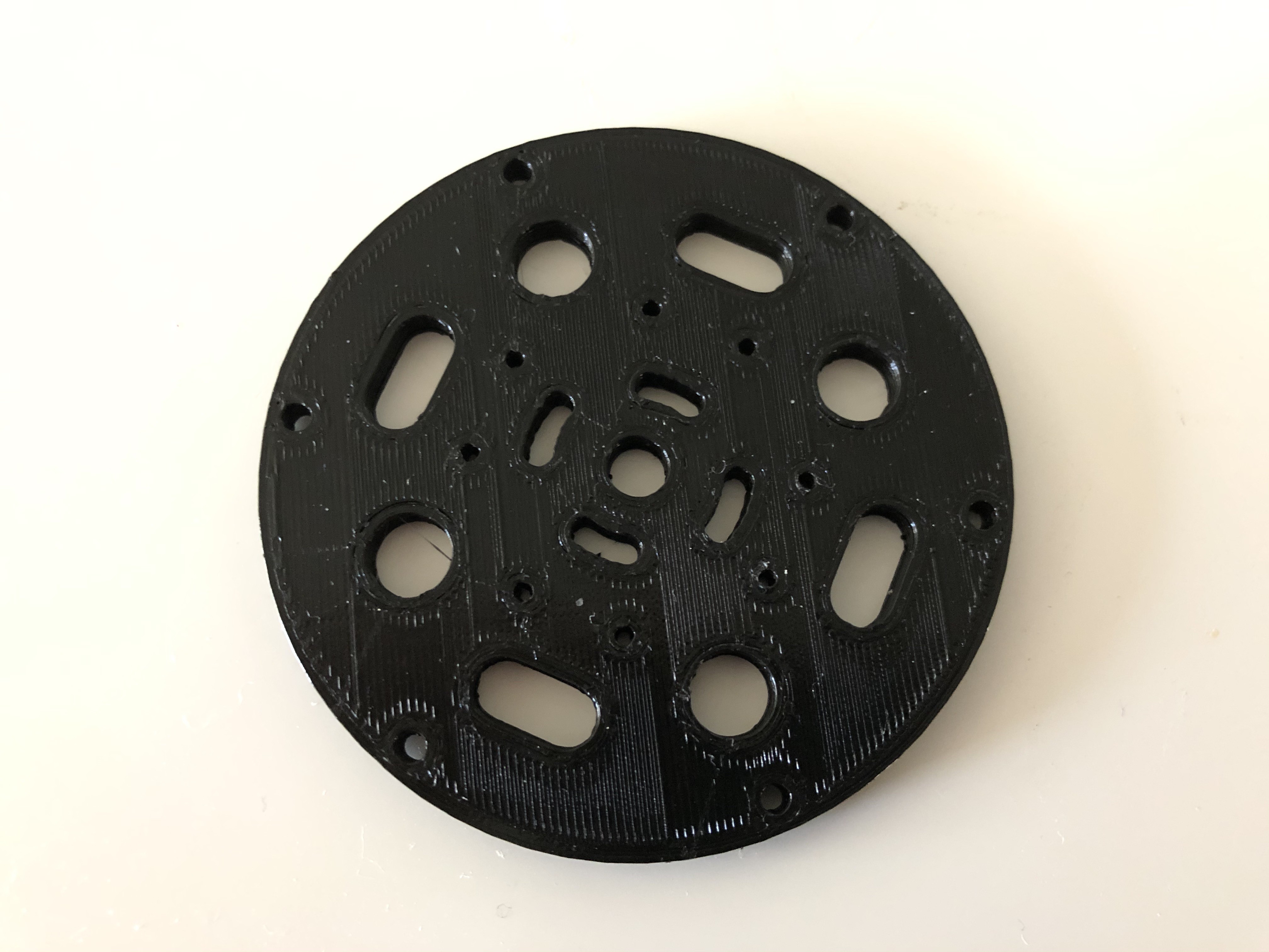
  • 3D printed with minimum hardware
  • Easy to get hardware from aliexpress or amazon
  • Price target < 50$
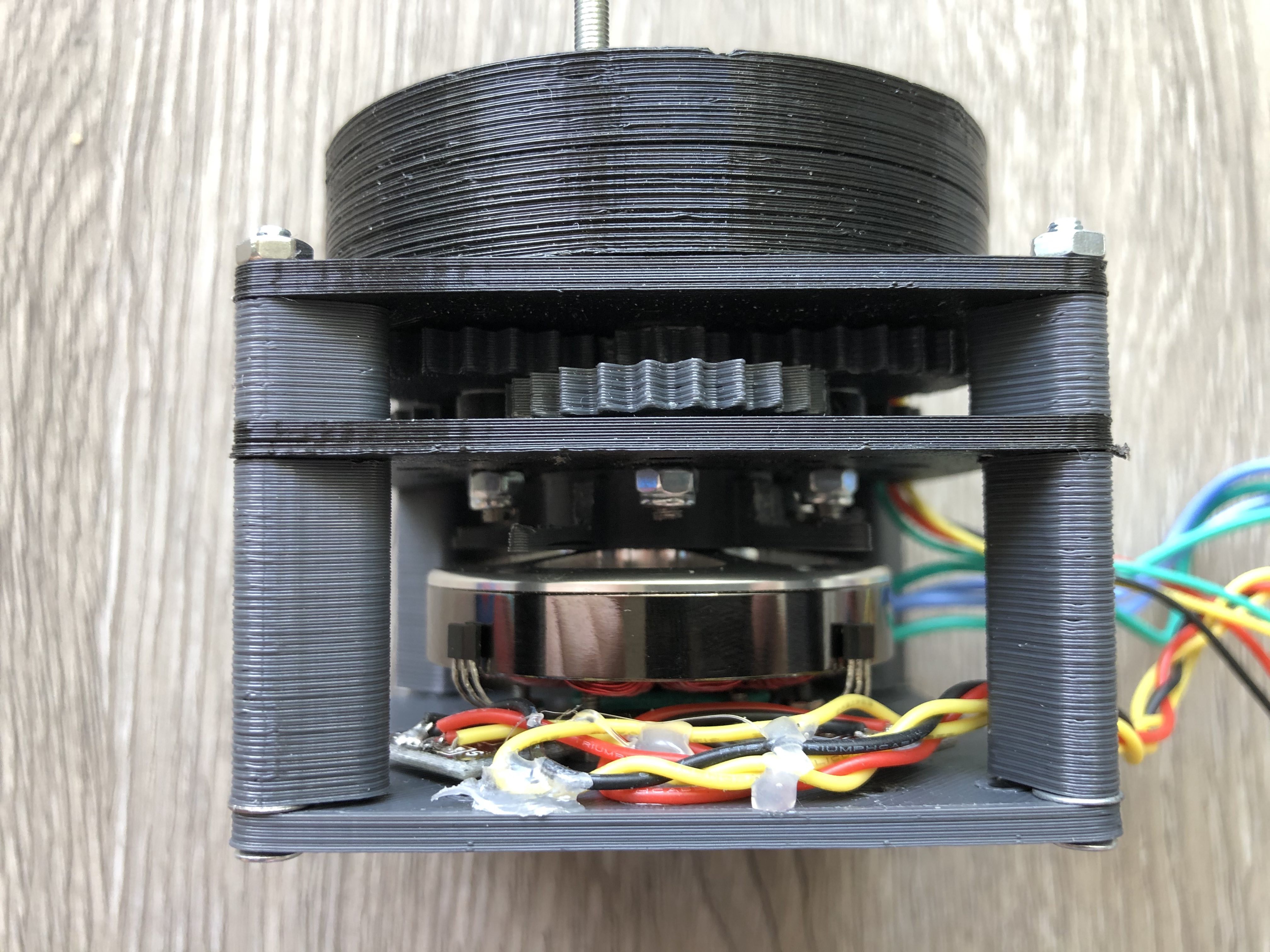
  • Compact (at least actuator itself, electronics can be outside) - my target is a 70x70 for footprint - height is 64mm
  • Lightweight (currently 299g)

  • 1 × 5010 Brushless motor
  • 1 × 28 AWG wire
  • 1 × Arduino Nano or compatible
  • 1 × 2 analog linear hall effect sensors (I use 49E)
  • 1 × Arduino Nano

View all 7 components

  • Working leg prototype

    Pavel G.08/29/2020 at 00:45 0 comments

    Leg prototype

    Key updates:

    • Single arduino can control 2 servo (my plan for 4 per arduino) - 0.7 ms per update now
    • Leg Kinematic seems like ok
    • Python test app

  • Leg prototype

    Pavel G.07/25/2020 at 19:33 0 comments

    Leg kinematic prototype

    Upper and lower links are 150mm each

  • Electronics update

    Pavel G.07/14/2020 at 18:05 0 comments

    Update:

    I switched from L298N to TMC2130 SPI stepper drivers.

    TMC2130 biggest advantages:

    • Size
    • SPI mode to control coils directly via XDIRECT
    • Less wires - now i can control 4+ motors/servos with single arduino nano

    My current setup:

    • Arduino Nano
    • 16CH A/D MUX HP4067 - to get values for up to 16 hall sensors (up to 8 motors 2 halls per motor)
    • TCA9548A - to get data from 8 absolute encoders (AS5600 i2c devices)
    • TMC2130 SPI drivers

    Experimental PCB's

    Left PCB for 4 motors drivers, right PCB is a base for motor with hall sensors and mounting holes

    Auto calibration finalized, calibration results saved to EEPROM

  • Stator wiring machine

    Pavel G.06/26/2020 at 19:06 4 comments

    To rewire motors(very boring process if done by hands) i made a simple machine.

    Details:

    Final result:

  • Gearbox v.1.1

    Pavel G.06/07/2020 at 23:08 0 comments

    2 Weeks spent for Gearbox V 1.1

    Whats new:

    • Dowel pins
    • Herringbone gears used
    • Ratio 1:30.8148

    More updates coming soon...

  • Gearbox

    Pavel G.05/07/2020 at 23:58 0 comments

    General

    I decided to develop gearbox with ratio from 1:25 to 1:35 to archive 180 degrees per second with full torque (i hope).

    Small backlash is acceptable (at least for robot leg actuator)

    All designs will be created in Openscad.

    Design

    I  had a few experiments in the past: So my favorite designs are: 

    1) Spur Pinion  double gears organized in 3 gears per stage (each stage is a 3 spur-pinion gears at triangle corners) with ring gear as output: Openscad drawings and visualization will be uploaded soon.

    This type of gearbox have 1:33 ratio (can vary, but not limited at max)


    2) Cycloidal - i experimented in past, I got 1:25 ratio (strong limit for 70x70 cm footprint), but my past experiments had some Issues (mostly because of missing bearing at critical places)

    Best ideas for Cycloidal you can see here: 

    https://hackaday.io/project/165653-3d-printed-robot-joint-with-active-compliance

    https://hackaday.io/project/167855-simple-cycloidal-robot-leg-for-quadruped

    Gearbox exploded view concept

    Key features: 

    • Ratio: 1:33.1852 (1st stage 1:2.66, 2nd 1:2.666 output is a 1:4.66)
    • Output gears module can be bigger then stage modules
    • Gear height can be different for each stage
    • Place to embed as5600 i2C absolute rotary sensor (2$ on aliexpress)
    • Extra stage can be added without problems (1 extra stage and you can get 1:88 ratio)
    • Only output stage is rotate (all double gears are rotates on the static common shafts)
    • Each stage have 3 points of contact (less backlash and more torque)

    Gearbox disassembly video

    Assembled gearbox

    Actuator test without absolute encoder

    Gearbox test with absolute encoder

  • Motor

    Pavel G.04/29/2020 at 08:10 0 comments

    Motor theory and practice

    I use brushless 5010 motor rewired as stepper motor with 28 steps per revolution, controlled by L298N module, arduino and 2 hall effect sensors

    Image bellow is a 3 phase brushless motor (5010 model) with 14 magnet poles and 12 stator poles, this motor need to be rewired as stepper motor with 28 steps per revolution

    Motor wiring diagram (14 magnet poles, 12 stator poles) converted to stepper motor (top view)

    NOTE: Arrows lines is always on top of stator lines

    Motor phases animation with wiring above visualized in video bellow

    Disassembled motor ready for rewire

    I use small radius PTFE tube as a helper for rewiring

    100 turns per pole by 28 AWG wire (very challenging process) 

    Final resistance 3.7 Ohm per phase

    Assembled motor (wires covered by nail polish (pole 1 marked by blue)

    Motor base plate 3d Printed (small holes for hall effects sensors mounting)

    2 Hall sensors ready to be mount on base plate (49E 9148G sensor)

    Sensors mounted to base

    Motor mounted to base plate 1st hall sensor look at stator pole 12 2nd to 9 (it should be 90 degrees)

    Sensorless motor test run

    Sensored test run

    Motor torque test 

    • 160 PWM - 70g/10cm or 700g/cm
    • 255 PWM - 160g/10cm or 1600g/cm

View all 7 project logs

Enjoy this project?

Share

Discussions

Similar Projects

Does this project spark your interest?

Become a member to follow this project and never miss any updates