 Supplyframe DesignLab
THE PROBLEM
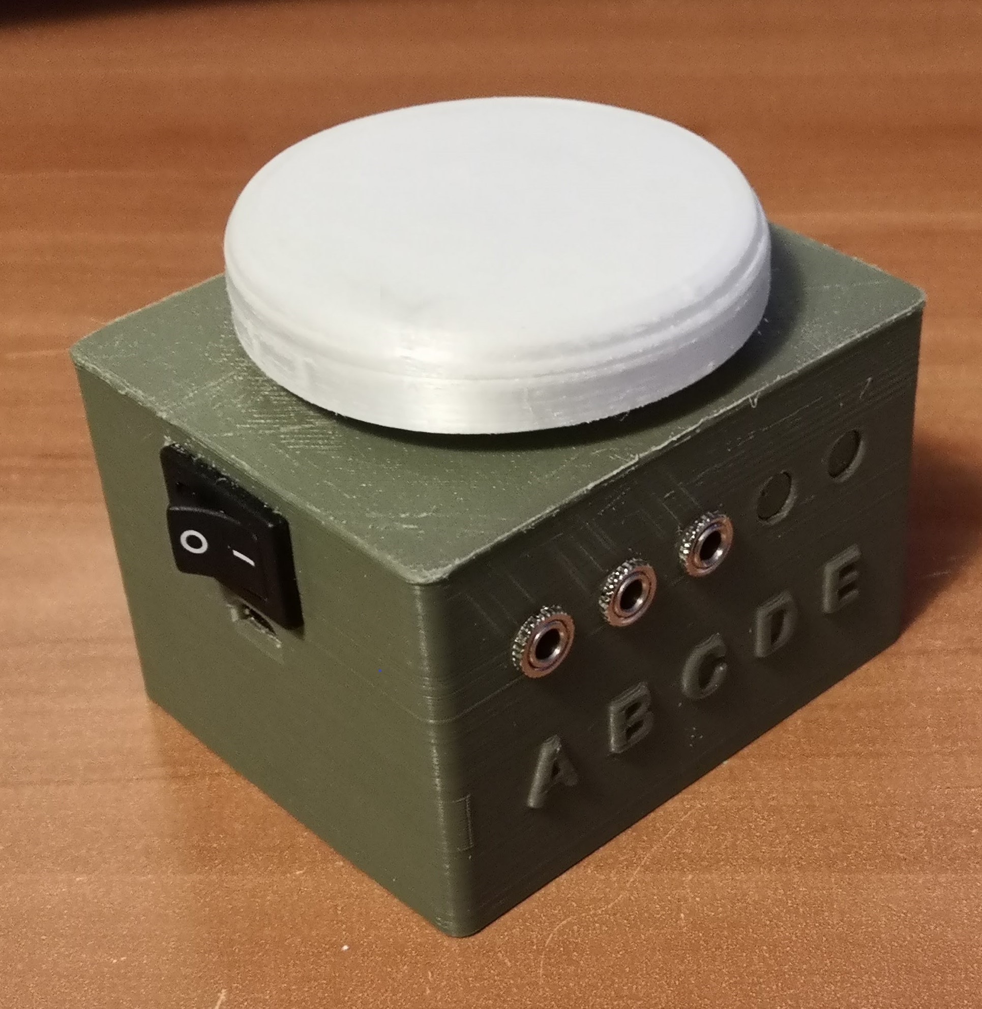
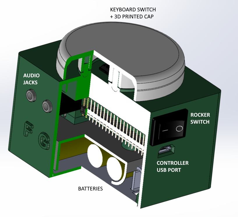
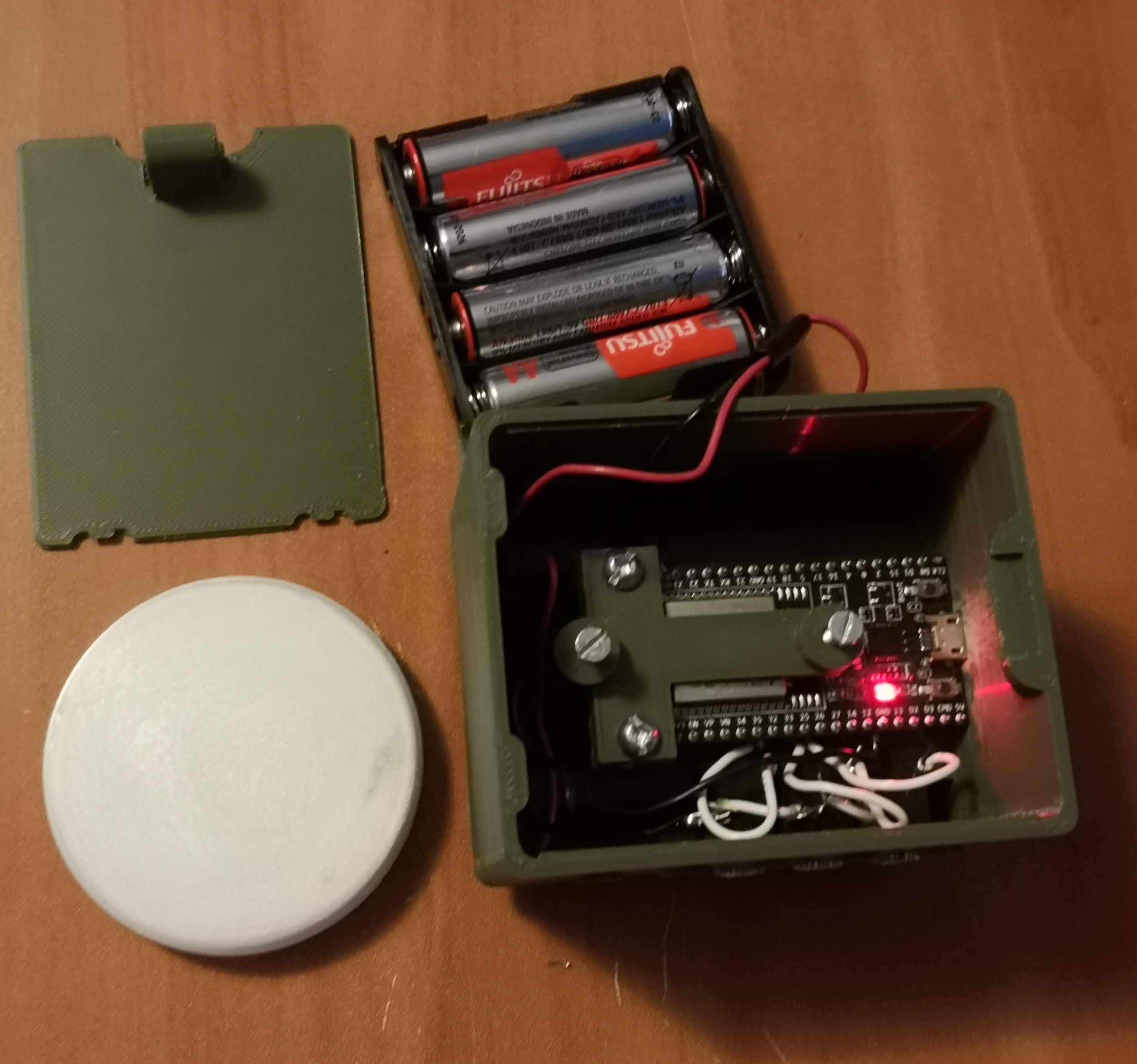
Even though assistive technology (big buttons, joysticks, etc.) is meant to help individuals with cerebral palsy interface with digital devices, they are still difficult to use and lack utility due to the limited integrations with electronics. Commercial assistive technology is expensive and limited in options, meaning the generic models are not suited for each individual and their unique circumstances.
THE GOAL
To develop an affordable, inclusive, “universal” assistive technology platform for individuals with cerebral palsy (and other conditions) to help them easily access the digital world. The word “universal” can be viewed from two perspectives. 1) The platform can be used by all individuals. 2) The platform can be used to control any electronic device.
Though these goals are unrealistic in the timeframe of a 2-month project, the specific aim of this project was to lay the groundwork of an open source project that can be developed further to achieve these goals.
THE DREAM
To close the digital accessibility gap between the general population and the cerebral palsy population. With this project, we want to give individuals with cerebral palsy greater individuality and be more capable of making positive contributions to society.
PROJECT MILESTONES
MILESTONE 1: Initial Abstract Proposals (July 17, 2020)
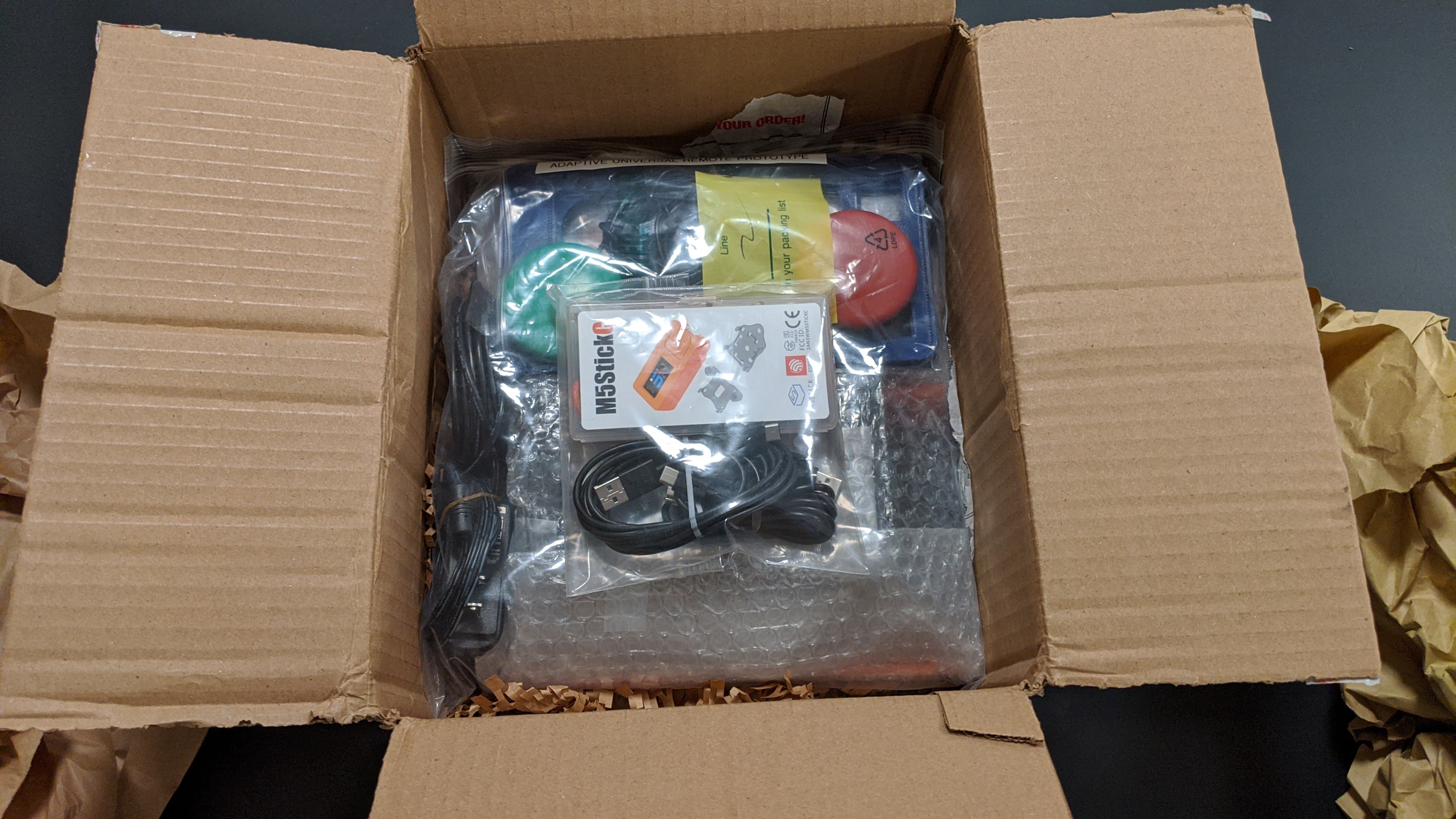
MILESTONE 2: First User Testing Session (August 17, 2020)
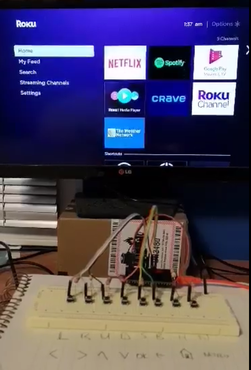
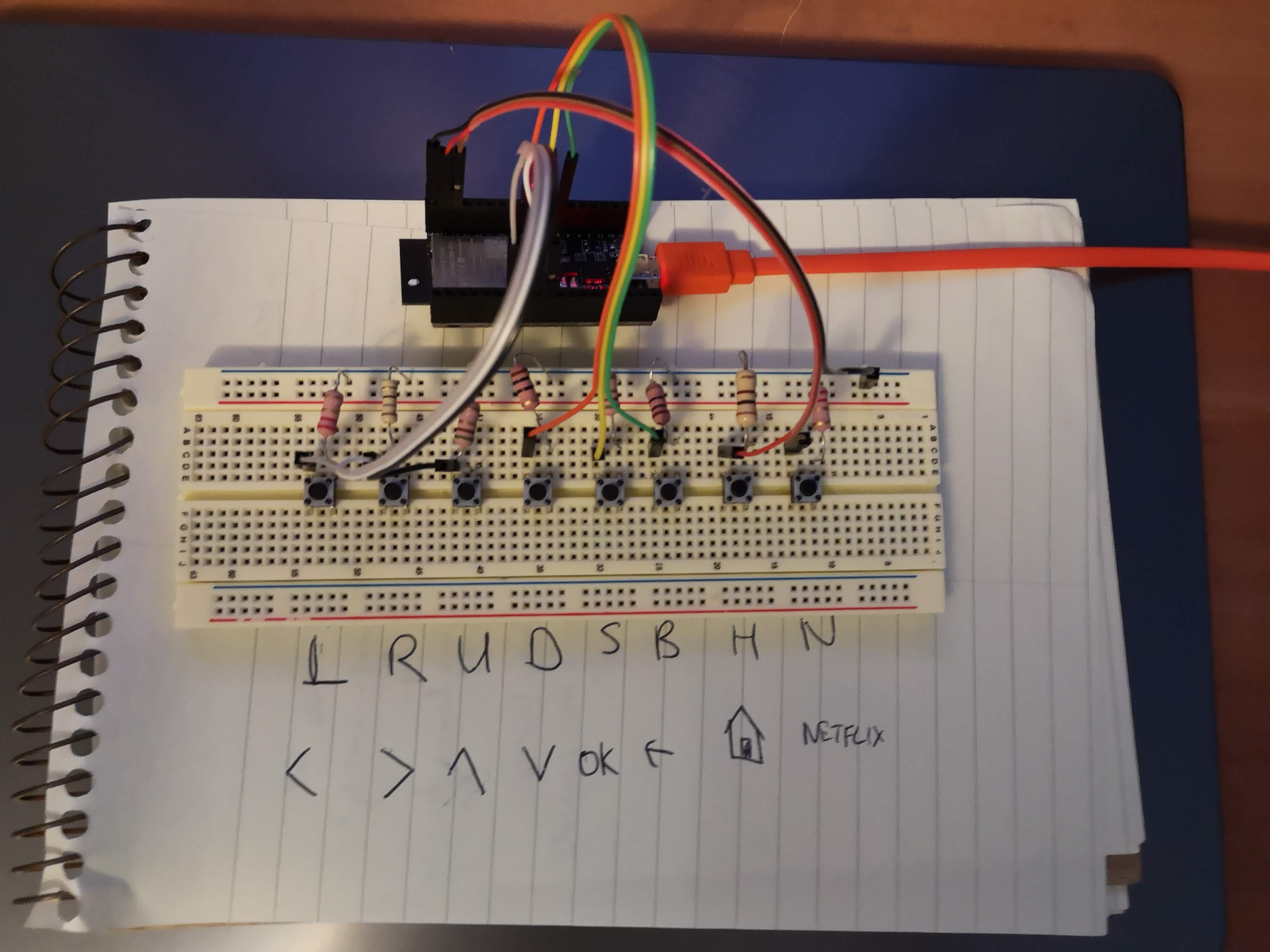
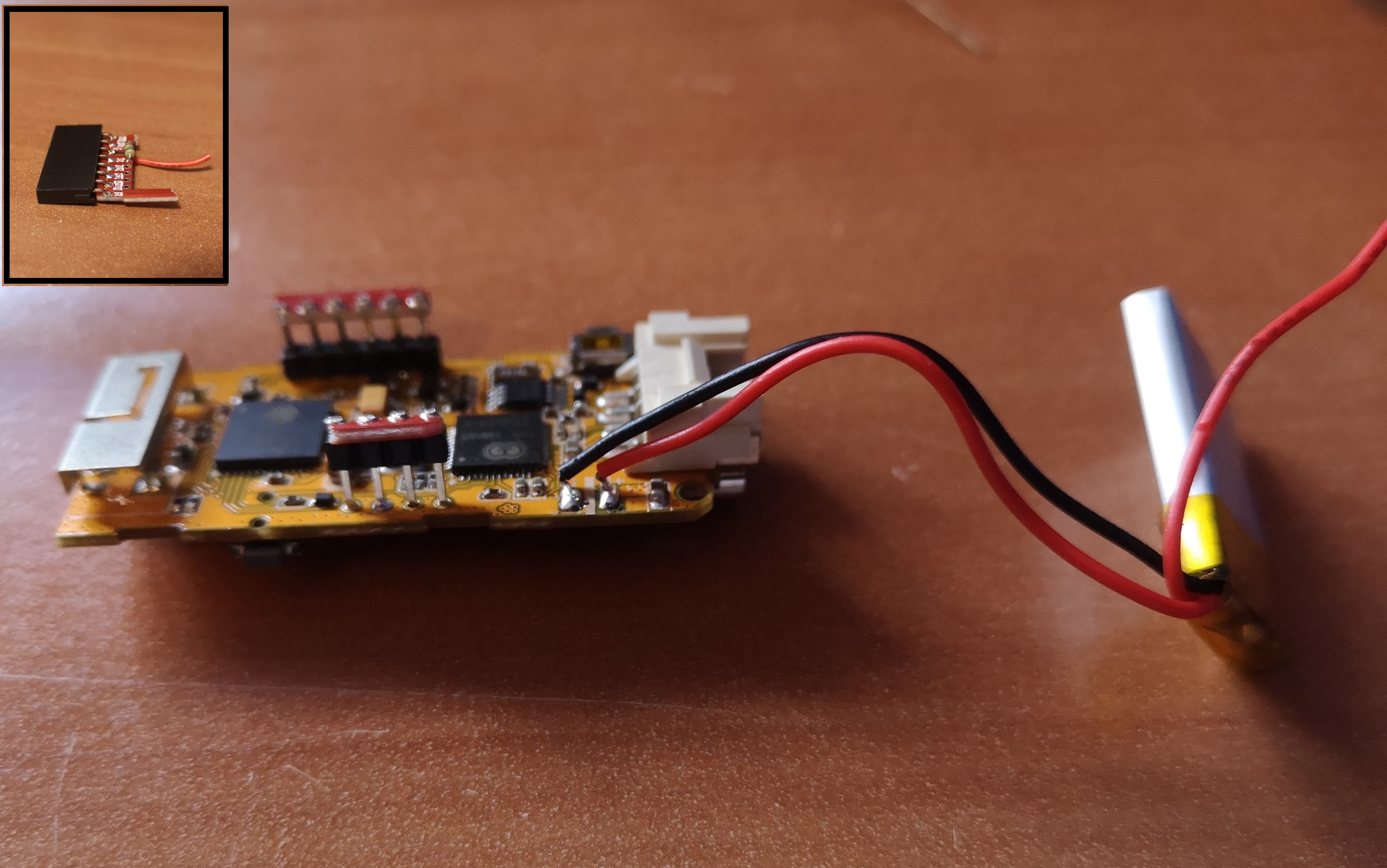
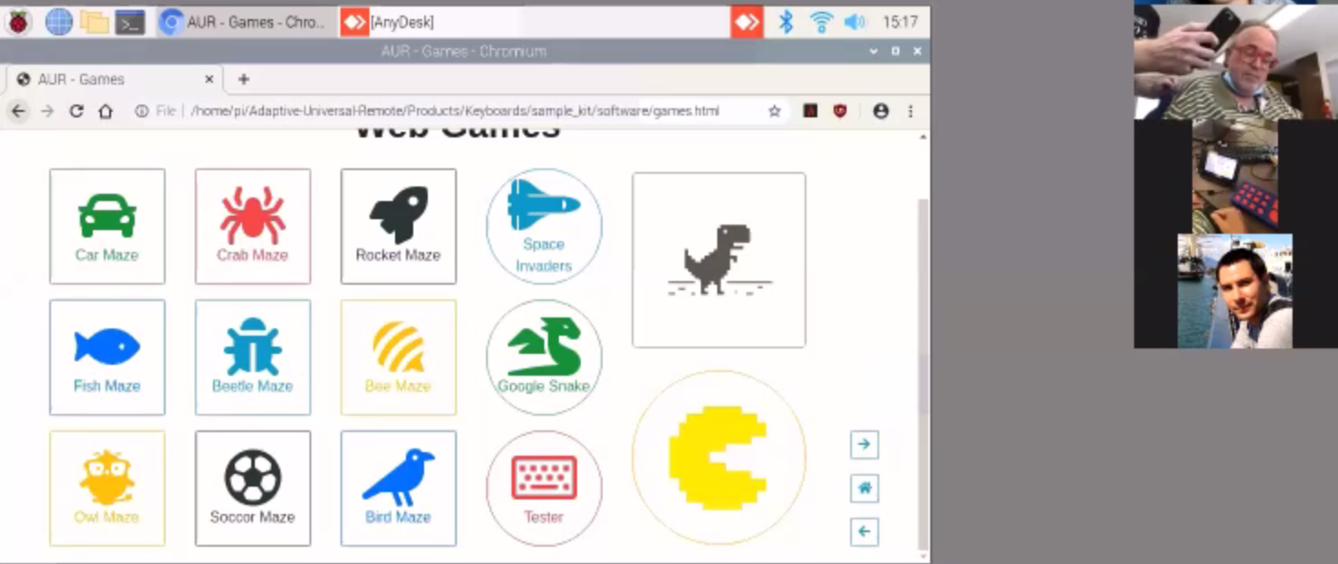
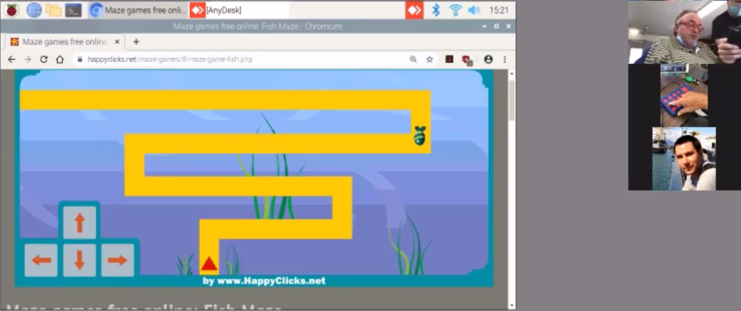
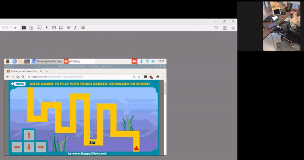
About a month into the project, the initial prototypes were shipped to UCPLA for initial testing. Shortly after, we had our first user testing session over Zoom, which we were really grateful for and allowed us to quickly realize our project oversights up until that point. A follow up testing session was conducted a week later to gain further feedback regarding our initial prototypes.


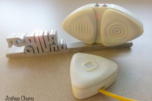
 Joshua Chung
 dariocose
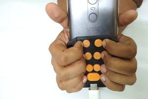
 Vijay
Vijay
 Animesh Chattopadhyay
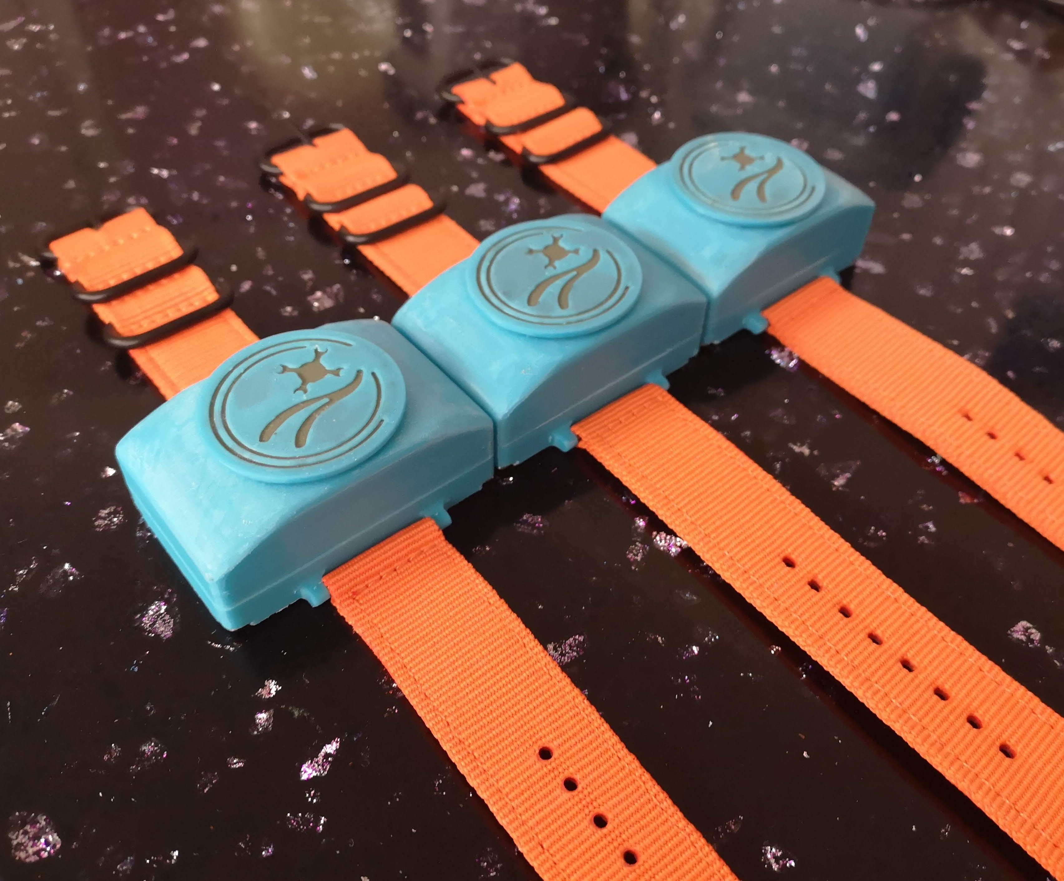
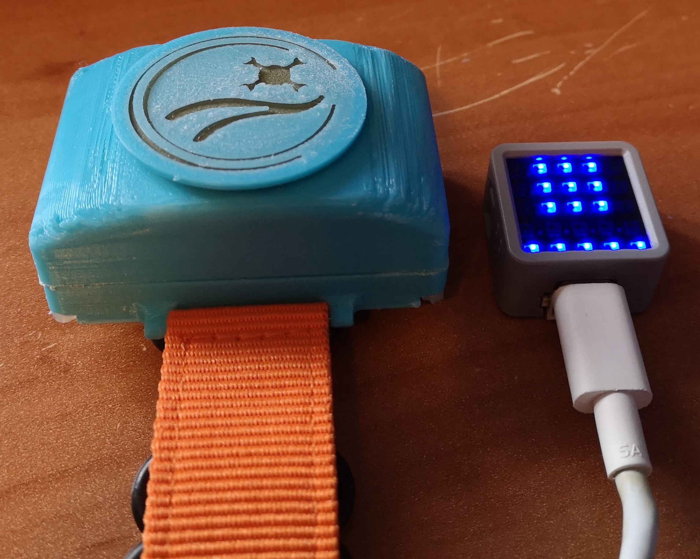
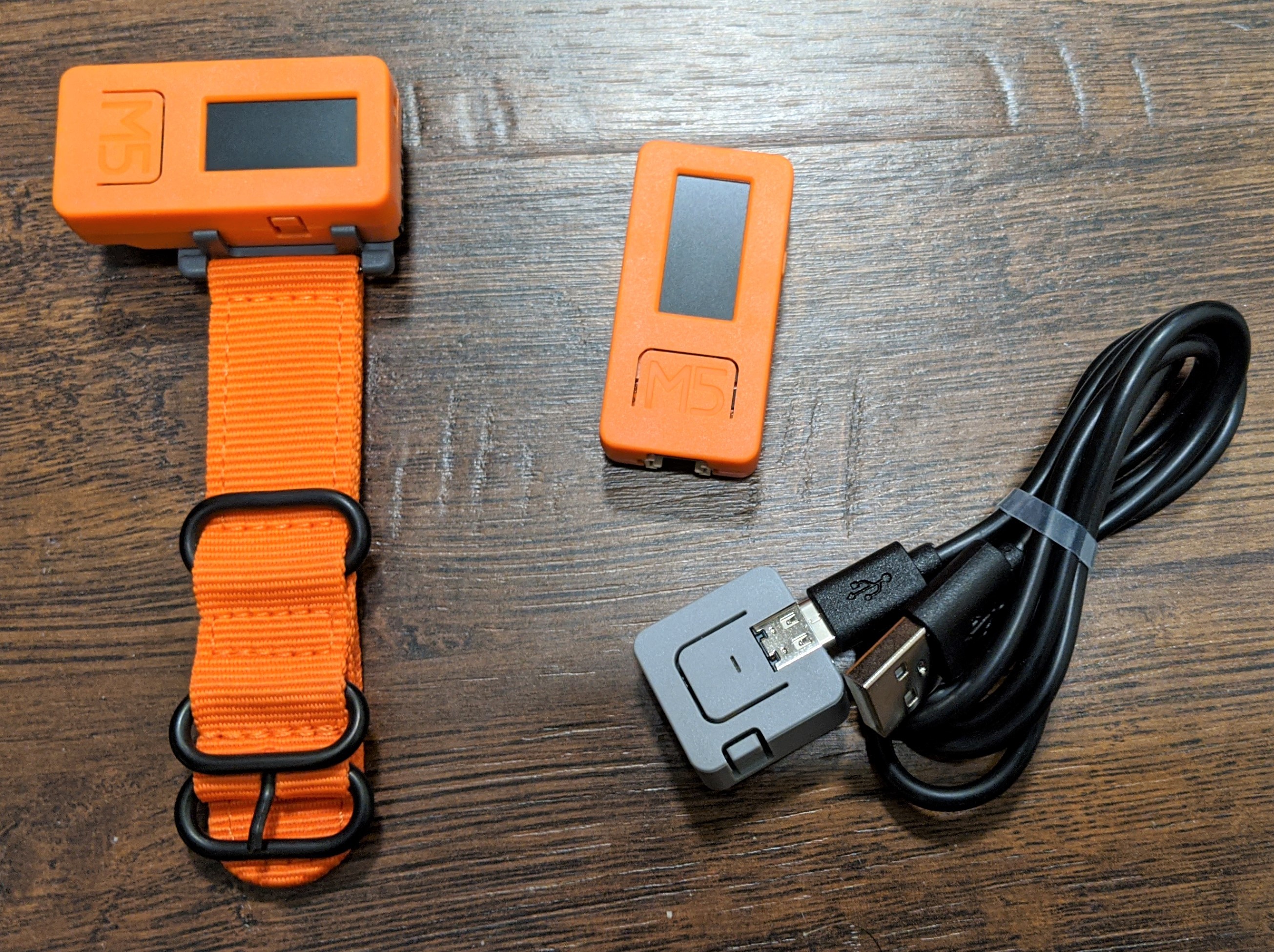
Out of curiosity where are the watch straps obtained?