Close
0%
0%

Soft Soldering Jig

Circuit sculpture jig consisting of a vacuum pump attached to a silicone pad to keep rods and SMD components in place when soldering them.

Public Chat
Similar projects worth following
This is my attempt at building a versatile jig for soldering components used in circuit sculptures. Since silicone is moldable, compliant, and quite heat resistant it seemed like a great material for this project.

The other feature of this jig is that when vacuum pump is attached it is possible to hold SMD components in place. When soldering SMD LEDs for instance I found that quite often the LEDs would stick to the solder blob on the soldering iron instead of to the brass rod it was supposed to.

Files to generate this jig's 3D printed mold are made in OpenSCAD. For this project I tried something new and named all variables after parts of a city, since in my mind the jig greatly resembles one.

NOTE: technically the silicone used is not rated to use at this high of temperatures. It is a trade-off I want to take into account in the technical details section.

Background:

When hackaday announced the circuit sculpture challenge in august I was very excited. I was already impressed by Mohit Bhoite's sculptures on hackaday and his interview on embedded.fm (ep 314) really encouraged me to give it a try. So what better excuses than a hackaday contest.

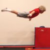
Never having made a sculpture before I thought it be wise to do a basic tutorial for one first (the link in the embedded.fm shownotes was very helpful). Trying things for the first time not being challenging enough I thought it would be fun to try this as a date.

On this date we learned the following:

  • Cutting mats are not heat resistant
  • You will need up to 4 hands to complete some connections
  • Double sided tape is not ideal.
  • SMD LEDs like to stick to soldering iron tips
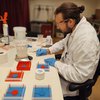
  • Soldering is a fun date activity

Most circuit sculpture tutorials recommend holding parts in place with double sided tape. However the heat of the soldering iron will reduce the stickiness of the tape (to not sticky at all anymore). So the need for a solder-able hold in place method was born.

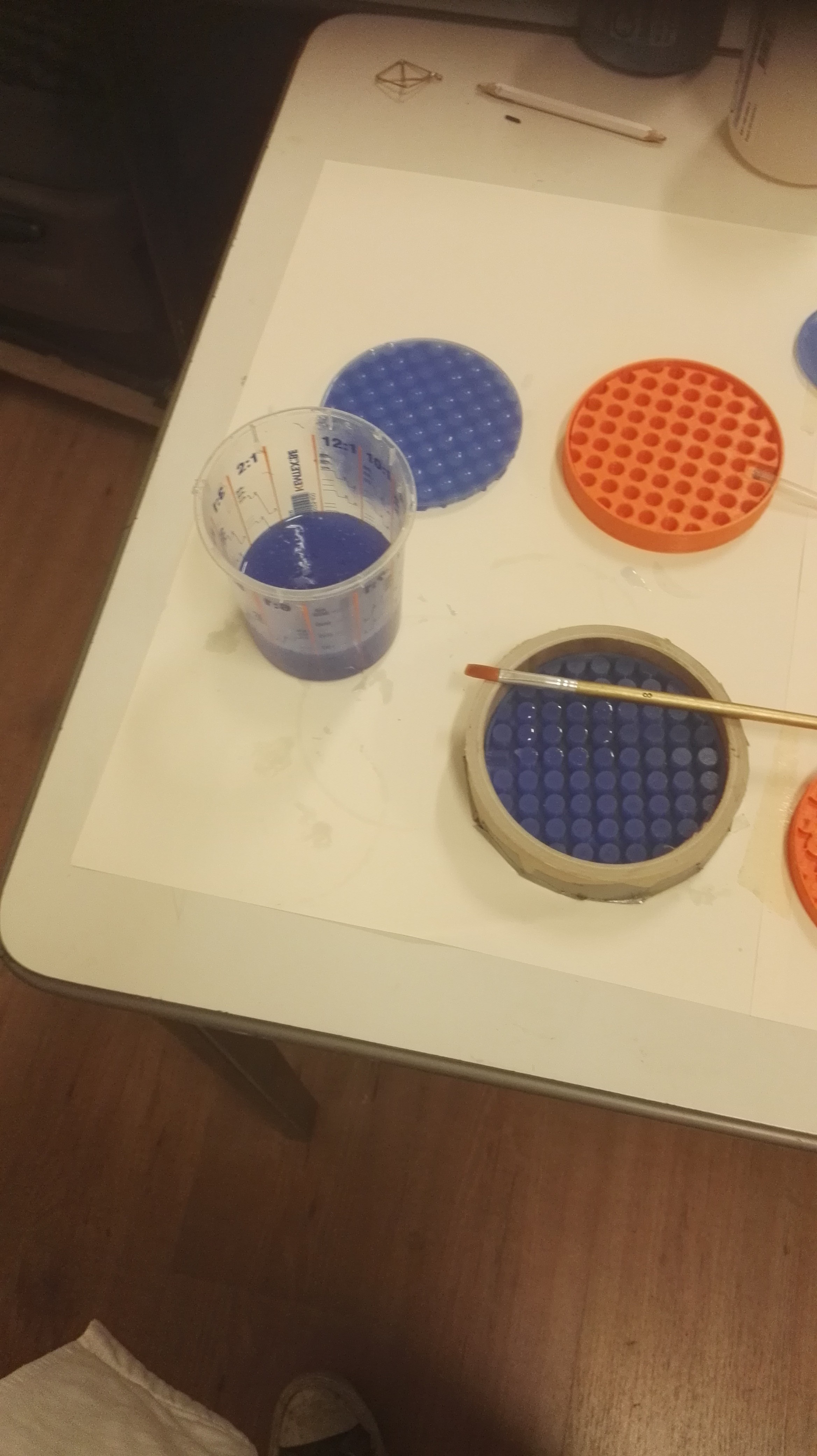
I like to hobby a lot with soft robotics projects which (for me) are made of silicone. Because silicone is quite heat resistant the idea of using as a jig cam e to mind. When pouring silicone you will almost always have a little left over which pools at the bottom of your mixing cup. When this eventually sets it forms a nice round complementary soldering pad. Trying to make another one of Jiří Praus' LED jewelries, but this time on my own, worked quite well even with just a flat silicone pad.

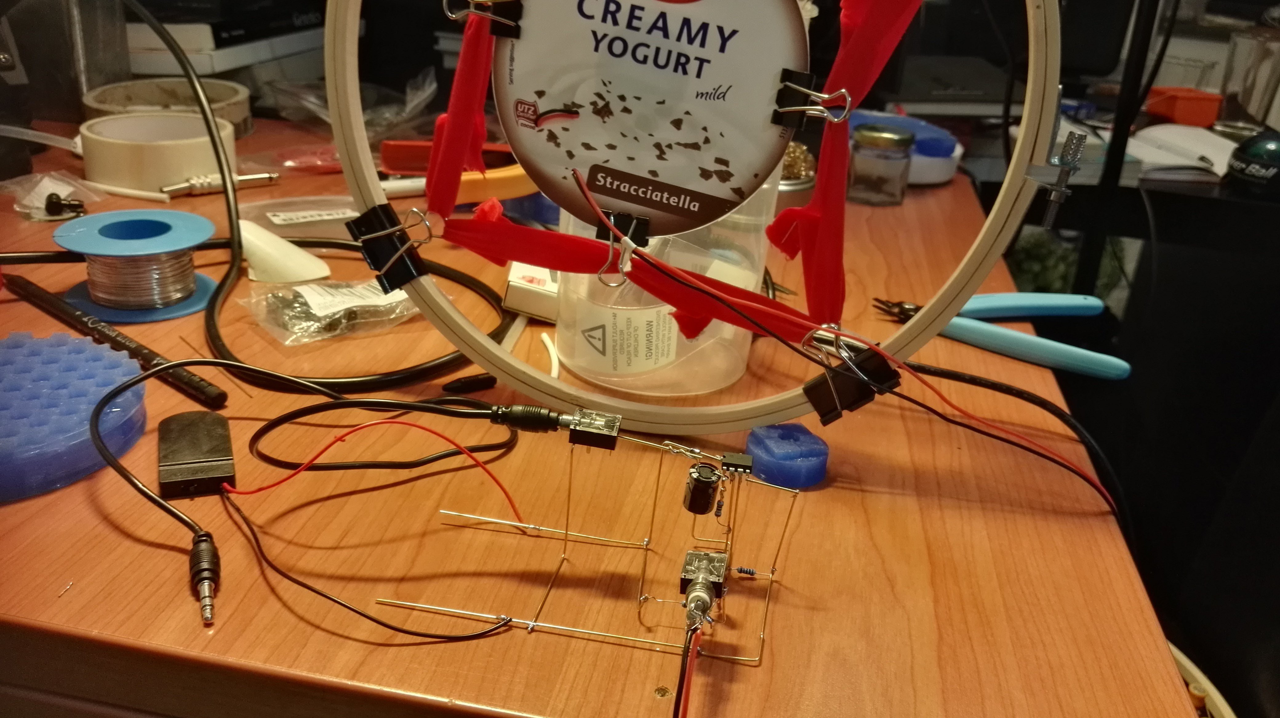
Since its possible to shape silicone in many ways when you actually pour it into a mold (instead of leaving it in the cup); the idea of making a pattern to hold the brass rods in place started to form. Later the realization came that the air pumps I was using for my soft robotics project could be used to create suction to keep SMD components in place.

Leading to the project page we are on now. I had a complicated idea for a circuit sculpture in mind for the contest, however working on the jig itself became quite interesting and challenging. I also hope that by making this project page I can receive some input from other circuit sculpture builders. Mainly about what parts are often used and difficult to work with without a jig, also for which orientations solder support is appreciated. Plus feedback on the OpenSCAD is also appreciated. I am really curious what people think about the variable naming scheme, since I'm personally really fond of it.

OpenSCAD file

Naming scheme for variables is based on parts of a city. Code is now on Github, though it still needs development in order to produce a useful jig.

Variable names above ground
Variable names underground
OpenSCAD variables (above ground)
OpenSCAD variables (underground)

Keep in mind that the current physical build is far from perfect. The 3D model code is also quite inefficient since it takes both a long time to render as well as to preview. The concept of this jig is great, however there is a lot to improve before it's ready help anyone. But I believe the soft soldering jig can help with circuit sculptures.

Model versions

V0

This was the prototype version, to see if the concept even works. Area is deliberately very small for rapid printing and less silicone use. The airflow works and keeps 1206 LEDs in place. This jigs is surprisingly useful already. Even for non circuit sculpture stuff like soldering wires to each other.

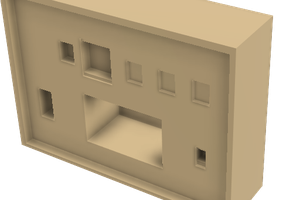
Mold consist of 2 parts. The cylinder containing the city topology and a plug to be inserted to claim the space later occupied by the air tube. Plug can be held in place by elastic band.

V0 jig modelV0 mold and result.
Render Jig V0
Complete overview V0
Left: Silicone jig right: mold

V1

First full scale design. with lots of manholes for air intake. Unfortunately it could not create any suction since there where to many manholes.  The bigger surface is great to keep longer rods in place.

Made with both shore 8 and shore 15 silicone. Both having a nice firmness. Though people seem...

Read more »

Portable Network Graphics (PNG) - 565.68 kB - 11/09/2020 at 16:20

Preview
Download

  • 1 × Silicone (160g / 130ml) Shore A-8 or A-15. Just get 1kg its good stuff.
  • 1 × Silicone Oil To use with shore A-15 silicone to make it more flexible (lesser shore value)
  • 1 × PLA filament To use with 3D printer when printing molds.
  • 1 × Silicone tube To connect air pump to jig.
  • 1 × DC Air pump 6V Make sure that it has a inlet for air suction, check if you can connect 2 tubes. Sometimes these are revered to as vacuum pumps or breast (milk) pumps

View all 11 components

  • The big recap post

    Inne04/16/2023 at 21:37 3 comments

    Note

    This project log is for everyone that wants to know what happened with the soft soldering jig since the last update. If you are mostly interested in the newest files please hold out for a bit; in the coming week I will be publishing the files for version 3 (v3) of the jig.

    Renewed interest

    It is good to be back. After being featured on the Hackaday blog and podcast (ep213) last week, my motivation has very much returned. Since I last submitted something, in 2020, I have been working on and off on this project doing bits and pieces. This post is to catch up with what has happened since then, what works, what needs improvement and what my goals are for this project. Sprinkled with a bunch of pictures to keep it entertaining.

    Festivals and talking to people.

    In 2020 this project won a prize in the special category (best jig) of the circuit sculpture contest. It was a really validating experience, and really felt like something I made was appreciated and celebrated.

    In the years after, I kept taking the jig to Makerfestivals and Hackercamps. Both to solder on and to show as part of my portfolio. They came in handy many times, though not as often yet to make actual circuit sculptures.

    One of the coolest things was when someone asked me if this could be used to mix fluid droplets for microscope. We tested it on the spot, and it worked pretty well. It was really interesting to hear the feedback, whenever I showed the soft soldering jig.

    All and all, I am very happy I wrote up this project page. Consistent writing and documenting doesn’t come natural to me. However, having all the files and photos in one place, somewhere that you can point someone to, has been great. I am glad I did it, and can recommend to everyone making a project to give it a try and see where it goes.

    Inne giving a presentation in front of a screen showing the Hackaday IO page of the soft soldering Jig. The audience at the bottom is mosaicked out
    Picture 1: Giving a lightning talk during Hackaday Berlin 2023, that kicked of the renewed interest.

    A look at the technical side

    Time to look back on the Hardware. As of posting, there are 3 versions of the jig, v0, v1 and v2 with v3 coming shortly. V0 is cute, small and has working vacuum. V1 is the main design, has top and bottom layer and doubles as fidget toy. For v2, the mold has brass rods inserted, instead of 3D printed ones, they make me less sad when they inevitably break in transport, as opposed to v1. The following are the lessons learned along the way.

    The vacuum suction system

    As it stands, the vacuum system is a major failure. The core principle doesn't work, it was supposed to hold SMD components in place so they wouldn’t stick to the soldering iron. There are however too many (man)holes to create proper suction. You would need to cover all of them. Even with the v2 model with fewer holes, you would still need to plug them all, which is too much work.

    Initially, I was hoping the air pumps would be strong enough, and the (man)holes tiny enough, that the suction was sufficient. However, even once you plug all the holes, the silicone is too flexible to withstand the vacuum and will cave in.

    Therefore, the SMD hold-in-place system needs a redesign. This can be either vacuum or something completely different. Since there are other, more pressing, design challenges; I decided to remove the complete underside from the jig (for v3). Even though, suction does work for v0. Removing the underground saves a lot time on production and makes everything easier to work with. See Picture 2 to get an idea of what assembling them involves. It shows connecting the top (above ground) and bottom (underground) parts for jig v1.

    The silicone parts of jig v1 not put together yet. Circular jig holder being made on a cutting mat. Electronics bench with finished jig v1, airpump connected to powersupply reading 11.7 volts.
    Table silicone jig parts being glued together by brushing more silicone. Table filled with just poured jig v1 molds, plus other equipement. general overview 
  width= 270
  title=
    Picture 2: Assembling jig v1. a) Both halves of the silicone for jig v1. b) Make shift tool to center halves on top of each other, a cardboard tube happened to same diameter as the jig. c) Example of pouring the (other) parts of the mold, left over silicone goes in v0 molds. d)...
    Read more »

  • Soft soldering jig in action

    Inne11/10/2020 at 02:19 0 comments

    TLDR: Made an audio amp just look at the pictures.

    Realizing that I haven't really posted anything about this jig in action, I took the opportunity to make this post. Not making an actual sculpture for the circuit sculpture contest left me a bit without pretty pictures. Though I actually use this jig quite often for soldering wires and components (i.e. non circuit sculpture activities). Thankfully the Remoticon gave me a nice opportunity to take some pictures of an audio amp I build.

    During the remoticon I joined the "finding sound and making microphones" workshop. Part of the workshop involved making your own mic using a piezo element. On the required materials list was an audio amplifier which I managed to source before the workshop. However it turned out to be very much broken when I retrieved it from its packaging.

    This being at noon while the workshop was in the evening it left me some time to build up anxiety about failing to meet the requirements. But also time to remember that I bought some LM358P OpAmp ICs once. At the time they were to complicated but turned out to be super welcome right now.

    I googled a diagram for an audio amplifier and tried to match the value of the passive components as best I could. Which turned out to be only a capacitor that was 4.7 uF instead of 10. Starting with one of the LM358 pins I followed the traces in the diagram, adding parts as I encountered them. Sometimes having to take a minute to think how the pins/traces will interact, but overall its a quite relaxing experience. Even if you don't see the appeal in making pleasing art, I would definitely recommend you give this kind of "sculpture" a try. If only to experience this method of "getting things done".

    In the evening the workshop came around. I will not pretend that this method saved my bacon, because at the time I was too scared to plug it into my computer. Luckily the piezos provided audible sounds even without amplification. after the workshop I spend some time finishing the mic and while staring at my brass rod structure masquerading as an amp I couldn't resist the urge to finish it and plug it in. To my complete amazement It turned out to be actually functional. The amp even boosted the mic in such a way to allow me to sit at an comfortable distance away from it.

    Moral of the story. I guess that it is useful to have a general purpose soldering tool/jig. It feels amazing to promptly finish something with parts you have lying around. And please take a look at the pictures.

    Building an audio amp 1
    Building an audio amp 2
    Building an audio amp 3
    Building an audio amp 4

View all 2 project logs

Enjoy this project?

Share

Discussions

WestfW wrote 11/19/2020 at 07:43 point

You might ask yourself, as I did: "How about Silly Putty?  Isn't that a silicone-based thing that might hold up to soldering temperatures long enough to be useful for tacking things in place?"

The answer seems to be "No", at least WRT the sample I tried (it was actually a "Chameleon" "Thinking Putty" that I happened to have around, so it might not have been the best choice...)  :-(

  Are you sure? yes | no

Inne wrote 11/19/2020 at 09:15 point

At first I thought you meant poster putty, which is quite excellent for soldering. Used it a couple of times on festivals etc. though never directly under the part I was soldering.

If I had to guess I would say silly putty might not work as well because of the stuff mixed in to make it malleable . They might not handle heat as well as the silicone does. It is awesome though that you already tested it, what happened did it burn, smoke, or become brittle?? It might also be due to there being a lot of slime variants, being toys or erasers etc. so the exact composition might be hard to verify (i.e. amount of silicone in it).

While putty can be great for soldering the point of this jig is more to have something versatile that you can grab from a shelf. Just place you components solder away and retrieve them easily without adding extra stress on the joint. To be used repeatedly without having to put a lot of extra effort into it.

  Are you sure? yes | no

WestfW wrote 11/21/2020 at 02:43 point

It softened excessively, sort-of foamed a bit, and left some residue on the iron.  The lump of putty seems to recover pretty well...  Could be fillers or pigments, as well as plasticizers or the grade of silicone oil used (IIRC, it's made from silicone oil, which is not likely to need "malleability additives.   OTOH, I seem to recall that Borax is a common cross-linking agent (turns "oil" into "putty"), and borax itself is a flux (although usually at higher temperatures than electronics soldering/)
(This particular silly putty variant does claim to be silicone based, but I don't have any idea how much "other stuff" is in there.)

  Are you sure? yes | no

WestfW wrote 11/26/2020 at 10:52 point

I found some "genuine" silly-putty, and it behaves the same as the other stuff...

  Are you sure? yes | no

Inne wrote 11/28/2020 at 17:58 point

Ah unfortunate. When I read on the silly-putty wikipedia that it was described as designed to be heat resistant I was a bit hopeful. Guess there is a big difference in withstanding 200 degree (C) constant environmental temp and 350 (C) focused and applied heat from a soldering iron. Tough to its credit it didn't ignite and failed gracefully which is something.

Fortunately the pouring silicone works well, so maybe it's time to buy some of that stuff ;P.

  Are you sure? yes | no

WestfW wrote 12/30/2020 at 10:22 point

Ah.  I decided to experiment with "other" "silicone putties" that might exist.
This stuff holds up to molten solder just fine: https://www.amazon.com/FUSING-900-Moldable-Silicone-Putty/dp/B07RV5R33Y
(i've got my iron set to 350C, which is well above the 500F that it claims to withstand.)
Not as common as silly putty, but not to outrageously priced, either.

  Are you sure? yes | no

Inne wrote 01/06/2021 at 19:33 point

Honestly I am really happy that your perseverance proved fruitful. Well done. This putty also seems pretty useful, I am thinking about picking it up as well. Things like this are always good to have in your arsenal.

  Are you sure? yes | no

Michael Welling wrote 11/07/2020 at 06:30 point

Nice project. Thanks for sharing at table 4. I now fully understand and am sorry for the regular PCB application tangent.

Here are some links from the conversation:

https://hackaday.io/project/34160-cyborg-ring
https://hackaday.io/project/19189-diy-vacuum-pickup-tool

  Are you sure? yes | no

Inne wrote 11/10/2020 at 00:40 point

I did really appreciate our (table's) talk, even with the occasional dish washing noises making it hard to listen. I now realize, also after watching the SMD challenges, that PCB soldering has its own difficulties. Maybe deserving its own separate jig/utensils.

Love the cyborg ring though, it made me realize that I should try to put a couple of manholes next to each other for SMD to SMD soldering. Maybe in combination with gutters to solder them upside down.

Thanks for thinking along and posting the references.

  Are you sure? yes | no

Similar Projects

Does this project spark your interest?

Become a member to follow this project and never miss any updates