 Yann Guidon / YGDES
Let's simply start with a simple algorithm pointed to by Wikipedia and that seems to have been widely used :
pseudo-LRU

two-way set associative - one bit

   indicates which line of the two has been reference more recently


four-way set associative - three bits

   each bit represents one branch point in a binary decision tree; let 1
   represent that the left side has been referenced more recently than the
   right side, and 0 vice-versa

              are all 4 lines valid?
                   /       \
                 yes        no, use an invalid line
                  |
                  |
                  |
             bit_0 == 0?            state | replace      ref to | next state
              /       \             ------+--------      -------+-----------
             y         n             00x  |  line_0      line_0 |    11_
            /           \            01x  |  line_1      line_1 |    10_
     bit_1 == 0?    bit_2 == 0?      1x0  |  line_2      line_2 |    0_1
       /    \          /    \        1x1  |  line_3      line_3 |    0_0
      y      n        y      n
     /        \      /        \        ('x' means       ('_' means unchanged)
   line_0  line_1  line_2  line_3      don't care)

   (see Figure 3-7, p. 3-18, in Intel Embedded Pentium Processor Family Dev.
    Manual, 1998, http://www.intel.com/design/intarch/manuals/273204.htm)


note that there is a 6-bit encoding for true LRU for four-way set associative

  bit 0: bank[1] more recently used than bank[0]
  bit 1: bank[2] more recently used than bank[0]
  bit 2: bank[2] more recently used than bank[1]
  bit 3: bank[3] more recently used than bank[0]
  bit 4: bank[3] more recently used than bank[1]
  bit 5: bank[3] more recently used than bank[2]

  this results in 24 valid bit patterns within the 64 possible bit patterns
  (4! possible valid traces for bank references)

  e.g., a trace of 0 1 2 3, where 0 is LRU and 3 is MRU, is encoded as 111111

  you can implement a state machine with a 256x6 ROM (6-bit state encoding
  appended with a 2-bit bank reference input will yield a new 6-bit state),
  and you can implement an LRU bank indicator with a 64x2 ROM
Of course the 1998 link on the Intel website has long been broken but this gives us a first approximation :
- 2-sets uses 1 bit. This can't be more simple or easy and the logic is truly minimal. Go for it everytime you can :-)
- 4-sets is more complex. There are only 3 bits if pseudo-LRU is good enough for you, but true LRU now has to be distinguished and grows as N!, so you'll need 6 bits and a 256-bits ROM.
How can one build larger systems ?
Wikipedia lists many strategies but it is desirable to get "most" of the true-LRU benefits without the size, time and costs.
Logs:
1. 4-LRU
2. 4-way Pseudo-LRU
3. PLRU4
4. MRU mode
5. The other LRU
6. MRU in L1
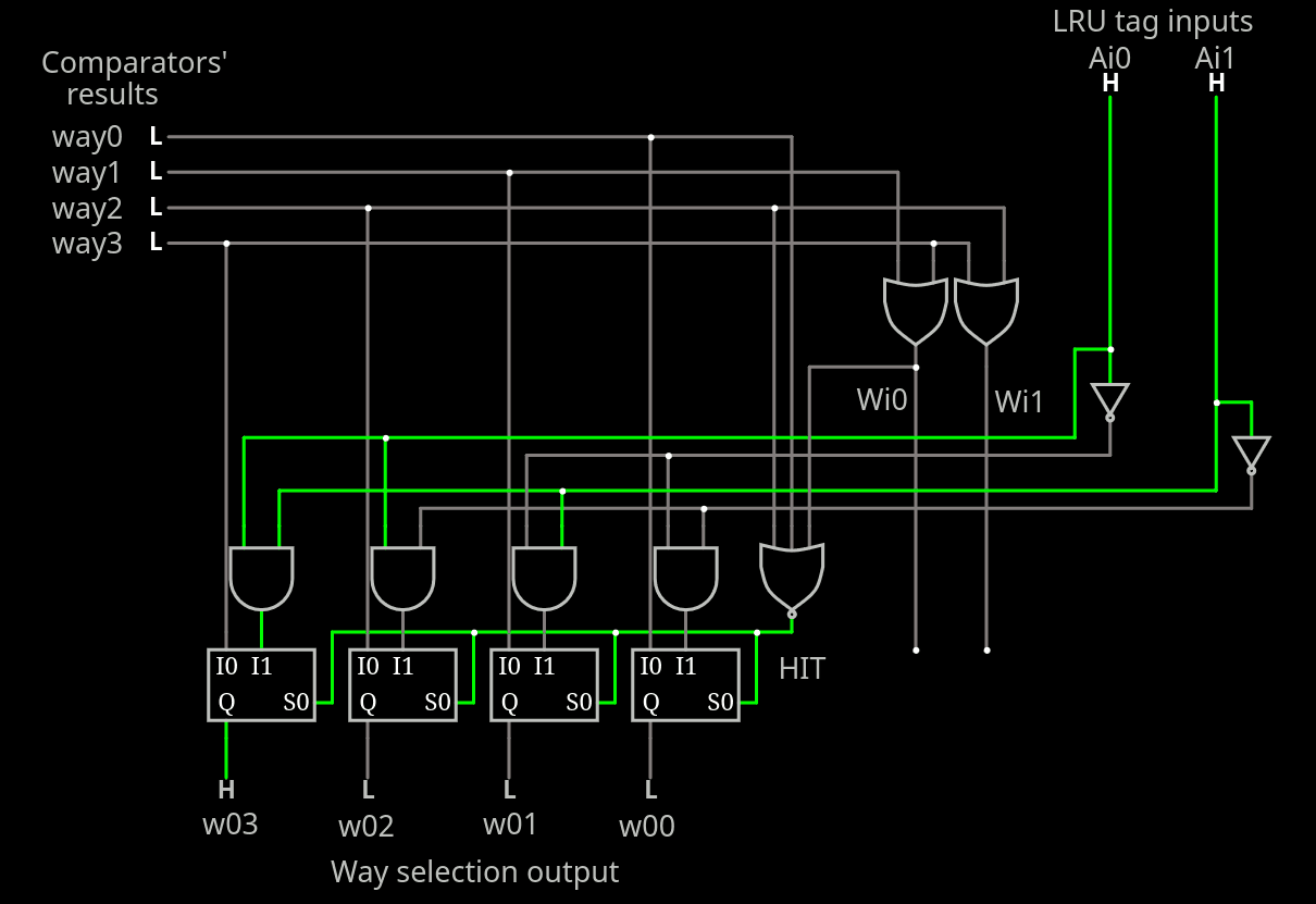
7. Hit or miss
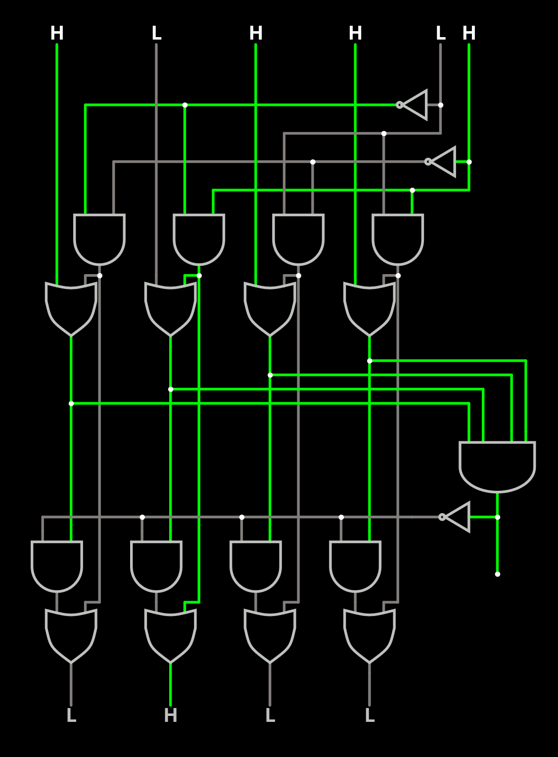
8. More complete myLRU
9. .
10. .
.
.


 zpekic
 Bruce Land
5-way seems easy :
2-way is 1 bit (easy).
3-way (6 permutations) requires 1+2 bits, with the 2-bit field using only 3 codes.
4-way (24) adds another 2-bit field, the new one is fully used.
5-way would require another 3-bit field that is not fully used. But we notice that 3×5=15, which fits in 4 bits. So the 3-bit field and the first 2-bit field can be merged.
So the 5-way full LRU permutations fit in 1+2+4=7 bits, which makes sense since 5!=120=2^7 - 8.
Interesting.
The remaining 8 codes can be used to indicate reset status for example.