 Ian Dunn
Here's how it works:
Clocks were pretty simple when it was just numbers on a dial and a motor turning the hands. it would be a lot simpler to just make an analog clock, but that would be boring! Keeping time with digital logic is pretty complicated, because the clock doesn't start a zero, it starts at 1. Also, the digits stop at 1, 2, or 5. It takes a lot of thought to make the digits count to 59, then advance the next digit while resetting to zero.
Here's how I did it:
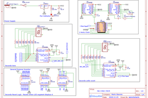
A 32.768khz crystal feeds it's output into a 4060 14 stage binary ripple counter. This divides the crystal's output by two 14 times. It outputs a 2 hz square wave. This 2hz wave is twice as fast as we need, so it's fed to a 4027 flip flop to get a 1HZ signal that goes to the seconds ones counter.
The seconds ones counter counts to ten, then resets to zero and advances the seconds tens. The seconds tens counts to 5 then resets to zero and advances the minutes ones. The minutes count up the same as the seconds, and advance the hours when the count reaches 60. The hours count up from 1, and reset to 1 when the hours reach 13. Resetting to 1 not 0 and counting to 12 is a little tricky. To do this I used an and gate that resets when the hours are 13. To reset to 1 instead of zero I offset the LED's on the hours segment by one. So instead of the one LED being connected to the one output on the 4017, it's connected to zero. Lastly is the CD4082BE dual 4 input AND gate. This AND gate senses when the count has reached 13 or 24 and resets the hours back to zero. But remember, the hours LED's are offset by 1 so when the count is zero, 1 is displayed.
How did you make that cool PCB?
I first heard of flatbed inkjet printers from a Make: magazine article, and after researching them a little more, I found this Hackaday article: "Get your PCB's made at the mall." This was just too cool, and I had to give it a try! So, I purchased a small elephant of a flatbed inkjet printer straight from China. I haven't actually had a chance to try making a PCB with it yet, but it sure does do an incredible job of printing high resolution photos straight onto PCB's. I'm pretty sure the ink is pretty much the same think used at a PCB fab house for silkscreen and solder mask. Instead of being limited to 5 or 6 colors, I can go all the way to the extreme of high resolution graphic pictures straight onto PCB's! Who ever said PCB's aren't an art form?


 Mario Gianota
 Gary Marsh
 SwiftyTheFox001
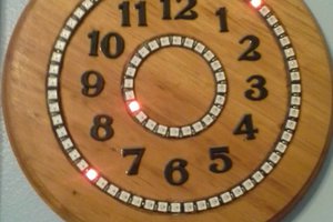
hi all