 Raphael
How It Works
Parasitic Capacitance
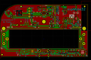
To measure the soil moisture, the board has a parasitic capacitor (really just a pair of PCB traces) that changes its capacitance according to how wet the soil around it is. The ESP32 feeds a square wave to this capacitor through a resistor and we estimate its capacitance by looking at the charge/discharge curve of this tiny circuit. I wrote more details about this cool trick here.
MQTT messages
 While the ESP32 + WiFi are on the energy-hungrier side of battery powered SoCs, on the positive side, we can directly pipe our sensor readings to an MQTT broker. Every so often w-parasite wakes up from its beauty sleep, quickly takes a reading, connects to WiFi, write to a few MQTT topics and goes back to bed.
Powering the Sensor
The board can be powered with rechargeable LiPo/Li-Ion cells. I have experimented with two main types of battery:
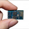
- LIR2450 Li-Ion coin cells. They are super compact (as in the photo above). With around 120mAh, they can only source short peaks of 200mA, which is below what the ESP32 expects. Using them poses a challenge on capacity and current, and that's where the fun is;
- LiPo/Li-Ion cells. They are generally a lot bigger but usually pack up to 3000mAh. They take a lot of space but comfortably powers w-parasite for well over a year;
Battery Life
WiFi and ESP32 are not usually a good choice for ultra low power devices, but since we can get away with long periods of deep sleep, we might just barely get away with it. When active, the ESP32 can consume peaks of over 200mA, and it goes down to around 15uA in deep sleep. The name of the game is trying to keep the active time short - cutting it down from 2 seconds to 1 second essentially doubles our battery life. As of writing, I managed to bring the runtime down to around 400-500ms, but there is still room for improvements.
I put together this spreadsheet as a quick way to estimate battery life. Here are some example scenarios:
- LIR2450 cell (120mAh), transmitting every 30 minutes: around 80-90 days.
- 1200mAh LiPo, transmitting every 10 minutes: over a year;
- 18650 Li-Ion (e.g.: 2700mAh), transmitting every 5 minutes: over a year


 Norbert Fekete
 Davide Raggini
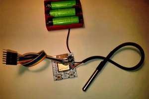
 Guido
Guido
Hello @Raphael . How has your progress been?