-
Add LoRa to the Project for Long Range Transmissions
08/22/2021 at 20:23 • 0 commentsNow lets add LoRa Wan RF radio for Long range Transmission of the data.
Most of the time during my bike rides I do not have any wifi network availible. That#s why I decided to add a LoRa Communication radio to my Bike light.
To enable it we need to add the sensor to TheThingsNetwork
This Network is free of charge and you may check your coverage in your area.
You need coverage of that Network otherwise your data will not be transmitted
First of all you nee to register to the network. You may finde a Step by step tutorial here: Youtube Video:
Once this is done you may find the whole sketch here for scan of WIFI MACs and transmit it over LORA here:
https://github.com/Uspizig/BikeLightLora/tree/main/ArduinoSource/LORA_WIFI_LOCATIONV2
Once this is running you need to setup the backend on Google API.
This is a different chapter...
-
Location Estimation with Wifi Networks
08/22/2021 at 20:08 • 0 commentsHave you ever tought about Using Wifi Location for estimating your GPS Location?
In most of the areas we are typically a Wifi Network is near.
Google offers you a Service to hand over the Wifi Mac Adresses near you and they will tell you where you are.
This API is called Geolocation API
You may find a documentation here. -> Geolocation Google API
There are a bunch of other players in the market that offer the same. E.g. Here Maps, Firefox... and so on.
Just choose the API that is nicest for you.
Once you choosed your API Provider you may SCAN the networks around you.
One the ESP32 combined withe the Arduino IDE this is quite simple.
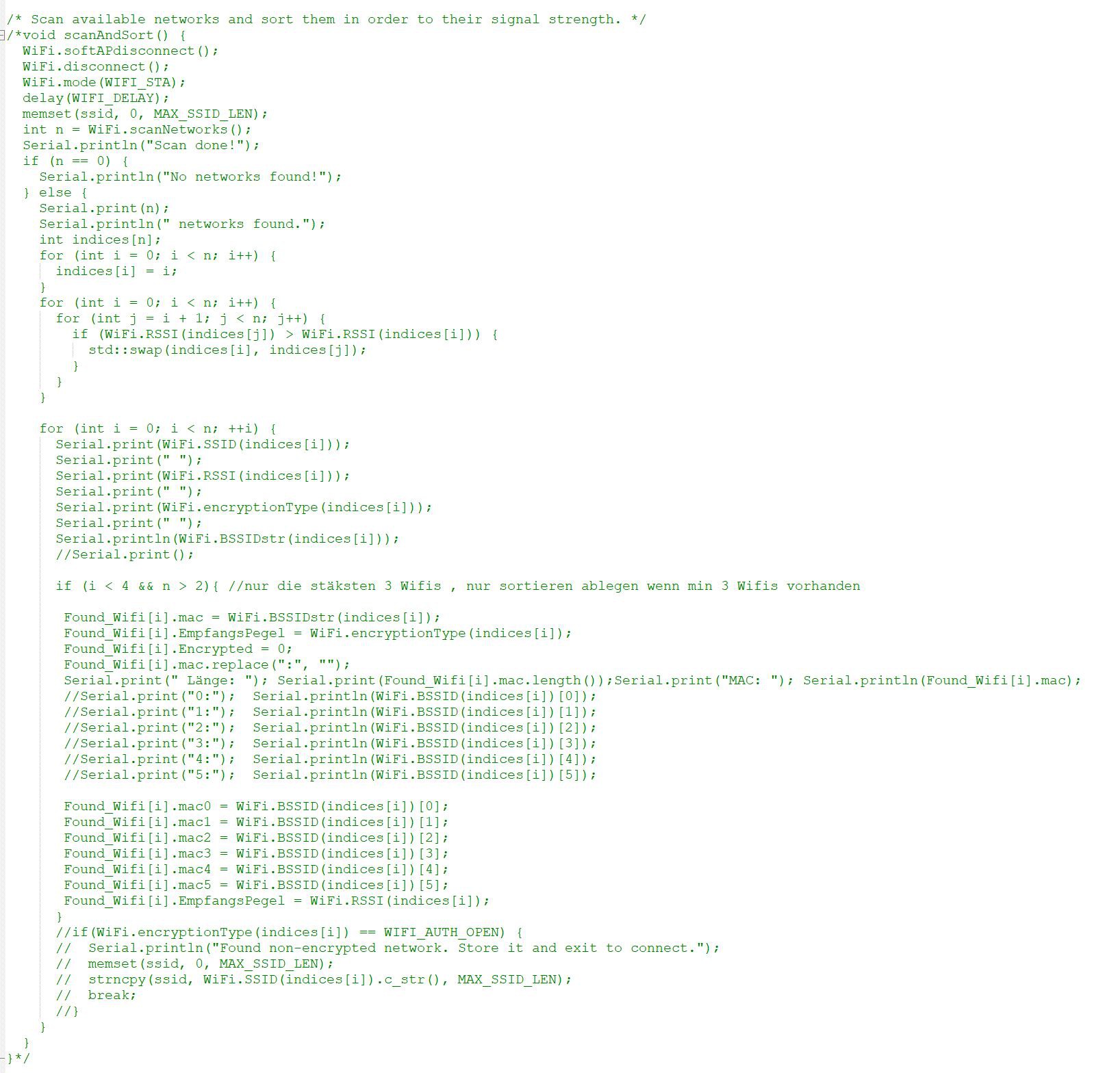
Please see the code below. This code does exactly this. it scans for the nearest Wifi and sort them according to signal strength.
Once this is done the Mac Adress and Signal strength is stored.
Now you can send this Information to a Google sheet.
Inside this Google sheet you can Access the Geolocation API and estimate with this information the location of your Bike Light:
You see in the last Collum of the below sheet. Latitude, longitude and the Accuracy in meters of the Estimation.
For me this is quite scary. All you need to know is three WIFI signals and google knows where you are with a accuracy of 20 meters.
For my privacy I faded my exact MACs and the location.
![]()
-
Fitting the Board inside the old Housing
08/22/2021 at 19:51 • 0 commentsNow lets check if the Board fits inside the old housing.
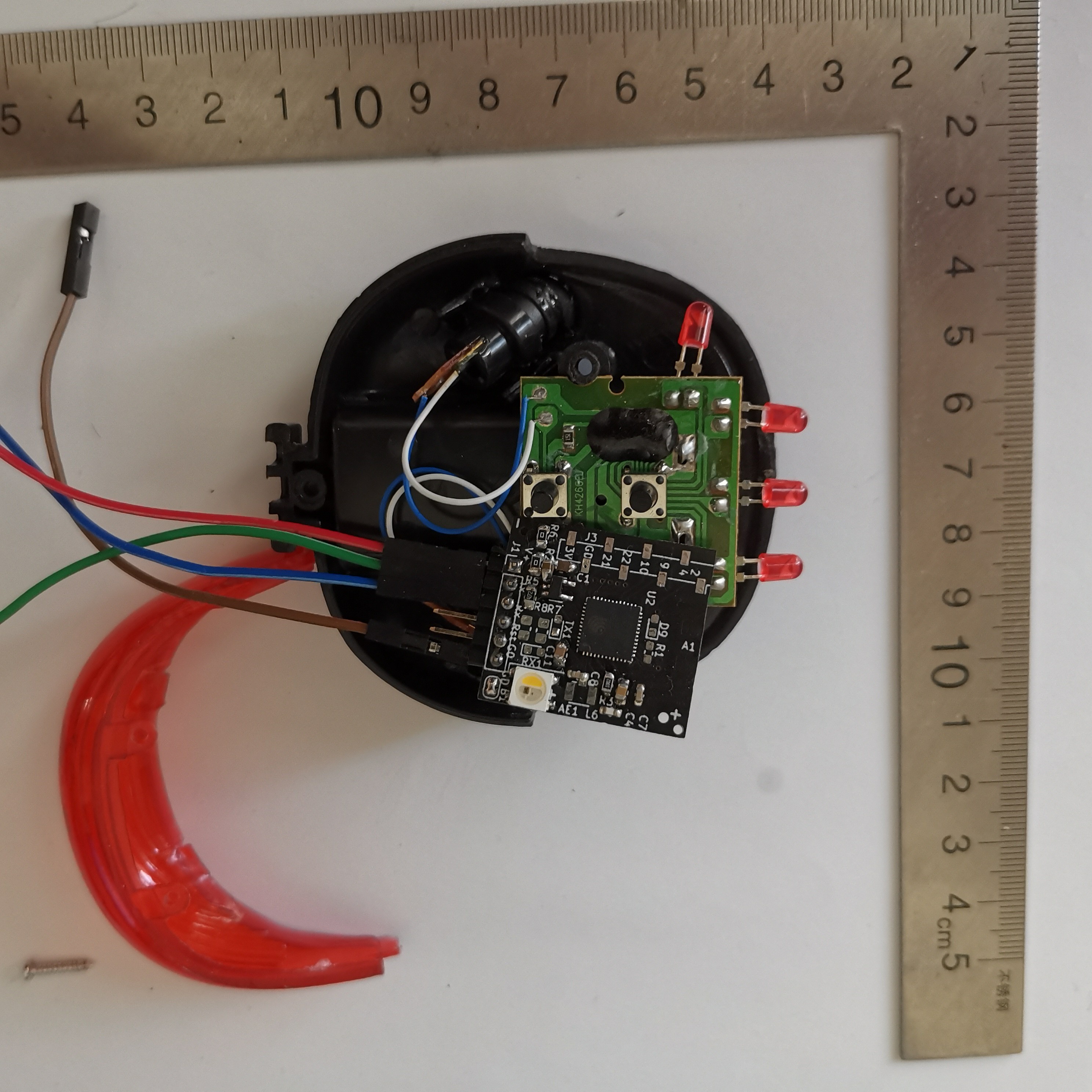
A First Size Comparison looks great.
So we can still use the laser diodes for the image projection.(They work with 3V. Keep the Old battery connector.
But wen need to replace the LED Diodes. The plan is to replace them with a new SK6812 RGB LED.
![]()
-
HW Bring Up - First Light
08/22/2021 at 19:49 • 0 commentsNow comes the SW Part.
For Project Development I use Arduino IDE
For a first test I decided to add a SK6812 LED and led it Blink in different Colors during setup phase
Once this is completed I change The brightness level between 50/255 and 150/255
With this sketch I added OTA Update Capabilities
You may find the source Code here:
https://github.com/Uspizig/BikeLightLora/tree/main/ArduinoSource/firstLightsk6812
-
Boards arrived - HW Bring up
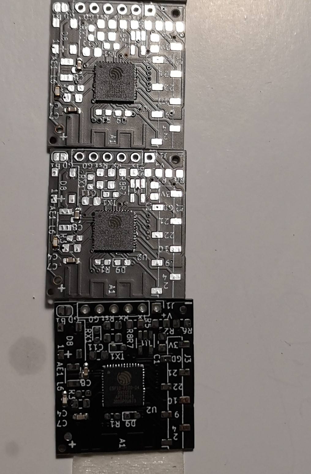
08/22/2021 at 19:35 • 0 commentsAfter 1 week of waiting finally my PCB Boards arrived.
JLCPCB built them nicely and the SMT Soldering looks nice.
In total I ordered 5 pieces.
![]()
So lets add some more components for first flashing:
I added the LDO Voltage regulator and a bunch of 0 Ohm resistors.
For testing purposes I added a SK6812 LED
-
PCB Production issues
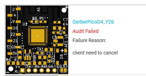
08/22/2021 at 19:03 • 0 commentsAfter I sent out the PCB to production I got mail from JLCPCB
They can not manufactor my board.
The can build it but in the later SMT Soldering process they have issues finding a spot for mounting it to their machines
So I had to cancel my order, and rework my board.
On the new board I had to remove the two mountin holes on the edges. They are now replaced by JLCPB Manfactoring holes.
Lets cross fingers that this works out.
You may find the Reworked PCB as V2 on Github
-
PCB Production
08/22/2021 at 19:00 • 0 commentsNo we need to produce the PCB at a pCB Production site.
PCBs: You may find the Gerber Files here: https://github.com/Uspizig/BikeLightLora
Download the GerberZipFiles (V1 or V2) from Github. V2 is optimized for Automatic Placement of parts
Upload these Files to JLCPCB, -> Instructions how to to this can be found e.g.: Here
Choose the color of the PCB and the Material: You may try out new Aluminium PCB for better heat dissipation
Now add SMT production
Upload the two Files you may find in the Folder Place. Here Placing and Orientation of the parts
I by myself only choosed to solder the ESP32 and the Capacitor C7, C8 & Inductor L6 for the Antenna.
All the other components I had in Stock on my desk.
Sent your Order to process and do the payment.
Order your parts for this Project:
You may order your parts at LCSC, Aliexpress or your local electronic parts distributor.
-
3D View of the Board
08/22/2021 at 18:47 • 0 commentsKicad gives you the chance to watch your finished design in a 3D Viewer
This helps me a lot to see issues on the Board before they go to production.
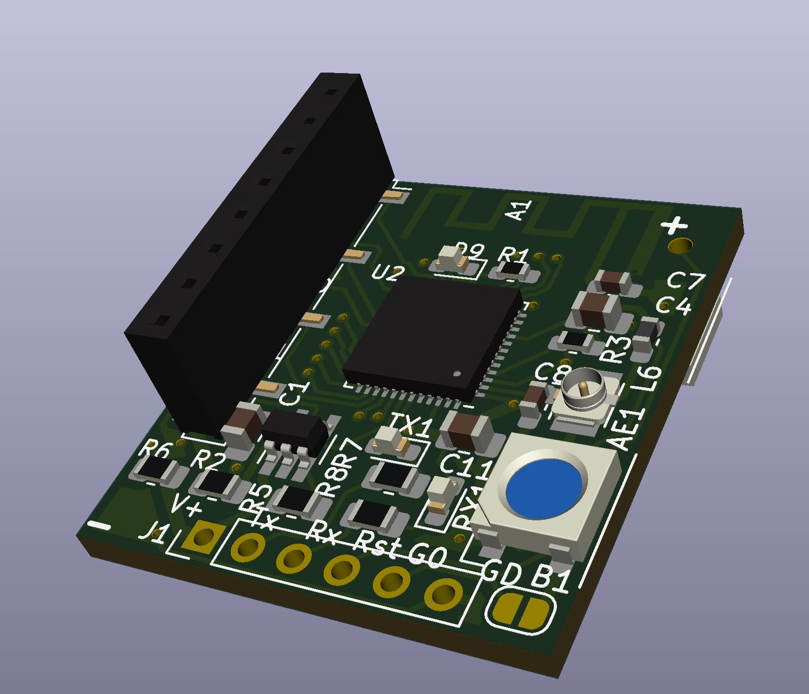
Top Layer of the board:
You might see here that some Labels on the Silk Layer are not that nice and are overlapping. With the 3D viewer in Kicad you may detect this and correct this before you produce your board.
I added in the final design as well a connector for an external Wifi/BLE Antenna. This was done if the Onboard PCB Antenna does not perform that well.
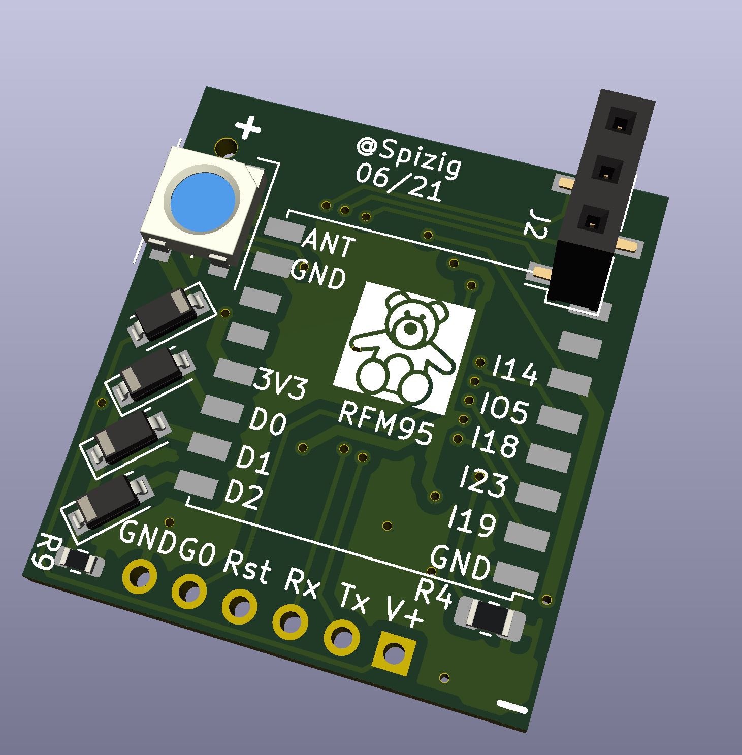
Bottom Side of the Board:
On this side the LoRA WAn Module will be added later on.
You see there as well the Connector J2 is overlapping with the RFM95 outline. I did this on purpose. In my application i will not connect the J2 connector that likely. So i did not care about the violation.
-
Layout a PCB
08/22/2021 at 18:40 • 0 commentsLets bring this schematic to a PCB Design.
I started doing PCB Designs in University. Back in the time I was using Eagle or Altium.
In the last couple of years the Open Source tools have become better and better.
Thats why I choosed KiCad for my hobby projects.
Once finished with the schematic you need to start a new PCB Design with the Tool PCBNEW
This opes a drawings program where you can add all you components.
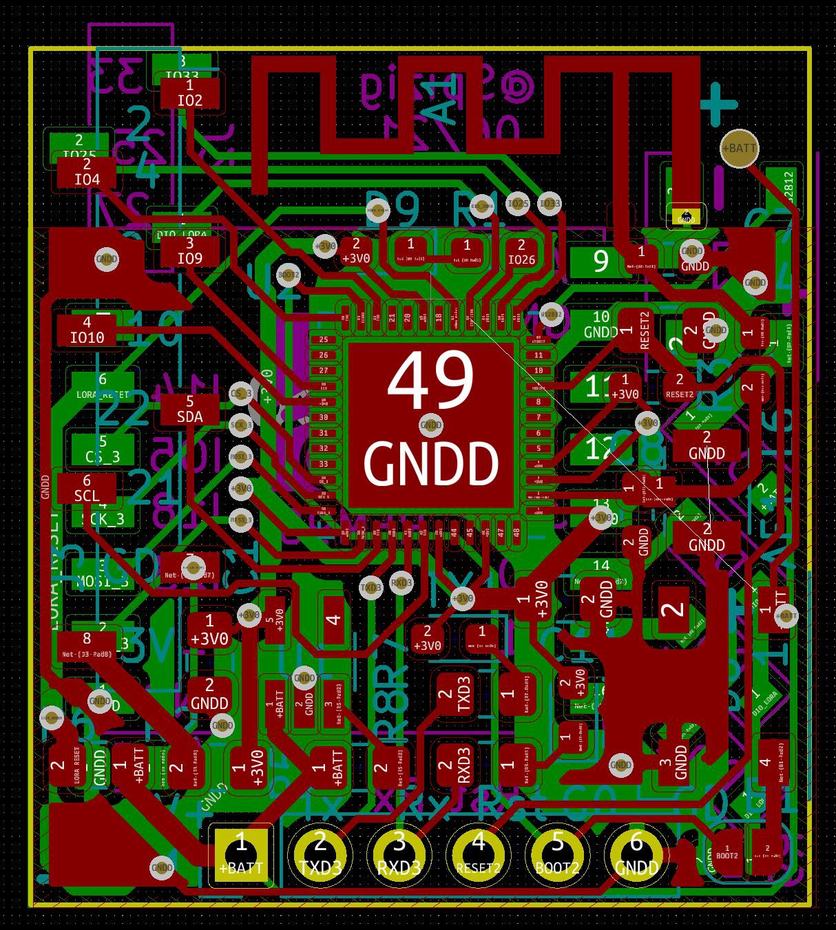
No the fun part begins.Place all your components so that you can still solder them and you may route the signal lines.
At the end. Add a Ground plane and think about thermal and EMC.
You may see that there is one line on the bottom side of the Board which is not routed. I did this on purpose. This line is not needed all the time and i can add this line later on with an Air wire if needed.
-
Schematics Considerations
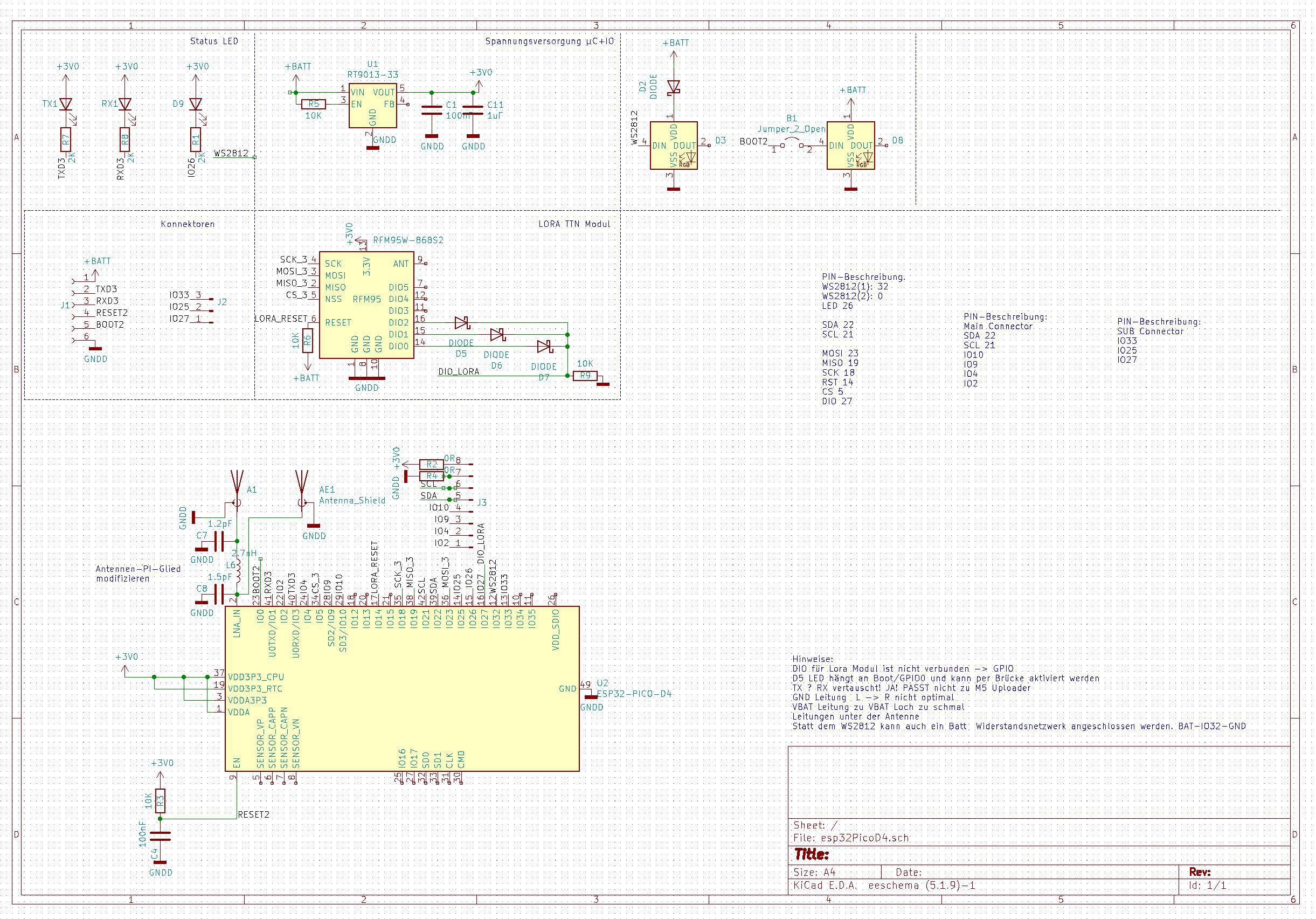
08/22/2021 at 18:33 • 0 commentsThe idea for the schematics was to stay as small as possible. Thats why I only choosed to have a bare miniumum of components on the logic board.
At the current project situation I could not decide between a different bunch of sensors.
That the reason why I added a connector to replace Sensors on the fly.
Choosing the components:
Power Supply:
a Low Drop out Voltage Regulator: I choosed the RT9013 It can drive up to 500mA on the 3.3 V Output and you can supply it with a maximum Power input of 6V. Perfect for USB or Lipo Power Supply
LORA Module:
The RFM95 is a prebuild LORA WAN 868 MHz Module that can establish a Longe Range LORA connection.
You can achieve up to 15km of range with this Radio chip. That is really crazy. We are gonna use this later on for location detection.
In my Area Stuttgart Germeny we have a public Lora Thethingsnetwork sponsored by the City Council. This gives me the opportunity to use this network for free.
The LEDS - SK6812 WW
You may have guessed it: But you are Wrong: No I am not using WS2812B RGB LEDS.
The reason is there is a nice competitor on the market. Called SK6812WW: You have the same footprint but a seperate White channel. This might be useful for a torch Light Function later on.
I choosed two different light paths. So you can have a status light and a seperate Backlight on one Logic Board
A 8 Pin 2.54mm Connector.
This connector is useful for all kind of sensors. There are lots of sensors out there in the market that fit on these connectors.
I made 2 0Ohm Resistors on Pin1 and Pin2 so you can easily switch orientation of 3.3V and GND. Some Boards differ on
A 3 Pin Connector with Special pins
I routed a three Pin Connector with some special pins extra on a connector. Watch espcialy Pin 25. This is connector to the DAC of The EP32 board. This gives you the chance to output some audio. This might be useful if you want to playback some sound
A Flash Soldering Connector
I am using on all my projects a USB to UART Programmer from M5 Stack. This tool is easy an so convieient
LoRa Bike Light with Indoor Location Estimation
A makeover of a Bike rear light that scans the WiFi Networks in your surroundings, and transmits the Data via LORA
 Ulrich