 kelvinA
-
[A - T] Branding and potentially shelving
05/28/2022 at 16:29 • 0 comments![]() So, after compiling all the research I've gathered over the past few days, my compute returns a low probability that I'd get more than even get a denominator-double-digit fraction of this project complete in the time I'd want it delivered. It seems more to be a kind of project that is worked on at a slow but consistent pace, since there is so much stuff that would have to be learnt.
So, after compiling all the research I've gathered over the past few days, my compute returns a low probability that I'd get more than even get a denominator-double-digit fraction of this project complete in the time I'd want it delivered. It seems more to be a kind of project that is worked on at a slow but consistent pace, since there is so much stuff that would have to be learnt. Obviously, shelved != scrapped; it's more like "frozen". I'll still be keeping my eyes on anything that could push this project forward though.
I thought I should at least add some branding, and the square project image wasn't as great as I imagined.
![]() And now I'm staring at "Sketch" and it looks kind of... prickly? Coarse, maybe? Additionally, CAD Sketcher now exists. enLoften might be my backup name as it sounds calmer and more refined, even though I don't usually use the loft tool all that much. Perhaps that could be a reason to look into making the Loft tool easier to set up than in current CAD packages.
And now I'm staring at "Sketch" and it looks kind of... prickly? Coarse, maybe? Additionally, CAD Sketcher now exists. enLoften might be my backup name as it sounds calmer and more refined, even though I don't usually use the loft tool all that much. Perhaps that could be a reason to look into making the Loft tool easier to set up than in current CAD packages. -
[R] Geometric Modelling Kernel
05/27/2022 at 10:55 • 0 commentsFrom what I can understand, the Geometric Modelling Kernel, commonly shortened to the CAD Kernel, is the part of software actually responsible for creating the mathematical representation of the part. In FreeCAD, I heard a few problems were attributed to OCCT, and Fornjot seemed to be making their own, so I set out to research further into potential kernels over the past 3 days.
- Open Cascade is the most fully featured, it seems
- BRL-CAD Kernel can't do fillets apparently
-
[T] Starting to plan a concept workflow
05/24/2022 at 13:29 • 0 commentsPublished: 15:34, Tues 24th May
Yesterday, I saw these two videos:
I thought it was intriguing and recreated it in Fusion360, and then thought about how I would do it in enSketchen only with the hardest device being targetted: the full-Android smartwatch. These watches are on China for between £30 and £160 depending on features and popularity, and I've used them as my main cellular Android device for years. I still much prefer square/rectangular ones to circular ones as I can get more done on them, but I'll explore to see if an interface can be made for both.
Designing for a smartwatch screen both helps to highlight how many clicks somebody on a PC or phone might need to take to produce a part, as well as having a workable user interface for split screen on phone and a really small window on PC.
Smartwatch
The idea is to have 4 digital buttons in the corners for an experience similar to Casio digital watches. These buttons can be held to activate a second function. Using draw.io, this is what I've got so far:
![]()
- We start by clicking "new document".
- The user's start template is loaded in. In this case, it's creating a Sketch Node with the initial Plane Node set to XZ and a Project Node follows afterwards that projects [ 0, 0, 0].
- The user can easily select "XZ" to open up a dropdown that shows the other 2 plane options.
- All nodes are placed in like a "master grid" to keep everything automatically tidy and easily navigatable.
- At this moment, the user is in a sketch and the 4 side buttons are to exit the Sketch Node, add geometry (like lines and circles), go to a view mode where the user can see the current status of the sketch and add a constraint, all in their respective positions.
- If you press and hold, the grey text part of the table applies.
- I'll probably set Other Page to the top left and have "Exit Node" be a press+hold, because the user needs to be able to do other things like create another plane in the sketch node.
- "Other Page" loops though all the pages, similar to a digital watch.
- The user then clicks to go into the construction geometry menu and then a circle, which places a Circle Node after the Project Node. Defaults are a 1mm diameter circle at the centre of the user's view. Since they haven't moved around in the sketch view yet, this center is [0, 0].
- The user then clicks the "Center Point" input, "Add Constraint" and "Coincident". A list of valid things to coincident are sorted in a list by how close they are, meaning that if the user doesn't see it/know which object they want, they can exit the menu and move the object closer and then come back to see if its higher up on the list.
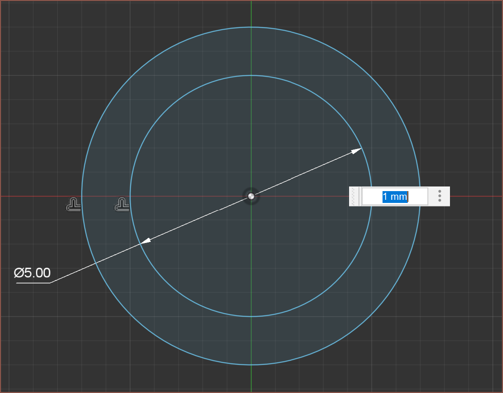
- So now there's a coincident node added and then the user clicks the "Diameter" input, hold for maybe 0.5s and then can slide their finger left and right to increase or decrease the value. At the same time, the circle is visible with a sketch grid (sparcely numbered) so that the user gets visual feedback on how big or small the circle is.
Normal Lines
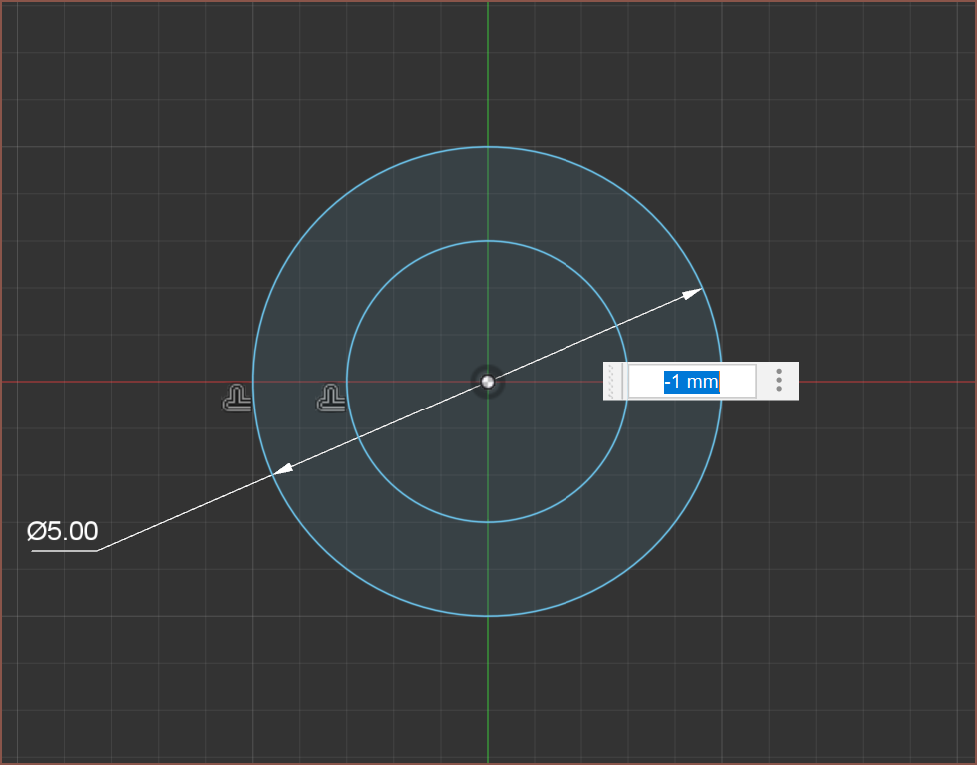
Additionally, like planes, I would like lines to have a normal line, meaning that dimensions are usually signed. Think of it similar to dimensioning an offset in Fusion 360 where a positive dimension is one side and a negative dimension is the other side. The behaviour can be changed on a per line basis. I want to implement this feature in hopes of getting a fully constrained, no other solutions sketch.
I'm sure users of Fusion 360 have experienced when a dimension, line or arc has swapped sides. There are many cases were a fully constrained sketch could still have 2 or 3 solutions depending on location of the sketch elements.
This approach also allows to do the following:
- Imagine 2 concentric circles of different sizes.
- Now if you click on the circumference of the larger of the two, and then the smaller, create a dimension.
- Enter 1mm as the dimension.
- The smaller of the 2 will now have a diameter that is 2mm larger than what was previously the larger circle. The first circle selected would not have changed size
- This is because I have defined negative dimensions as inside circles and positive dimensions as outside.
- In Fusion360, you would have to first drag the smaller circle until it was larger than the largest one before dimensioning it.
Some images of the Fusion 360 Offset tool, which may help convey my idea:
![]()
![]() For arcs, perhaps the software would ask if you want a 180 degree or a 0 degree tangent.
For arcs, perhaps the software would ask if you want a 180 degree or a 0 degree tangent.Conclusion
I'm coming up with a bunch of workflow pathways faster than I can add them into the flowchart, so I'm likely going to be doing more over the coming days to explore the UX and workflow. If I can get some half decent speed on a smartwatch, all other platforms should feel resistanceless.
-
[T] Project and feature plans
05/23/2022 at 18:31 • 0 commentsSo I'm looking around other projects [see Research Links at bottom], and if I'm actually going to write this software, I want to go from 0 to over the "basic modelling software ceiling" in features as fast as possible. Features that most all CAD software, big and small, would be able to do. Think things like doing a difference (Combine Cut for those who use Fusion 360) between a cube as the main body and a sphere as the cutting tool. If the project doesn't get further than this hypothetical ceiling and ends up being abandoned, there's almost no return on investment for me since I could've used those features from day 0.
What I need to focus on are all the features that would allow me to actually port over my Fusion 360 designs. With the perspective of looking at the project as if it wasn't mine, I'm currently writing a list of features sorted and rated from 1 - 5, 1 being "That's a nice to have feature that exists/doesn't exist in Fusion" and "Dead on arrival. What other options are out there?". A 1 feature would be some node based workflow for NURBS (The Fusion 360 workflow isn't history based so I never really used it) wheras a 5 would be the ability to use components. 2 and above are features I've actually used or wanted, like a history based Move Faces command.
Research Links
-
[R] Nodi, and other research
05/22/2022 at 15:15 • 0 commentsSo development on #SecSavr [gd0036] has, once again, been stalled while I look around to see if there are options outside of Fusion 360.
Initial Search
My initial search lead me to https://wiki.freecadweb.org/Node_editors, where I looked though each of them to see current statuses.
The developer(s?) of the most recent node-based workflow in Freecad are wondering if they should switch from PyFlow as it's no longer maintained. Another project to bring PyFlow to FreeCAD is this: https://github.com/microelly2/NodeEditor. A currently maintained node project for Python is Ryven.
Sverchok looks like it's mainly for Blender. Modelica seems to be for simulation.
I'm slowly getting through the forum threads for DynFreeCAD and Pure-Data, but Pure-Data is looking promising so far.
Nodi
Tabbed back from the FreeCAD path to Google again to continue the search. Searched "node based cad github" and that's when I discovered https://github.com/Nodi3d/nodi.
![]() It's got a peaceful looking interface and a 3D viewer that doesn't need a key held down to zoom, pan and rotate.
It's got a peaceful looking interface and a 3D viewer that doesn't need a key held down to zoom, pan and rotate. ![]() Examples are provided and each node also has a link to discover more.
Examples are provided and each node also has a link to discover more. Some things I thought when using the software:
- Being able to view compute time is useful.
- While I like that shadows don't go pure black when the angle from the light source is almost 90 degrees, pure white on the top face isn't ideal either.
- Some kind of "Pause Compute" and "Compute to here" feature should exist for changing parameters or trying to figure out what does what in a model.
- As expected, all the nodes and wires look like a mess
- I'm thinking of having a wireless wire feature, as well as an auto align for node blocks.
- Being able to use this file as a component node for other files would be a desired feature.
- In enSketchen, I'm thinking of an "expose" node that connects the inputs or outputs of the node tree to its enclosed node, like an API. For example, an "Input Expose" for "width" in the file "box" would show an input node dot with "width" for the node corresponding to the file "box" when used in another file. This will allow parameters to be fed through to different files, as well as make more library friendly files like bolts.
This is still very early research though. I'm currently reading the nodi docs.
[Published 16:39]
-
[R - E1] Node-based CAD
05/20/2022 at 08:00 • 0 commentsYesterday night,
before I went to bed, I thought:
- Direct modelling makes it easy to adjust some things and hard to adjust others (that would depend on some sort of history).
- Code modelling makes non-fragile models but 2D sketching would get complex quickly.
- Fusion 360's top down approach is nice, but being limited to 1 timeline means that components that aren't dependent on each other still have to be modelled one after the other.
and so I thought "what about node based CAD?"
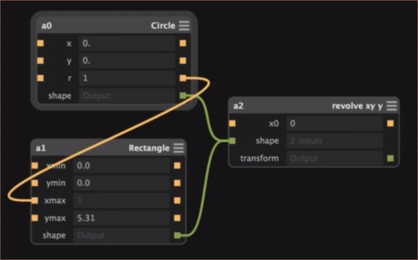
The first Google result was very promising: https://lesterbanks.com/2015/06/antimony-a-free-node-based-3d-cad-modeling-tool/
![]() I was never a fan of the spline lines though. For me, it just makes the nodes look tangled. I'm thinking of a metro map or PCB layout UI that makes the whole thing look neater and less "spaghetti node".
I was never a fan of the spline lines though. For me, it just makes the nodes look tangled. I'm thinking of a metro map or PCB layout UI that makes the whole thing look neater and less "spaghetti node".Anyway, I posted the link in the 3D Printing Discord and the next day, I also got Elephant (MoI3D), Grasshopper (Rhino) and Dynamo as suggestions.
![]()
Click image to see original video Dynamo looks very close to the idea I was thinking of last night, where you have multiple "timelines" and you can see the model behind them all. I was also thinking of having the option of a vertical timeline. I also want some sort of feature sync feature (or an easy workflow to keep them synchronised) with another similar part.
Example Workflow
The axis sliders from gd0036 will be the first workflow I'll try and make into a node based timeline from, as they are derived from very similar parts that only differ in the diameter of the tube very early in the model.
![]() I think the most straigtforward approach is to have a sketch node that goes into a node that makes a tweak to one of the parameters and outputs that new sketch. In this case:
I think the most straigtforward approach is to have a sketch node that goes into a node that makes a tweak to one of the parameters and outputs that new sketch. In this case:![]() where:
where:- All nodes have their own subsystem of nodes.
- "Adjust Parameters" adjusts the parameters used in the input sketch.
- Nodes with chain icons try to sync their features together.
- The main problem for extrudes is when the amount of available profiles change and how to go about understanding the design intent or getting it from the user without asking too many questions.
- A similar problem could crop up for sketches. I'm thinking that there should be something similar to CADquery selections when choosing what lines and faces are projected to the sketch, and make that a node so that you don't have to touch it if the software deduces correctly, and can make tweaks if needed.
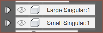
- Coloured text are timeline string variables created on the fly.
- so I can start typing "sing" and enSketchen gives me the option of making it just text, making it a timeline variable or selecting the variable "Singular". This should be sorted by highest probability.
- This is so that if a user decides on a new name for a part or sketch, all the subsequent feature names can be automatically changed.
- There might need to be a timeline freeze button, so that a user can work on, fix and/or sort out the features for one part and then sync changes with other timelines.
Performance
Multiple timelines should also make multithreaded computes more viable. Ideally, I would also like to use an implicit CAD approach for further performance gains. I'm also thinking of an "Expose" node, where it makes a... actually it's more like an "Export" node, where a seperate enSketchen file is created that is synced to the node timeline. This is so that parts can be imported into other components without having to import everything from the previous file, potentially improving performance. "Export" could also have subnodes, so that it's possible to do things like reorientate a part before auto exporting it, which will be useful for projects that have a lot of parts that need to be printed.
Sketches
Nodes in sketches will make 2D sketching more parametric than they are currently. For example, scripts could be moved around in the order when they are executed, and parameters can be piped to them. Maybe a "solve for" input might be needed, so that a solution can be found to fufill a constraint instead of having a parameter. Another example are sketch fillets and chamfers. I think it would be nice to have sketch fillets that work like their 3D counterpart in Fusion 360.
Each sketch node will have a menu where all its related constraints are. I think that's better than a large list of contraints and trying to select that one contstraint nested under 5 other coincidents. Ideally, I'd also like to have some sort of "construction selection", for those times when I only want parts of a circle or rectange as construction but I don't want to break the lines and turn them into arcs or lines with coincidents dotted about.
The sub-node of a sketch will start with a plane node. This should have a "flip" toggle so that the plane can be facing the intended way. The plane would act like a planar constraint to everything that's connected to it. It's a node, meaning that more than one plane can be in a sketch. This is useful for features like loft and sweep that usually require multiple sketches in current CAD software to generate. It also means that sketches are intended to be 3D compatible. Helixes come to mind.
Icons and Fonts
I also want to see what can be done to make parametric icons and fonts with this method. Watching through a few FreeCAD iconpack creation efforts, it does seem like icon lines and colours could be parameterized to speed up icon creation, and allow for tweaks and changes such as line widths or fillet radii.
[Published at 10:13]
[14:45]
Related Videos
The above is a video I found just now, which shows that nodes can be used for precision or organic shapes.
I saw this video a while ago but didn't make the connection. Well, this was before even thinking of this project so there was no connection to make.
-
[A] Subproject for gd0045 CAD functionality
05/20/2022 at 07:21 • 0 comments[Tag A = Announcement]
As such a feature is large, I'm thinking that it might be beneficial to make this a Researching Project again and have logs in gd0045 be more CAD focused.
Old project details:
The way I model is through sketches and usually not through booleans. This is a research project to see if a timelined 2D sketch environment is feasible. Cadquery seems promising.
Worst case scenario: I have to make new CAD software. Slightly better scenario: I have to port over something like FreeCAD to a functional language like F#.
-
Shelving this project
04/10/2022 at 15:19 • 0 commentsI'm shelving this project as it is being merged in with gd0045.
-
[R] ImplicitCAD
03/05/2022 at 10:22 • 0 comments[R] = Research log. I'm expecting most of these to be unnammed.
I found an implicit, code based 3D modeller: https://implicitcad.org/docs/api
It unfortunately seems very limited at the moment, but I do like all the things that can be done with linear_extrude.
-
Functional Languages
03/01/2022 at 19:30 • 0 commentsSo I looked for languages better than C#, and I actually found a comprehensive review list and I discovered the benefits of functional languages. Looking through the syntax of F# made me more eager to program than I have been for a while, especially with the prospect of using Microsofts new MAUI with it. However, Higher Kinded Types are unfortunately not a feature, which essentially is being able to write parameterized code (you only need to write general code for multiple types instead of copy-pasting for every type you want to target). It's been asked in the F# and C# communities for years, so it seems that feature will never get into production.
This entire project started because Fusion 360 brought out a new feature that allowed driven dimensions to be given a parameter, but they only worked in the same sketch. Autodesk said that an updated version would come Soon(tm), but that could be months, years
So I went on a tangent, looking at other FP languages such as Haskell, but after quickly researching alternative languages to C for embedded systems and finding none, I asked myself "Can I use any of these other languages to write an app for both Windows and Android?"
- Couldn't find any frameworks for JVM targetting languages, like Scala or Eta
- PureScript compiles to JS, but suprisingly there's no JS frameworks for the task either
- JS -> Mobile exists, JS -> Desktop exists, JS -> Mobile and desktop does not
- I don't think Flutter can use JS code either
- Haskell doesn't seem to have anything much for application development
I feel like I read somewhere that F* (different from F#) had Higher Kinded Types, but I dismissed it as their website looked too old to still be in active development. However, I've just found https://github.com/FStarLang/FStar with a commit an hour ago, so obviously it's still alive, so I'll update the entry if I find something interesting.
Other than that, the nice and compact (but readable) syntax of F# already got my foot in the door, and many regard it as a great language that has less bugs post-compile to worry about, so I'll move forward with this language.
enSweepen [gd0096]
Procedural and parametric, node-based CAD for 3D modelling with sketches.
 So, after compiling all the research I've gathered over the past few days, my compute returns a low probability that I'd get more than even get a denominator-double-digit fraction of this project complete in the time I'd want it delivered. It seems more to be a kind of project that is worked on at a slow but consistent pace, since there is so much stuff that would have to be learnt.
  And now I'm staring at "Sketch" and it looks kind of... prickly? Coarse, maybe? Additionally, CAD Sketcher now exists. enLoften might be my backup name as it sounds calmer and more refined, even though I don't usually use the loft tool all that much. Perhaps that could be a reason to look into making the Loft tool easier to set up than in current CAD packages.
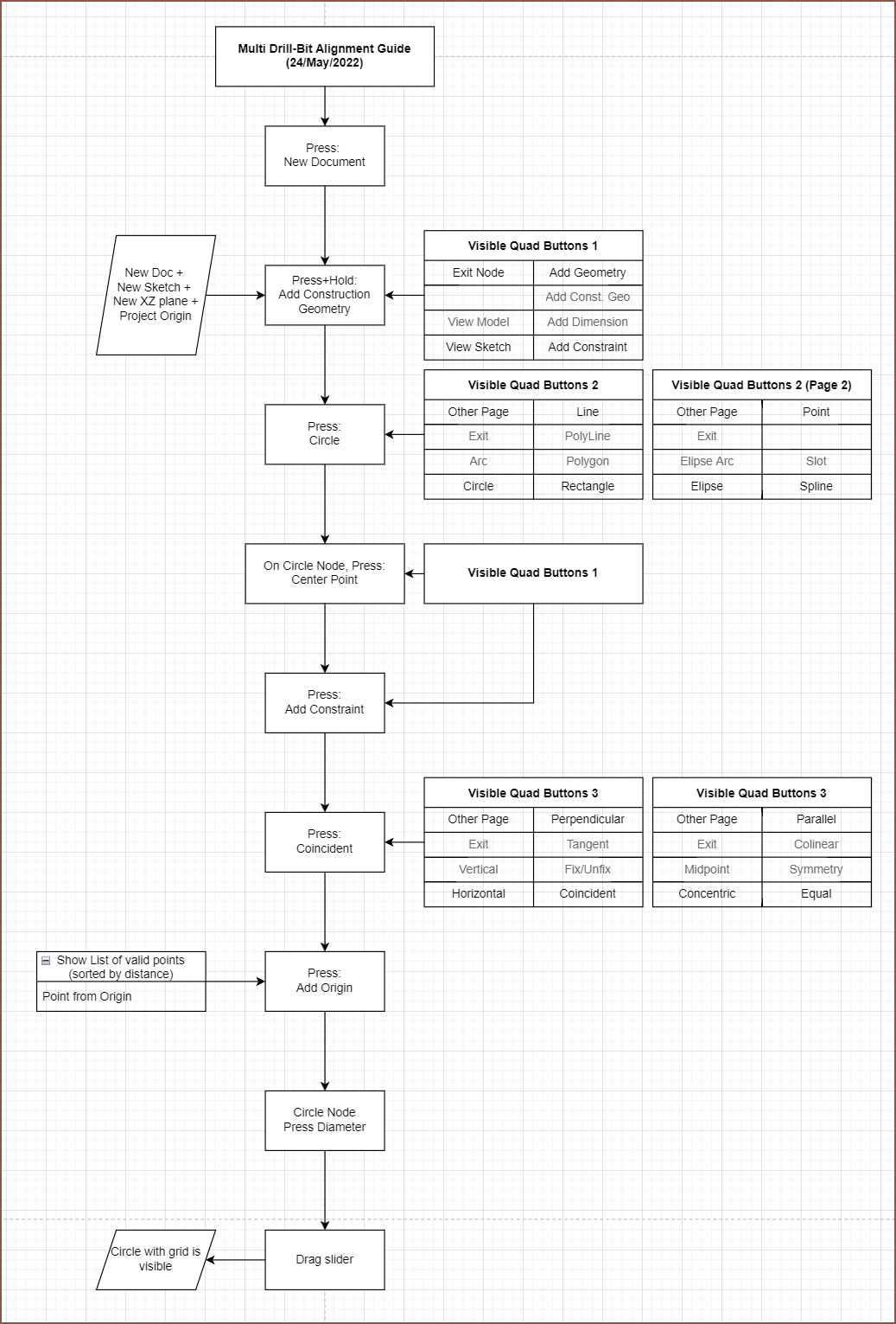
 For arcs, perhaps the software would ask if you want a 180 degree or a 0 degree tangent.
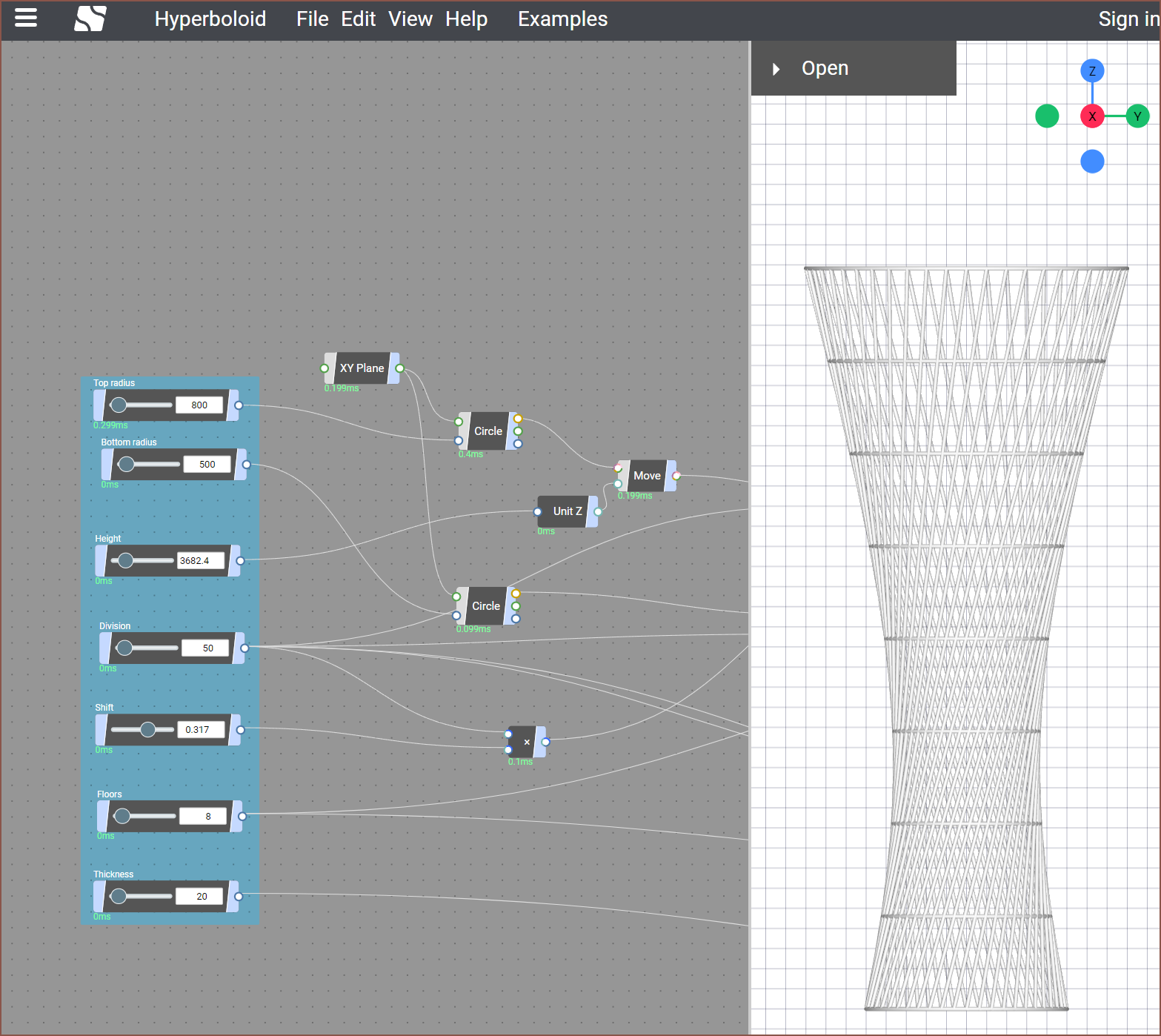 It's got a peaceful looking interface and a 3D viewer that doesn't need a key held down to zoom, pan and rotate.
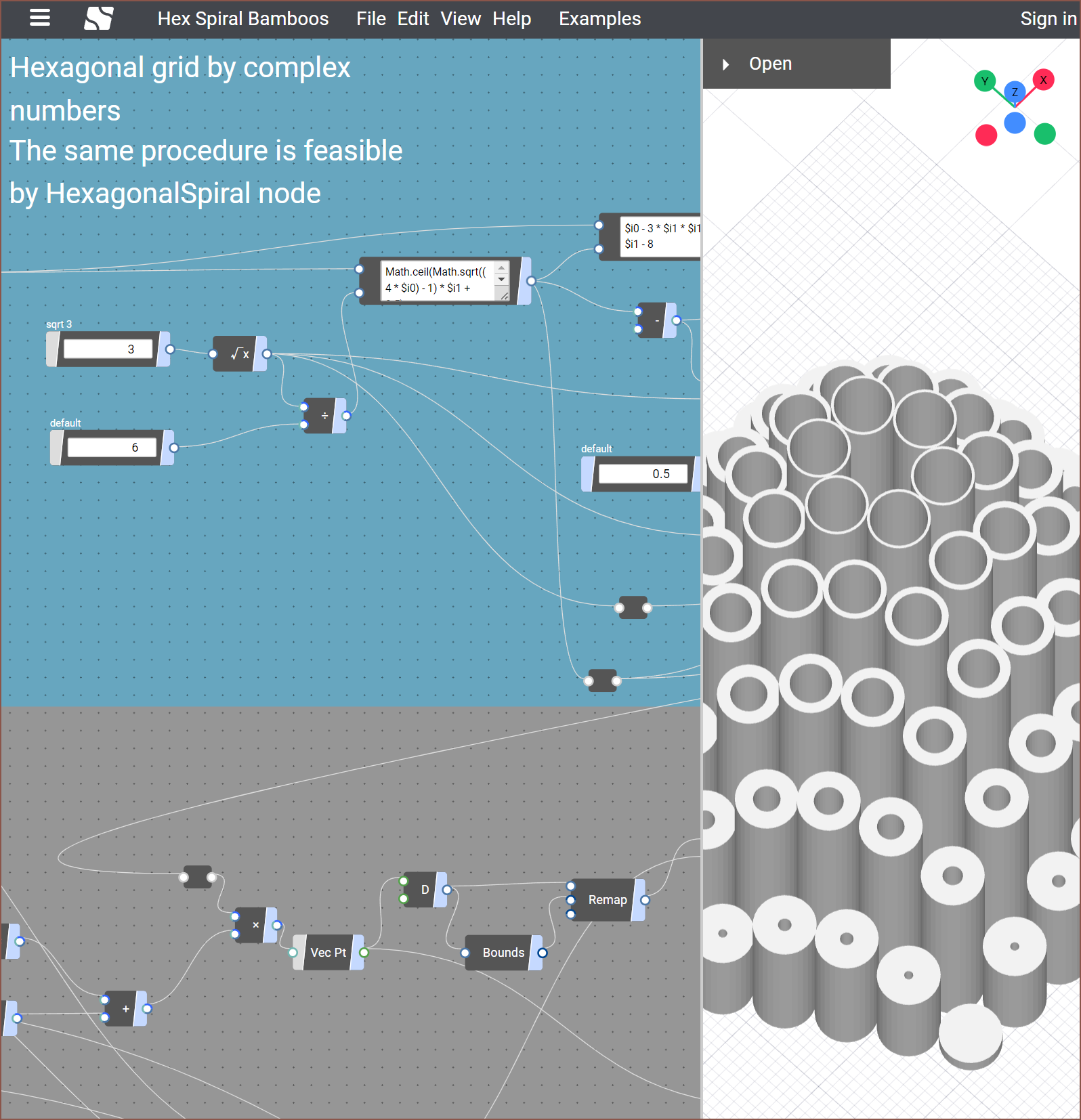
 I was never a fan of the spline lines though. For me, it just makes the nodes look tangled. I'm thinking of a metro map or PCB layout UI that makes the whole thing look neater and less "spaghetti node".
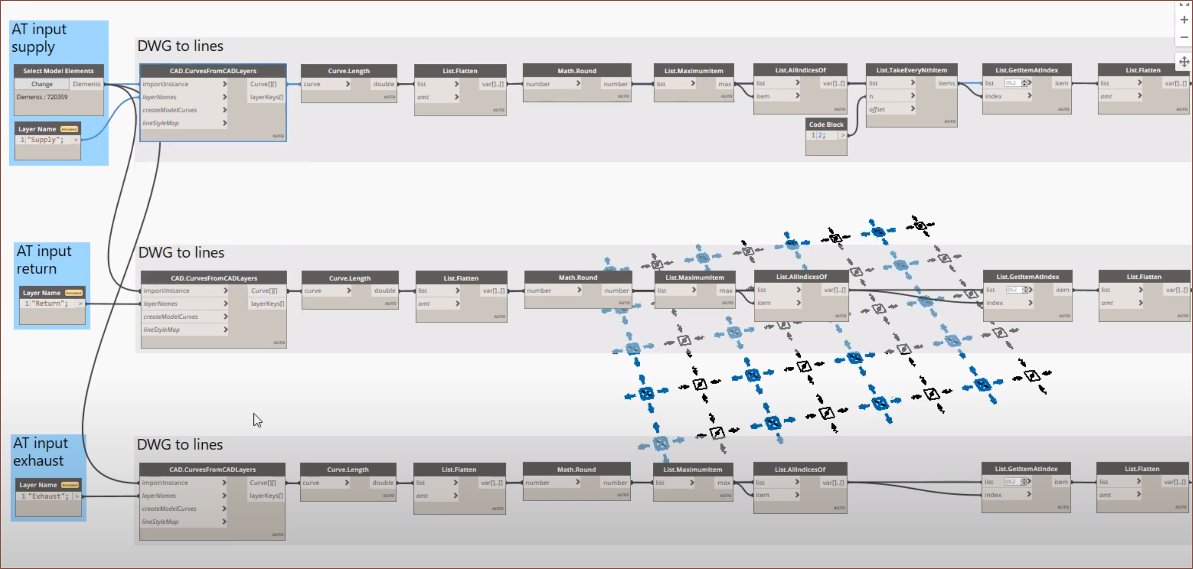
 I think the most straigtforward approach is to have a sketch node that goes into a node that makes a tweak to one of the parameters and outputs that new sketch. In this case:
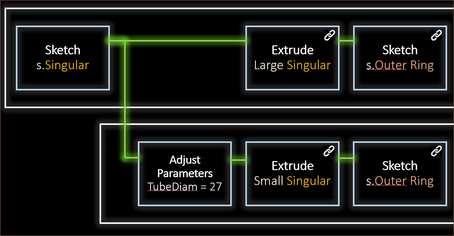 where: