ElectroBoy
We made many amplifiers supporting stereo channel, mono channel, single/bridge mode. And today we are here to set up a high-power mono channel audio amplifier system for our bass tube. My bass tube has 8-inch subwoofer which handle up to 200watts. But I always recommend to utilize 70% of this, but in this 100–120-watt amplifier is enough.
We need a low pass filter so that it only passes low frequency signal. Which are the requirements for a woofer inside bass tube. Every woofer has different resonating frequency for the best output. But using this circuit we are using frequency of 10Hz to 200Hz. Which is ought to be good response for my bass tube.
You need a separate system to get the sound, because this amplifier only produce bass. In a car you can use one audio channel to drive inbuilt car speakers for sound other one for the bass output through amplifier.
Designing:

Then we will Design a PCB layout to fulfil the need of circuit. I want to make this amplifier as small as possible which can be done by making a 2-layer PCB. I always use JLCPCB for my audio circuits because it reduces the efforts and easy to assemble and solder.
Amplifier IC:
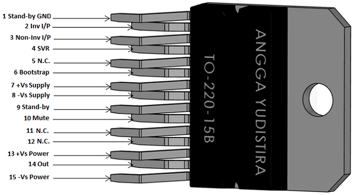
We need a high-power amplifier IC, here I am using TDA7294 which a 100w class AB audio amplifier. TDA series is known for its Hi-Fi sound quality and punch bass output. This IC is made by St Microelectronics and in the original package you will find these features:
Very high operating voltage range (± 40 V)
• DMOS power stage
• High output power (up to 100 W music power)
• Muting/stand-by functions
• No switch on/off noise
• Very low distortion
• Very low noise
• Short circuit protection
• Thermal shutdown
Preamplifier IC:
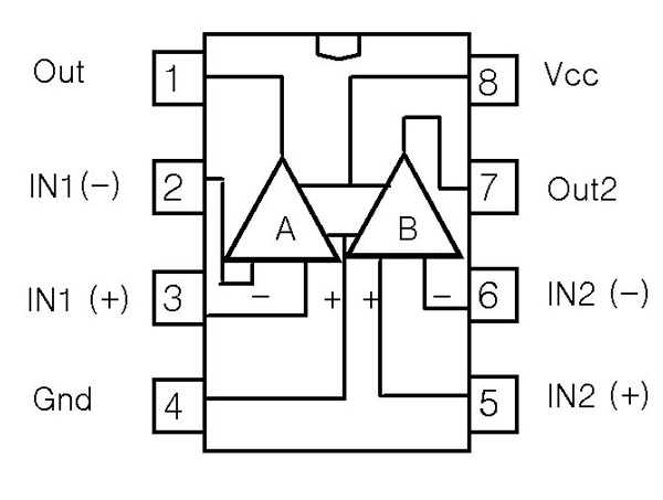
I always prefer Operational amplifier-based input stage to fed in such a high-power amplifier. This will lower down the distortion and give a better gain on stable values. Here I am using JRC4558 operational amplifier, because this chip has two operational amplifiers one can be used to set the gain and other to filter the low frequency signal.
Voltage range ±7 volt to ±15 volts
• Low power consumption
• Low noise
Power supply setup:
I want to design onboard power supply for this system, Both the IC preamplifier and amplifier works on dual voltage. But amplifier IC is of 100watts thus it works on high voltage than preamplifier. We are using ±24volt transformer as input power supply. There are two ways to solve this problem.
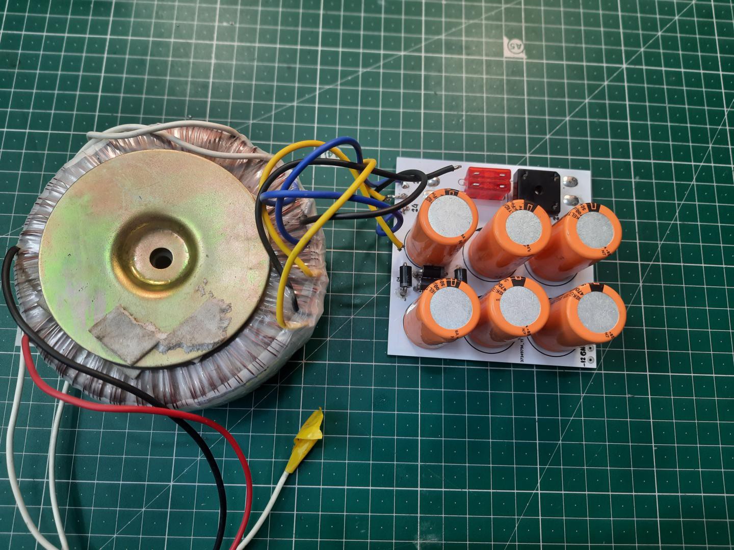
1st to design a circuit with linear voltage regulators available in market, and to get ± 15volts from them. Here 7815 and 7915 can be used as positive and negative voltage regulator respectively.
2nd to buy a dual voltage rating transformer which can output the respective ratings (±15volts) with ±24 volts. One more bridge rectifier circuit is required for this.
Because I am using this for testing the power and audio output, I choose 2nd method and make all the connections with my toroidal transformer which is cable to produce dual voltage at same instant.
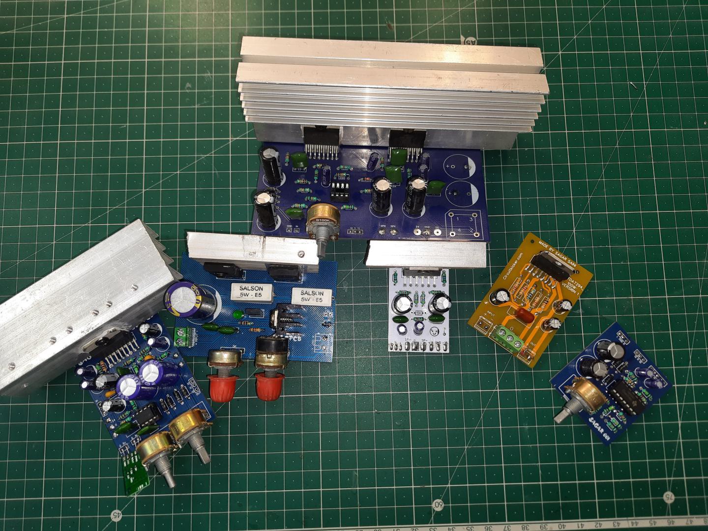
Components used:

1) TDA7294 IC
2) JRC4558 IC
3) 200K, 100K, 150K, 22K, 10K, 2K2, 1K and 330R resistors
4) 100nf, 1nf and 330pf polyester film capacitor
5) 1000uf, 47uf and 4.7uf electrolytic capacitor
6) AMS1117 5Volt
7) IN4007 diode
8) 100k, 47k potentiometer
9) Custom designed PCB
Circuit diagram:
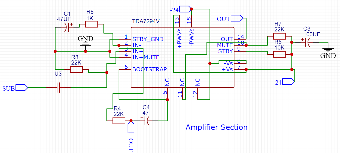
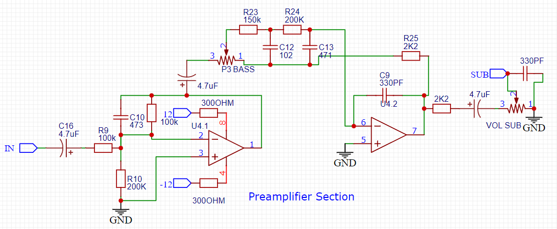
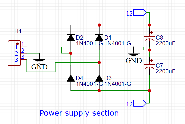
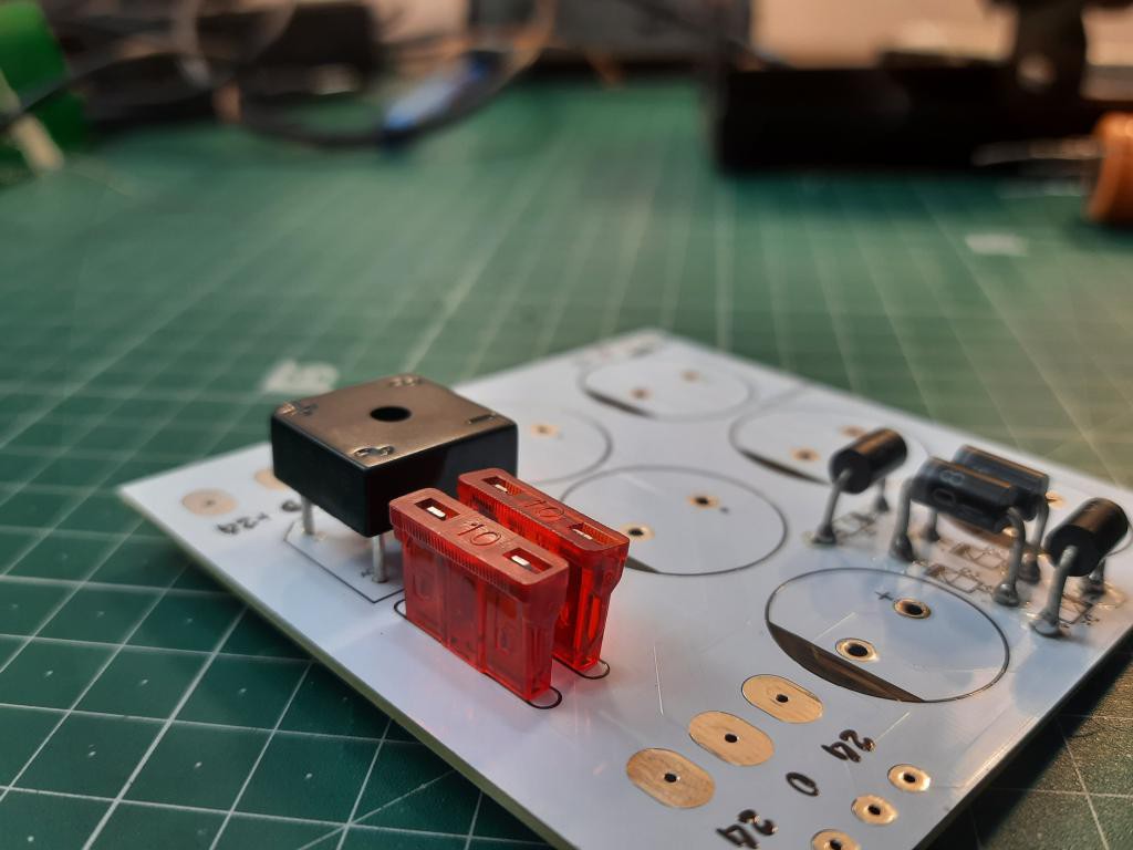
Circuit diagram has 3 sections according to the explained used of IC and onboard power system above. Ams1117 5volt regulator is used to power audio Bluetooth chip. IN4007 and 1000uf capacitor make an onboard filter power supply for preamplifier and Bluetooth. But we need an external rectifier source to fed the main amplifier with ±24volts. Get your hands on high power rectified filtered power supply unit from here.
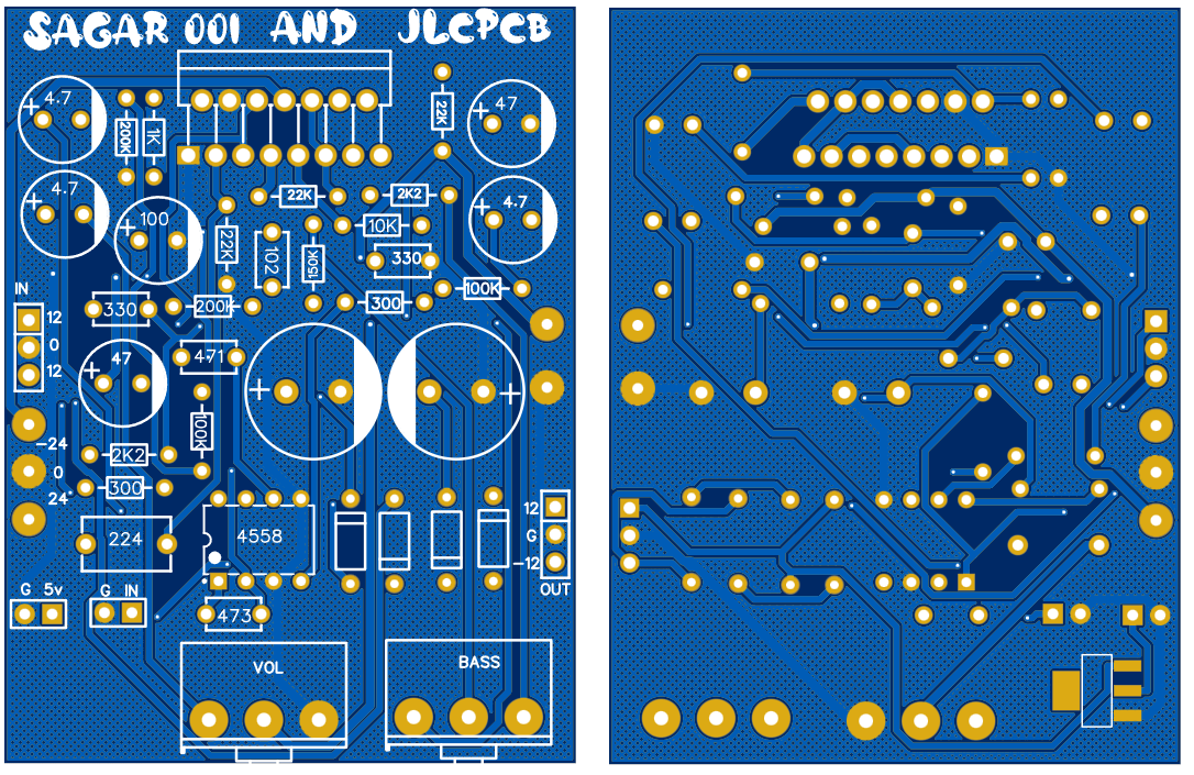
Designing PCB:
Then I started designing my circuit by combining all of three circuits given above. If you want to use same designs as mine then Get them from here.
These PCB is manufactured using JLCPCB...
Read more »
 Lithium ION
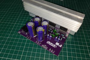
 Sagar 001