Close
0%
0%

Aper-Oculus

A Kria SOM carrier board for high speed digital design

Similar projects worth following
Aper-Oculus is a carrier board for Xilinx’s Kria SOM, focused on delivering a compact and modular solution for makers and professionals targeting high-speed digital design. The board has a plethora of I/O, including FMC, MIPI, and an SLVS-EC connector compatible with FRAMOS’s FSA/FSM architecture. It will be accompanied with example designs and encrypted IP for the SLVS-EC sensors so developers can focus on vision algorithms instead of connectivity.

The Aper-Oculus is an open source hardware project supporting the Xilinx Kria SOM architecture. It most notably provides an FMC connector for up to 4 GTH TX, and 2 RX lanes at 12.5Gbps. This enables it to handle multiple prototyping applications with the Kria SOM.

All aspects of the project except for some IP cores (which will be provided encrypted) will be open source. The board can be programmed via the FTDI controller. SI5332 clocks can be programmed via J12 header. To program the PIC18LF47K42 with your own designs, please use the Microchip adapter and program board as described in the github. A naive implementation is currently in progress, which will be VITA 57.1 compatible by launch date of the crowd supply campaign.

This project handles bare metal for all the below configurations. More to come soon! If there is a specific design you wish to see implemented in the project please reach out.

Currently Supported Aper-Oculus only needed example designs:

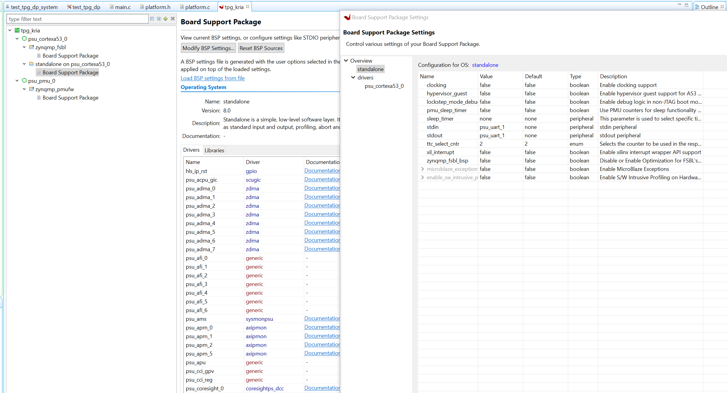
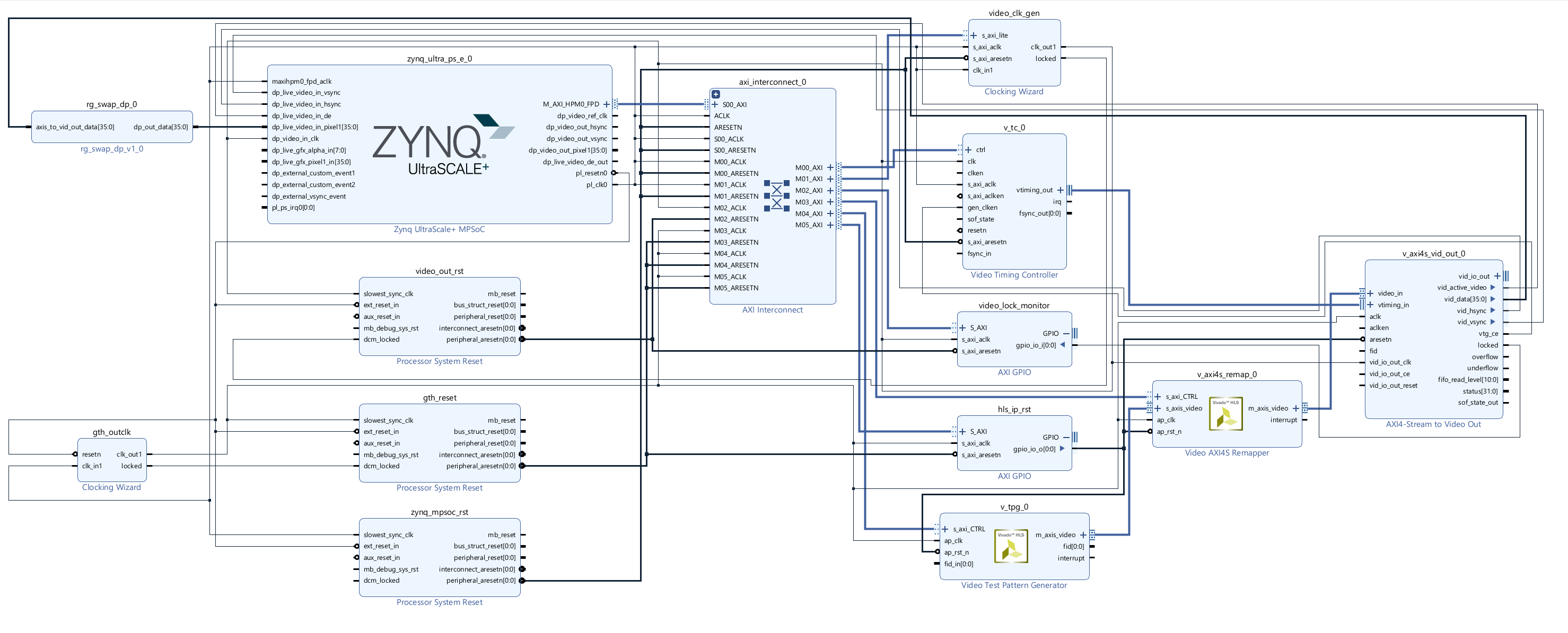
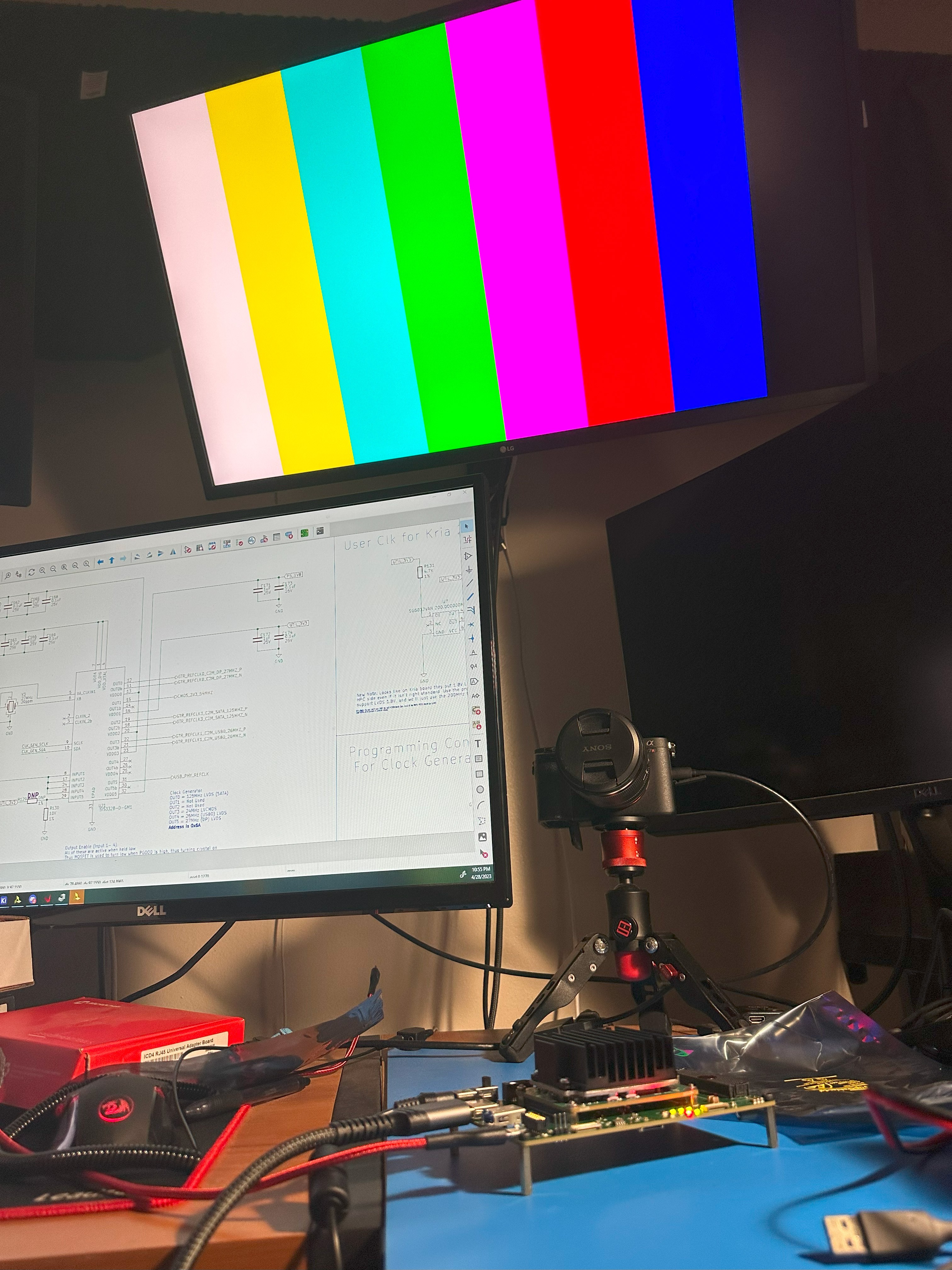
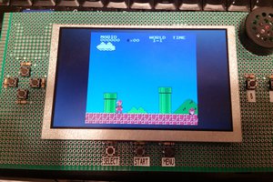
  • TPG to PS DisplayPort
  • MIPI CSI to PS DisplayPort
  • TPG to MIPI DSI
  • PetaLinux build with USB, DisplayPort, and SD

Currently Supported Example Designs with ApotheoTech's APT-C11-FMC (1 Device, 1 Host CoaXPress board):

  • CoaXPress Host 2.0 from Basler Boost Camera to PS DisplayPort
  • CoaXPress Device to Host loopback to DisplayPort
  • MIPI CSI-2 data from Raspberri Pi camera to CoaXPress Device looback to CoaXPress Host to PS DisplayPort (Milestone Implementation)

Future Example Designs with ApotheoTech's APT-C40-FMC (4 Lane CoaXPress Device board in design)

  • TPG to CoaXPress Device x4 lane to CoaXPress Host card (APT-C04-FMC) to suitable FPGA development board (ZCU106)
  • MIPI CSI-2 data from Raspberri Pi camera to CoaXPress Device x4 lane to CoaXPress Host card (APT-C04-FMC) to suitable FPGA development board (ZCU106)

Future Supported Example Designs with ApotheoTech's APT-C04-FMC (4 Lane Host CoaXPress board in design)

  • CoaXPress Host x2 lane to CoaXPress Camera (Using ZCU106 with APT-C40-FMC)

Future Supported Example Designs with ApotheoTech's APT-PIHAT-FMC (in design)

  • Ubuntu build with PetaLinux Wifi enabled. PL for DSI and CSI-2 for expected Pi-Hat interfaces, and GPIO for PiHat. Other GPIO include Xilinx PMODs.

  • 1 × ApotheoTech's Aper-Oculus Kria SOM carrier
  • 1 × Xilinx Kria SOM FPGA SOM platform to drive the Aper-Oculus
  • 1 × Heat Sink for Xilinx Kria SOM Avnet or ApotheoTech's version are fine for most applications
  • 1 × FRAMOS FSM-IMX547 SLVSEC Camera
  • 1 × Raspberry Pi ArduCam Camera used for MIPI applications

View all 9 components

  • Aper-Oculus Teaser Done

    Chance Reimer05/21/2023 at 03:44 0 comments

    Sorry for the delay on hardware updates, I've been working on this promo video using Blender models of the board, and then adding effects in Adobe After Effects. I'm quite proud of the finished results.

    More to come later with PetaLinux and Ubuntu builds for the Aper-Oculus! I'm waiting on an external power supply for a SATA drive so I can prove that all the interfaces work in Linux.

  • Kria GTH Findings and MIPI CSI-2 Working

    Chance Reimer05/06/2023 at 05:25 0 comments

    Crazy cool finding for the Kria SOM: if you save the settings from simulation of another GTH capable Zynq MPSOC (Like say the ZCU104 or ZCU106), you can load the GTH on the Kria SOM with these settings via dynamic reconfiguration, and have it working without issue. The lagging problem I was having with my CoaXPress link was actually from the Basler camera, not the Kria SOM interface. Here is a short snippet of video of me getting CXP 12.5Gbps interface with GTH on Xilinx Kria SOM. The weird redness of the video is due to me not updating/setting gamma manually, and the Basler doing it automatically. Will most likely fix these settings in software when I get to the Ubuntu creation from source.

    The steps to achieve the above are:

    • Setup GTH transceiver in SIM and pull regbase for linerate above 10.3125Gbps
    • In hardware, setup some trigger from AXI4 Lite interface to initiate this transfer
    • ????
    • Profit as we run at a linerate that Xilinx said was unsupported for the Kria SOM.

    This is exciting for a multitude of reasons, the most important being that we surpassed what was considered the "max" speed that the Xilinx Kria K26Cs stated they can handle in the Vivado 2022.2 GUI. I had the stream stable overnight, so I'm not sure why they rate limited this interface. The work around is present for all enthusiasts that need the full bandwidth mentioned on Xilinx documentation.


    On an also exciting note, I have gotten both MIPI interfaces tested working in a 2 lane implementation utilizing a barely changed project from @gtaylormb. Next step is to prove a 4 lane implementation with the IMX477 to completely prove out the Aper-Oculus's D-PHY supported capabilites. If I get some interest, I'll also release a DSI example design with a Raspberry Pi Touch Screen.

    To blatantly state my modifications, I had no use for the TPG, and did not connect the enables to the VTC and AXI4S to Video Out since they are technically unnecessary. The I2C expansion channel, and address were also changed to ensure that they matched with the Aper-Oculus.

    The fork that I used for single lane implementations can be found here to generate on your Aper-Oculus. More detailed instructions will come in a separate post, but the nuts and bolts include:

    1. Create a new Vivado project
    2. Source the block diagram script in the github, and copy in the xdc file
    3. Compile and export hardware as an *.xsa
    4. Launch Vitis, and create a workspace called 'SW' somewhere in your directory. Launch and create a platform project using *.xsa generated on step 3.
    5.  and create the software project from the bitfile, using a platform project. Any of the IMX219 variants should work with @gtaylormb's code, but I specifically have this version.

    Next is getting a PetaLinux build, and an Ubuntu build from source to support the Mali GPU on the board, and then finally SLVS-EC.

  • CoaXPress on the Xilinx Kria SOM

    Chance Reimer05/02/2023 at 16:32 0 comments

    I have gotten my bare metal implementation of the CoaXPress Host and Device IP cores working on the Aper-Oculus. Happy Chance:


    The host side has been verified working with an accredited CXP 2.0 Camera (the Basler Boost). The Device side is tested using a loopback of the Host side to the Device side. I would use Basler's Frame grabber, but their driver doesn't work on Ubuntu 20.04, and I'm too lazy to downgrade just for this test. Maybe I'll make my own PCIe frame grabber just to support 20.04+. That'll show them to support LTS Ubuntu versions!

    It took a bit of troubleshooting to get this working from the ZCU104. First obvious change was the rate limit of 10.3125Gbps for the GTH transceivers which is NOT reflected very well by Xilinx documentation. Their website claims 12.5Gbps for Kria SOMs, but the Vivado GUI disagrees (DS987 of July 07 2022 states 12.5Gbps on page 29, but the GTH GUI's max value is 10.3125Gbps). The nice part is that register setup for GTH transceivers seems to be normalized across Ultrascale+ Parts with GTH transceivers, so there was no need to update my dynamic reconfiguration ROMs. An interesting future test would be to crank the GTH to 12.5Gbps using their register interface, and see if it's stable without the GUI limiting our setup of the register interface.

    Once the pinouts were updated, and the Zynq MPSoC BD part was updated, the next difficult update was the Vitis platform. For some reason, the port kept many of the old address values, and was not reporting correct reads to known version addresses in the UART debug output. The best tips I had for solving these issues were:

    1. Ensure all AXI4 Lite addresses are reset and then re-assigned when you port to an old block diagram to a new architecture.
      1. If you have custom AXI4 Lite IP cores, ensure you're not using more bits than needed for the address port, as this will cause Xilinx to apply more memory than actually needed to address your cores. I'll provide a tutorial on packaging IP with my AXI4 Lite regbase + slave interface at a later date.
    2. When you build the new Vitis project, just make a new one and import the source files. It's not worth it trying to debug old platform projects. Start a clean repo.
    3. Ensure the FPGA is in JTAG programming mode (all boot pins are zero) if you are programming the FPGA via JTAG. You can overwrite the boot mode register and still program it if you load from QSPI or the SD Card, but I found all the AXI addresses were wrong. Weird. If anyone knows why, I'd loved to be enlightened.

    The next interesting finding was using Xilinx's ff.h library's behavior changes based on which logical drive you are writing to. In my original ZCU104 example design, I was writing to logical drive 0, but in the Kria SOM, SD card 0 is reserved to a emmc on the SOM. We must use logical drive 1 to save xml files read from the CoaXPress Device.

    The working code snippet tested on ZCU104 for logical drive 0:

    //Setup vars
    FRESULT Res;
    BYTE work[FF_MAX_SS];
    static FIL fil;
    static FATFS fatfs
    static char *SD_File;
    
    //initialize SD interface
    TCHAR *Path = "0:/"
    Res = f_mount(&fatfs, Path, 0);
    if(Res != FR_OK) {
        return XST_FAILURE;
    }
    
    Res = f_mks(Path, FM_FAT32, 0, work, sizeof work);
    if(Res != FR_OK) {
        return XST_FAILURE;
    }
    
    SD_FILE = (char*)"cam.zip";
    Res = f_open(&fil, SD_File, FA_CREATE_ALWAYS | FA_WRITE | FA_READ);
    
    //Execute necessary control reads as per CXP 2.1 spec to gather xml file
    

    Now, the above works fine for logical drive 0, but when you use logical drive 1, the f_open statement will fail. The solution is to change the above to:

    TCHAR * Path = "1:/";
    
    //.... same
    
    SD_File = (char*)"1:/cam.zip";
    
    //..same

     And everything works again like magic. Why does this work this way? Not sure, but I'm just happy when I get my SD card to grab XML files to read on the computer and for future storing and parsing of the files when I get this design into PetaLinux.


    The only real bug/difference from the ZCU104 implementation and the...

    Read more »

  • With UART All Debugging Is Possible

    Chance Reimer05/01/2023 at 06:01 0 comments

    This update centers around setting up the board support package correctly to get UART working with Xilinx Vitis designs. I was troubled with debugging multiple boards that would not display UART correctly, even though the circuit and FTDI chip were correctly passing all tests.

    UART has plagued me for many years, since my senior design when trying to communicate between an Arduino and a Jetson Nano (pro tip always check your GPIO voltage levels before your nostrils are blessed with the sweet crispy smell of burning ICs), to now with this Kria SOM. Much like back then, some thorough reading of documentation could have saved me a few hours of troubleshooting, but apparently I prefer life in constant pain and stress and pressed forward blindly into the unknown with multi-meter probes and a few ILAs. My guess was that I could see some variability on the multi meter on the UART lines to clue me in if the IC was damaged and not appropriately converting the signals the the FTDI 3.3V domain.

    After staring at steady voltage level probes for longer than I would like to admit, I eventually broke down and googled. I found a thread created back in 2015, cluing me in that default BSPs must have some peripheral interfaces selected before it will actually use them. Apparently I had been living my life in sweet bliss, coddled by Xilinx's nicely packaged BSPs for their development boards when creating previous designs, and now I find myself thrust into the cold of custom PCB design, a place where there is no love, and hope is a distant memory.

    If you or a loved one is in a situation where your UART interface doesn't work with a Xilinx FPGA on a board you created, you should take a deep breath and follow the below steps:

    1. Open up your Vitis Application Project, and navigate to BSP settings
    2. Select the platform, and navigate to the appropriate BSP (I'm using the standalone_psu_cortexa53_0 for example).
    3. Select modify BSP settings
    4. Go to stdin, stdout, and select the peripheral that you want to use.


    Edit: After messing around some more, I've found out that if you specify UART in the Zynq MPSoC block diagram element before generating your Vitis Application, the BSP will normally choose for you. The above checklist is still useful if you ever forgot to initialize the UART in the BD and added it later, after generating the Vitis platform project. 


    CoaXPress is now working on the Aper-Oculus. This might be one of the first Kria SOM's that's interfaced with a Basler Boost! Coming soon.

  • Summon the ColorBars

    Chance Reimer04/29/2023 at 05:02 0 comments

    The board's peripheral ICs are programmed, and voltages look good. It is now time to summon the unholy color bars, and truly bless the Omnissiah with its glory. We'll be doing this using a Xilinx Block Diagram, leveraging the Test Pattern Generator, AXI4S to Video Out, and Xilinx's own PS-GTR Displayport IP Block.

    The high level block diagram schematic looks like this:


    The above uses the video axi4s remap for no other reason than a previously misguided attempt to only use 1 pixel per clock while attempting to design a CoaXPress Host output. You could remove the axis remap without issue, and plug the TPG directly into the video for axi4s out. I noticed that the axi4s to video out to the PS-GTR has strange color flipping, which I fixed with a quickly added IP to swap the correct bits. These are both added in the github, using a project creation TCL file, and by pulling the RG_Swap IP in the same top directory. Run the TCL files by using:
    source TPG_3840_Test.tcl

    If you're using windows, I recommend pulling the files to the C:/ directory, as Vivado can generate some impressively long file paths. If you're using Linux, do whatever you want.

    The C code to program the project should be opened in Xilinx Vitis. To create this project you should create an platform project, import the exported hardware file from Vivado, and then follow the prompts. After this is done, create an empty application project and import the software files found in the githubs SW directory.

    With both of these programmed, you can actually program the Aper-Oculus directly from Vitis, via the FT4232H, regardless of the mode pins. It ends up looking like this:

    with a bouncing box slowly going across the screen. If the FT4232 UART was working correctly, I would be able to change the TPG pattern via UART, using a menu based callback configuration, seen on many of Xilinx's Example Designs. Again, I'll debug the UART later.


    One strange finding from programming the Kria is the ERROR_OUT status from PMU. To find the error status registers, you must be in debug mode, and select the APU in the debug window.

    Then, scroll down to find the error_status registers, 1 and 2. More information can be found about them in UG1085. I'm not sure why pmu_service is flagging as an error. I'm not even really sure why it cannot access ROM? What ROM? Is this possibly something referencing the EEPROM on the board? I'll investigate more later to try to figure this out. If anyone knows, it'd be a huge help, and turning off this obnoxious red led.

    The next update will be proving the CoaXPress Host to a CXP camera using my FMC board. See you there!

  • Programming Peripherals - Debugging Entry 2

    Chance Reimer04/27/2023 at 06:14 0 comments

    Now somewhat confident this board won't explode in my face and singe my hot-cheeto encrusted stubble, I move on to the making this shiny paperweight actually usable. There are 3 chips of interest on the board that we would like to program to enable complete functionality of the Aper-Oculus, and these include, the FTDI 4232H, the PIC18LF47K42, and the SI5332 clock generator.


    The only real unknown when I started this project was how to get the FTDI chip working as expected, as the USB to JTAG program was closely guarded. I was planning to rip from the Xilinx Kria SOM development board EEPROMs, but thankfully I took so long with this project that Xilinx released a tool called program_ftdi that does this for you without all the hassle of using the FT_PROG.

    The steps to program the FTDI EEPROM are amazingly simple:

    1. If using the Aper-Oculus, make sure that the Kria SOM is plugged in correctly (read the above section).
    2. Plug in the micro-USB connector to the host PC (ensure that the USB Vbus has no shorts before doing this so you don't damage your PC's USB port).
    3. Open Vivado 2022.2 (I'm not actually sure which version this was supported, but this is the one I'm using)
    4. type into the Tcl Console, "program_ftdi -write -ftdi FT2232H -serial 0ABC01 -vendor "my vendor co" -board "my board" -desc "my product desc". Of note, the -vendor, -board, and -desc must all be lower case or you'll receive an error.
    5. Profit.

    Once the FTDI chip is programmed, you will be able to autodetect the board in Vivado reliably, and program with it. I'm still unable to get UART up on Port B of the FT4232H device, which is perplexing, but once my Oscilloscope comes in, I will probe the bus to try to figure out what the issues are.


    Next is the PIC on the board for power control. This needs to comply with the power up sequence specified in the KV260 Vision AI Starter Guide (UG1089) as this was the only place that I found that describes the functionality of the power up sequence.
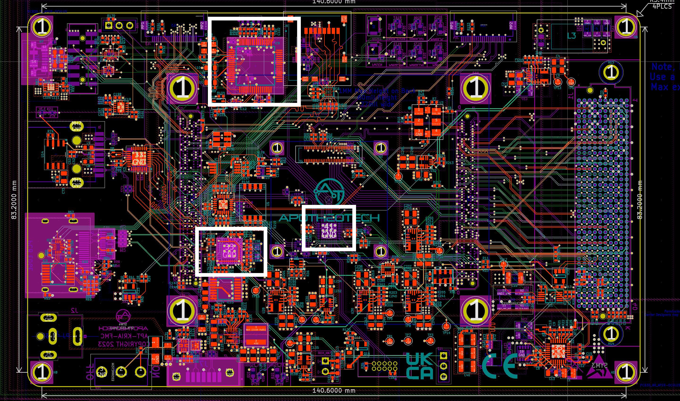
    I'm actually brand new to PICs, and was unfamiliar with their interface, however, was able to still get the project running in about an hour thanks to ChatGPT, Github Copilot, and MPLab's Code Creator. Check the github repo for the latest software for the PIC, as it is super naive at the moment and only handles the initial power up and reset sequences. The end goal for the PIC is to have a fully compliant VITA 57.1 EEPROM IPMI parser + a function to program the VADJ MAX15301 chip.

    To program your own, you'll need a programmer converter, specifically the AC102015, using the Cortex JTAG/SWD header (J4) and connect it to J15 on the board. Next you'll need a suitable PIC programmer, I am using the ICD4.

    Steps to program are:

    1. Plug in the AC102015 J4 to J15
    2. Plug the AC102015 to ICD4
    3. Power on Aper-Oculus (with or without Kria SOM applied)
    4. Power on ICD4
    5. Program and flash from MPLabs

    I'd recommend checking all PIC code using MPLab's debugger, or by probing resistors for resets. If the code is incorrect and asserts PS_POR_B forever, the FPGA will not be able to boot, so be careful troubleshooting.


    The PS side of the FPGA requires 3 clocks to support all the interfaces that I have broken out on the Aper-Oculus. The schematic can be found on the "PS_Clocks.kicad_sch" page, and basically copies the same SI5332 layout that was on the original Kria Carrier board. To program this part, you must have Sky Work's Clock Builder Pro installed. I also have this project in the Github repository, in ~/SW/SI5332_Clock_builder. To program you must have the Sky Works programmer, and you should connect pins 1, 3 and 7 to the Aper-Oculus J12.

    To program this device you must:

    1. Connect the appropriate programmer to Aper-Oculus
    2. Power on Aper-Oculus
    3. Power on programmer
    4. In Clock Builder, select (program NVM), which will take the place of (No EVB Present) when Programmer is powered up and plugged into computer.
    5. The default I2C address of the chip is 0x6A, but be careful with your project as you can accidentally...
    Read more »

  • Received the Boards - Debugging Entry 1

    Chance Reimer04/27/2023 at 05:52 0 comments

    The boards have finally arrived. The past 12 months have been a mixture of waiting for parts, software design for FPGA IP Cores (harder than expected) and communicating to a thankfully perceptive PCBWay for fixing possible part conflicts with my BOM. I probably should have been keeping a better log of respins, however, I wasn't sure how interesting an update of, "changing part due to shortage" or, "Oh this is how to do JTAG the correct way with an FMC" would have been to an average purveyor of the dark arts of electronics. But now all that has changed. The boards have arrived. The rails aren't shorted. The LEDs turn on. It's time... to test some hardware!


    The first thing I had to do with the incoming boards was replace an inductor. It couldn't be sourced in China, and the shipping tariffs cost for only 20 dollars in parts may induce seizures in those who are frugally inclined. DigiKey has a really great article on it here that I used with this hot air reflow station, which worked well for soldering the inductor. The Cliff Notes of soldering an IC with hidden pads are:

    • apply no clean tack flux
    • tin pads
    • apply heat to pads until they glisten and begin to flow on the pads. It's obvious when you see the solder "bubble up"
    • slap on the IC in hopefully the correct orientation

    The power up sequence of the Kria SOM means that I needed to do some soldering to pull the enables for the PL and PS side voltage regulators to 5V to check their voltages before connecting it to the Kria SOM. The Aper-Oculus requires a 12V brick with a 5.5mm plug. I have currently  only tested it with this brick, but be warned it doesn't include the wall plug, so you have to buy this from Amazon to make it usable. Checking the voltage was quick and easy, and all my regulators were the correct voltage except for the SLVS-EC, which appears to have been given the wrong resistor during production, which was most likely a communication issue between PCBWay and I, but easy enough to fix.

    After testing all the boards, it was found that one of them most likely has a bad IC14 (MP5016), and the 12V line won't power on. I ordered some from Mouser, and will re-solder a new IC later to salvage the board.

    Next, is programming all the necessary IC to program and boot the Kria SOM, which I'll provide in another update.

View all 7 project logs

Enjoy this project?

Share

Discussions

Similar Projects

Does this project spark your interest?

Become a member to follow this project and never miss any updates