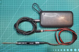
The Power Supply is made up of a 60W USB C PD powerbank and a pair of USB-C negotiator modules, that negotiate for the 20V@3A (60W) profile.
One is connected to the powerbank and feeds the output through two high current diodes to a super capacitor bank (8x 2.7V 10F) and from there into the UDOO Bolt. The other one presents the charging port to the outside and connects through a third diode into the capacitor bank as well.
When switching between internal and external powersupply - as the power delivery is being negotiated - the short powersupply dropout is buffered by the capacitor bank.
The power from the external USB-C PD negotiator module is also directly (before the diodes) fed into a different USB PD negotiator module that feeds into the powerbank for charging.
The switches on the power side control (from left to right):
- System power
- Screen power
- Mainbus power (includes charging)
The charging module had to be left disconnected from the powerbank due to it leaking considerable amounts of charge while it was connected and not being charged. So for charging, even if the system isn't powered on, the mainbus switch needs to be activated.
Two Pi Picos (one for each half) read the key matrices. Both are connected to each other via serial UART and one is connected to USB.
Switches are Gateron blues and the keyboard "cases" are filled with some silicone to soften the sound of the keys.
The trackball is an old PS2 optical mouse where i soldered the buttons and wheel on the opposite side of the PCB; using a steel ball suspended over the optical sensor as the trackball. The Arduino on board the UDOO Bolt reads it using the PS2 protocol. While the system is still shut off, using the right mouse button on the trackball causes the system to power on.
The frame is made from 2020 Aluminum X profiles, using standard mounting hardware such as T-nuts and corner connectors, while everything else is 3D printed PLA.


 Robert Mordzon
 Clara Hobbs
 Stefan Wagner
rely love the design i think im going to try to make a similar one anything you learned in using it i should be aware off