Conway's Game of Life
This project implements well known Conway's Game of Life.
Note that this implementation uses Periodic Boundary Conditions to simulate a field of an infinite size, i.e. each boundary is connected to the opposite boundary. This makes algorithm a bit more complex to implement but it mimics better the intent of this game.
How to play
First, you need to setup the initial lives (first generation) on the 8x8 LED matrix.
For that, you use 2 knobs (potentiometers) to point to a cell (blinking LED) and a button to change its state (alive or not).
You can define the first generation any way you see fit.
Once you are done with first generation setup, you can start the game by pressing the START button.
Then, generations get calculated and displayed, one after another, at regular intervals (speed is controllable through the left knob used in the previous setup stage), from a few hundred ms to a few seconds.
The START button can also be used to pause the game, then resume it at a later time.
The situation where we reach a generation with no cells alive, is detected and a smiley displayed to show that.
If the system reaches a stable situation (with live cells that never change), this is indicated by blinking those cells.
The following video demonstrates all that:
Circuit & Prototypes
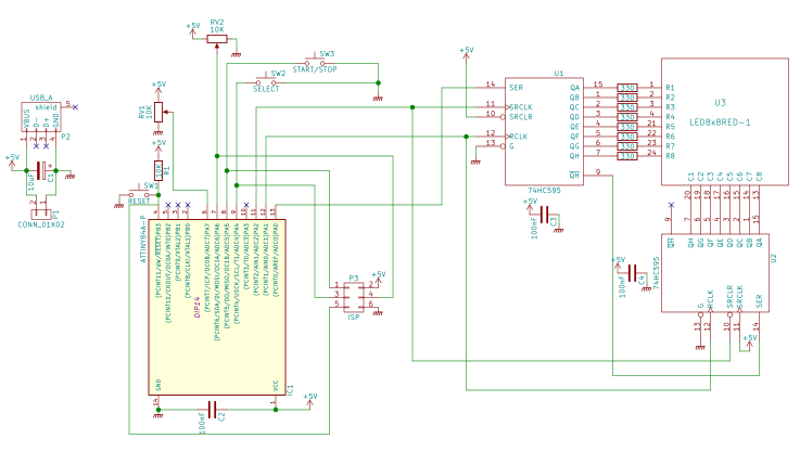
The circuit is based on an ATmel ATtiny84A AVR MCU that contains all logic.
The ATtiny84A has 8KB flash (code and init data) and 512 bytes RAM (for static and local variables in stack), hence a smaller MCU like ATtiny24 (2KB flash and 128 bytes RAM) would work as well, but I did not have any in my drawers, hence I did not test it.
The ATtiny84 is a tiny MCU with "only" 11 available IO pins (digital and some analogic).
Hence addressing an 8x8 LED matrix is better done using SIPO (Serial In, Parallel Out) shift registers, I used 2 chained 74HC595, one for matrix rows (LED anodes), the other for the columns (LED cathodes). I added current-limiting resistors to all 8 columns, to avoid roasting the MCU. Wiring for this takes only 3 digital output pins of the MCU (data, clock and latch).
LED matrix addressing is done though multiplexing (display one complete row at a time during a few ms, then display the next row, and so on). If all rows get "swept" fast enough, then human eye persistence makes you think all the matrix is displayed at the same time. I determined (after experiments) that showing each row during 2ms, then handling the next, i.e. 16ms to display all 8 rows, was the longest delay I could use. In the final program, I use 1ms for that duration.
For 1st generation setup, I originally used 3 push buttons, one Previous/Next pair to position the "cursor" (blinking LED) to the cell which we want to change state (dead or alive), then one button to switch the state of currently selected cell. This worked fine but that made the first phase very slow to setup for the end user. Wiring here required 3 digital inputs (one per button).
I hence decided to use 2 rotating knobs (potentiometers), just like the famous "Etch a Sketch" toy, to go faster to a position in the matrix. I kept one push button for changing the state of the currently selected cell. Wiring then took 2 analog input pins and 1 digital input pin.
An analog joystick with a button on top would probably be the ideal device for this, but I did not have one at disposal. Anyway, the program and the wiring should remain the same (or roughly so for the wiring).
The circuit has another button, used to start the game (used to tell the system that setup of the first generation is finished) and also suspend it at any time, then resume it.
Finally, to make the project a bit more challenging, trying to use the last available byte of code, I decided to reuse one of the pots used for initial setup for controlling game speed.
Here are the schematics for this circuit (made with KiCAD):
My first prototype was originally developed on an Arduino UNO (it uses an ATmega328P, compatible with ATtiny, with just more pins, more bytes...
Read more » Jean-François Poilpret

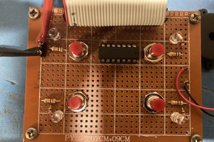
 jimshortz
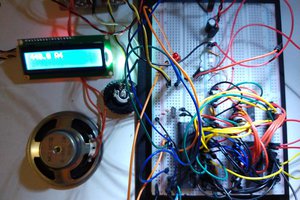
 Ken Yap
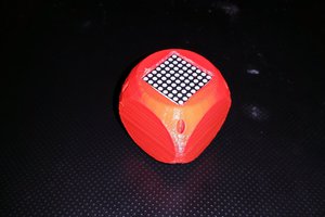
 Ford Sleeman
 Jim Shortz
Hi Yann, calculating the full popcount was intentional, to be consistent at this level of computation. I did not change the rules of the game though, I just rephrased them to fit the whole count:
- any count other than 3 or 4 means a dead cell
- a count of 3 means that the cell must be live, whatever its previous state
- a count of 4 means that the cell must keep its previous state
This is what is implemented based on the ok and code flags returned by the neighbours() method.
I have already checked several standard patterns (still life, glider, periodic) that fit the 8x8 board, and it works fine.
Regarding inlining, this is already done thanks to the GCC options I use during compile and link time. If I look at the produced assembly, the whole program has only the following functions:
- AbstractButton::_unique_press() not part of the algorithm
- Matrix8x8Multiplexer::refresh() not part of the algorithm
- main() contains all the rest, including the whole game algorithm inlined
As of now, with current code size of 908 bytes, I don't think I'll need to further optimize the code, as the only feature I want to add now is the possibility to change the speed of generation evolution with one of the existing pots.
Another test I will do is to improve the current code so it can be parametered further to handle other matrix sizes; then I'll check the new code size for a 16x16 matrix.