Let's start by a video
the idea
I had an old wiper motor made by Bosch. It's the same type as this one.
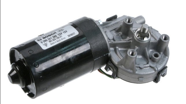
They are very powerful, they draw 2 to 3A, do not run very fast but have really a lot of torque, much more than what I would ever need to rotate a solar tracker (even a big size one !).
However these motors are DC ones without any solution to control their position.
So I decided to add a cheap 12bits magnetic encoder AS5600
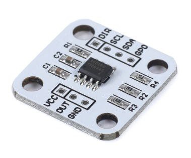
This chip is equiped with a precise hall sensor and allows to detect the angualr position of a diametric magnet "flying" above it (ideally less than 3mm above the chip).
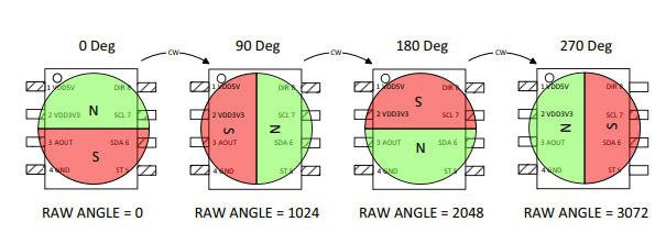
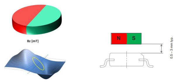
I decided to install the magnet directly on the motor shaft (not the wiper shaft) to get the maximum precision.
mounting the magnet
The first operation was to cut the end cap of the motor to access the motor shaft.
Unmount the motor, remove the cover. Then drill the bottom (not the bearing...) and finish grinding it so that the shaft will be visible.
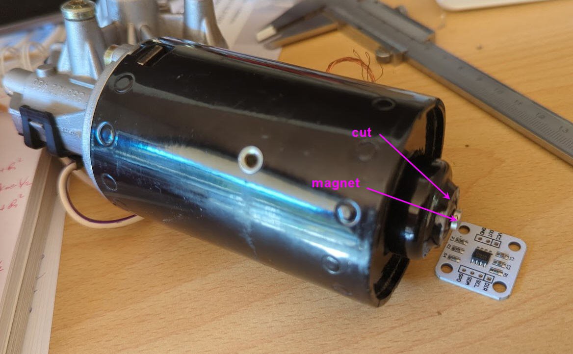
Now, print the sensor holder and glue it in place.
Also on thingiverse: https://www.thingiverse.com/thing:5552935
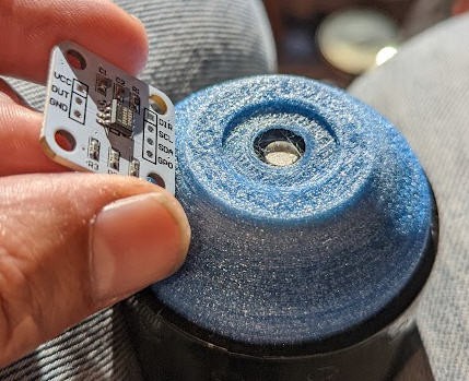
And finally glue the magnet and fix the sensor in place
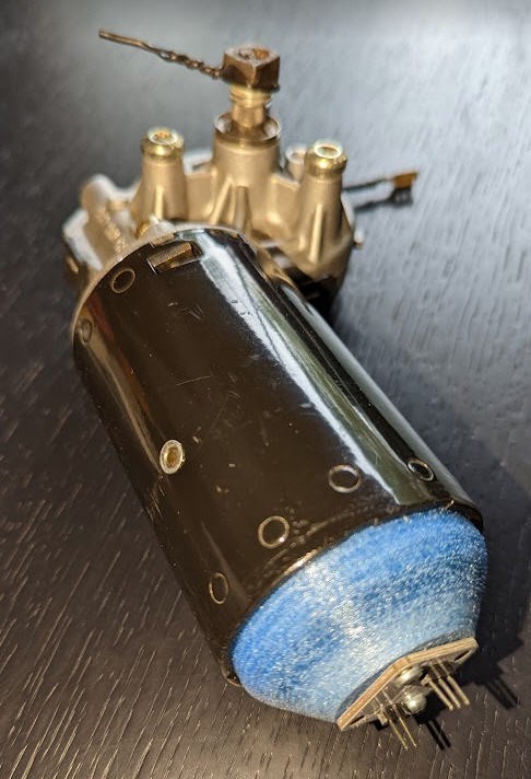
Your motor is now a servo motor !
wiring the AS5600
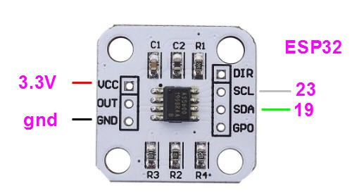
this device is an I2C sensor and needs only 4 pins to interface with ESP32 MCU
Adding a driver board
To drive this motor you will need a quite powerful H bridge driver. I chose the IBT-2 chineese driver.
It's a very powerful one said to handle 43A.
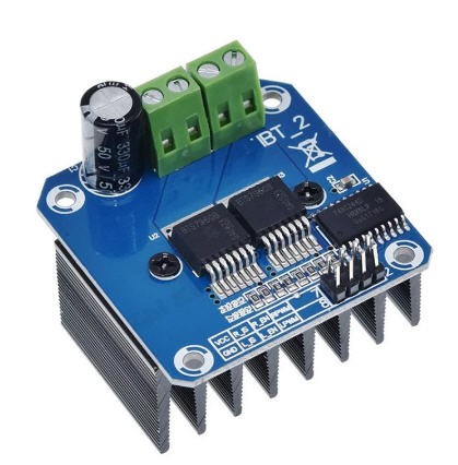
It's composed of two half bridges BTN7970
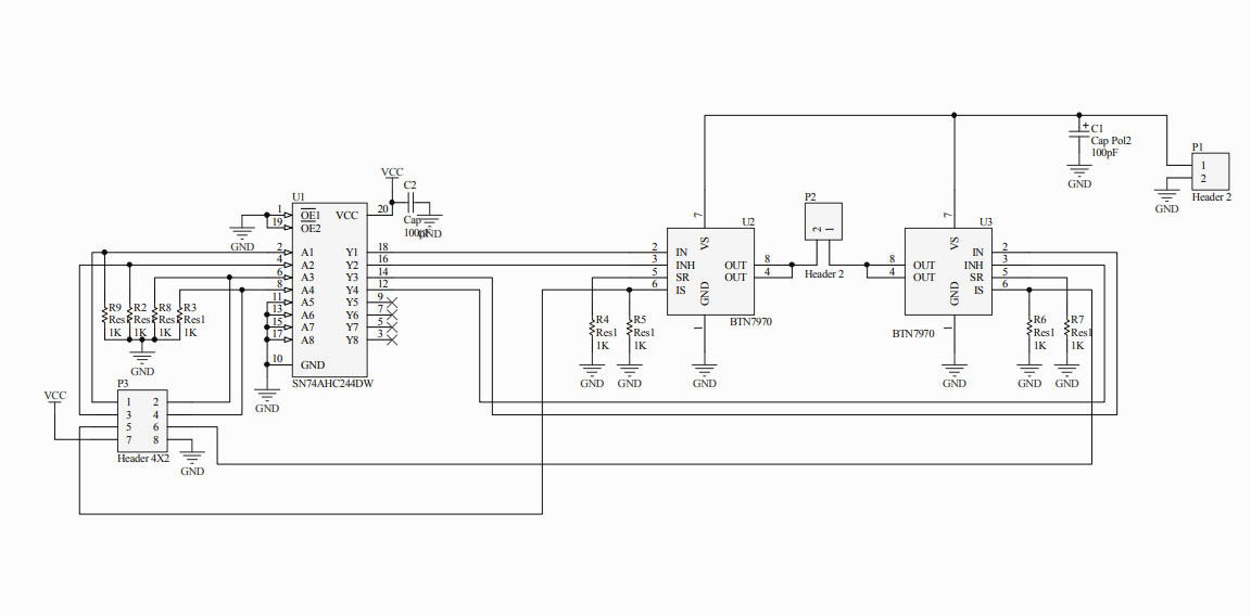
Using this chip is quite easy. I followed this excellent tutorial but replaced the arduino by an ESP32.
Wiring IBT-2 with ESP32
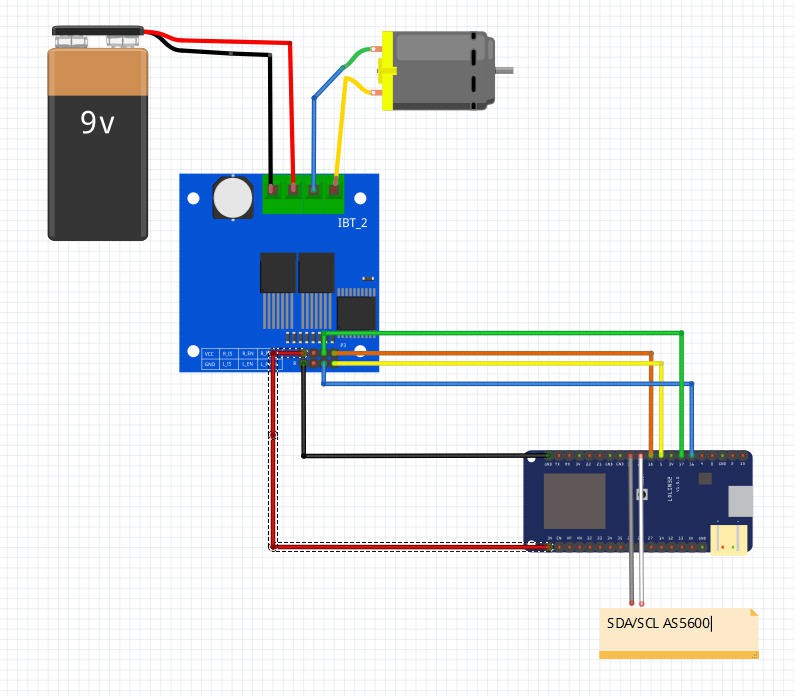
The big terminal blocks are connected to the motor and the DC power (12V in reality !)
The pin headers are connected as on the drawing to the ESP32 pins
- IBT-2 pins 7 (VCC) to ESP32 3.3V (yes it works at 3.3V)
- IBT-2 pin 8 (GND) to GND (both 12V ground and ESP32 ground)
- IBT-2 pins 5 (R_IS) and 6 (L_IS) not connected
- IBT-2 pin 1 (RPWM) to ESP32 pin 18 (PWM output pin for Right half bridge)
- IBT-2 pin 2 (LPWM) to ESP32 pin 5 (PWM output pin for Right half bridge))
- IBT-2 pin 3 (EN_R) to ESP32 pin 17 ( Enable pins R )
- IBT-2 pin 4 (EN_L) to ESP32 pin 16 ( Enable pins L )
ESP32 firmware
Example firmware is available on my Github
The code is extremely simple and only shows how to read the sensor, drive the motor and apply a PID control loop to precisely position the motor at any number of turn you want (integer + fractional turn of the motor shaft).
reading the AS5600
I do use Rob Tillard's AS5600 library. It is really simple and does the job !
A few lines are enough to read the sensor and detect "zero crossing" for full rotations counting:
 //AS5600


  rawValue = as5600.readAngle();
  if (((rawValue - prevRawValue) < -999) && CW) nbRot++ ; //apply hysteresis to detect each full rotation (4095 <--> 0)
  if (((rawValue - prevRawValue) > 999) && !CW) nbRot-- ;


  prevRawValue = rawValue; //save the rawValue for next iteration
driving the motor
no library but simple code as well !
two PWM signals enter Left and Right H bridges.
void runMotor(void)
{
  if (pwmSpeed > 0)
  {
    ledcWrite(0, pwmSpeed);
    ledcWrite(1, 0);
    CW = true;
  }
  else
  {
    ledcWrite(0, 0);
    ledcWrite(1, -pwmSpeed);
    CW = false;
  }
}
the pwmSpeed variable can be positive or negative. Positive is for CW rotation and negative CCW.
each pwm signal has a range 0-2047 on 11 bits and a frequancy of 24kHz
They are "hardware PWM" embeded into the ESP32
  ledcAttachPin(RPWM_PIN, 0); // assign PWM pins to channels
  ledcAttachPin(LPWM_PIN, 1); // assign PWM pins to channels
  // Initialize channels : ledcSetup(uint8_t channel, uint32_t freq, uint8_t resolution_bits);
  ledcSetup(0, 24000, 11); // 24 kHz PWM, 11-bit resolution (range 0-2047)
  ledcSetup(1, 24000, 11);
Now that we can rotate the...
Read more » JP Gleyzes


 Laura
Laura
 Kevin LO
 Paul Fjare
 shane.snipe
Hey, thanks for the clear tutorial and useful prints! I have made one of these myself, and it mostly works great!
However, I am having one issue. Every now and then (about once every 30 seconds on average) the function as5600.readAngle() gets stuck and takes 1002ms to return. I have this issue both with your example code, as well as with my own implementation. Of course this completely messes up my readings, as in the meanwhile the motor has made multiple revolutions and I've lost track of the position of the output shaft.
Have you had this problem, or might you know what's going on?
I'm running this on an ESP32 btw..
Thanks!