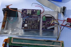
The main part of the clock is a 24 channel EL wire sequencer and power supply. A Micrel MIC4826 chip is used to convert 3.3VDC up to about 140VPP to power the EL wire. A series of 24 TLP168J Photo-Triacs switch power to the selected wires. The Photo Triacs are controlled by a discrete logic implementation of a 24 bit SPI interface that is driven by an NXP LPC1114 MCU demo board. A Trimble GPS Copernicus II GPS module in the upper right corner of the board will set the clock on power up and once a day. Input power will be 9VAC from a wall wart.
I did the electronic design and laid out the board last summer, and got the bare boards back. Due to time constraints, I had to wait until the last few days to start building the boards. I populated the power supplies (3.3V and 144V) and the SPI interface last weekend. Both power supplies work as expected. I have not tested the SPI interface yet or installed the Photo Triacs yet. I bridged two of the Photo Triacs for testing the EL wire power supply and installed a piece of the wire.
This is the first time that I have worked with EL wire, and have not found anything like a real data sheet on the wire that I got. When I built the high voltage power supply, I set the output frequency to about 160Hz. After connecting the wire, it was plain that it was not bright enough. I raised the frequency to about 500Hz and it was a little brighter, but not bright enough. Next, I raised the frequency to 1.2KHz and it is brighter, but still not bright enough. From the Micrel data sheet, it looks like 1.2KHz is about as high as I can go with this power chip. The voltage is about 144VPP or about 50VRMS. Does anybody know what voltage and frequency people are using to get good visibility from the wire? Do you get acceptable life out of the wire still?
 Bharbour


 Thomas Flayols
 Nick Sayer

 Muth
Muth
I have a project using microchip HV809 and a discrete boost converter, I am able to run a meter of EL at 360Vpp and 2.5khz. I can help you make that work if you like.