Close
0%
0%

RT Soldering pen

Soldering pen for Weller RT tips with OLED display

vlkvlk
Public Chat
Similar projects worth following
Every hardware hacker need good soldering tool. My idea was to build own but with very specific qualities. On one side not so expensive, on second side high quality and also small with precise control and features. I found some projects where is used Weller soldering tips designed for WMRP soldering iron with standard 3.5mm jack and inside the tip is also thermocouple for sensing temperature. These tips are not so cheap but the quality is really great, especially for fine soldering. Hardware design is based on similar projects but with many modifications and improvements. Also my request was to make the hardware small as possible to fit into handle and capable to supply from hobbyist LiPO battery.Buy one on tindiy: https://www.tindie.com/products/vlk/rt-soldering-pen/

Features:

  • very compact - will fit into handle
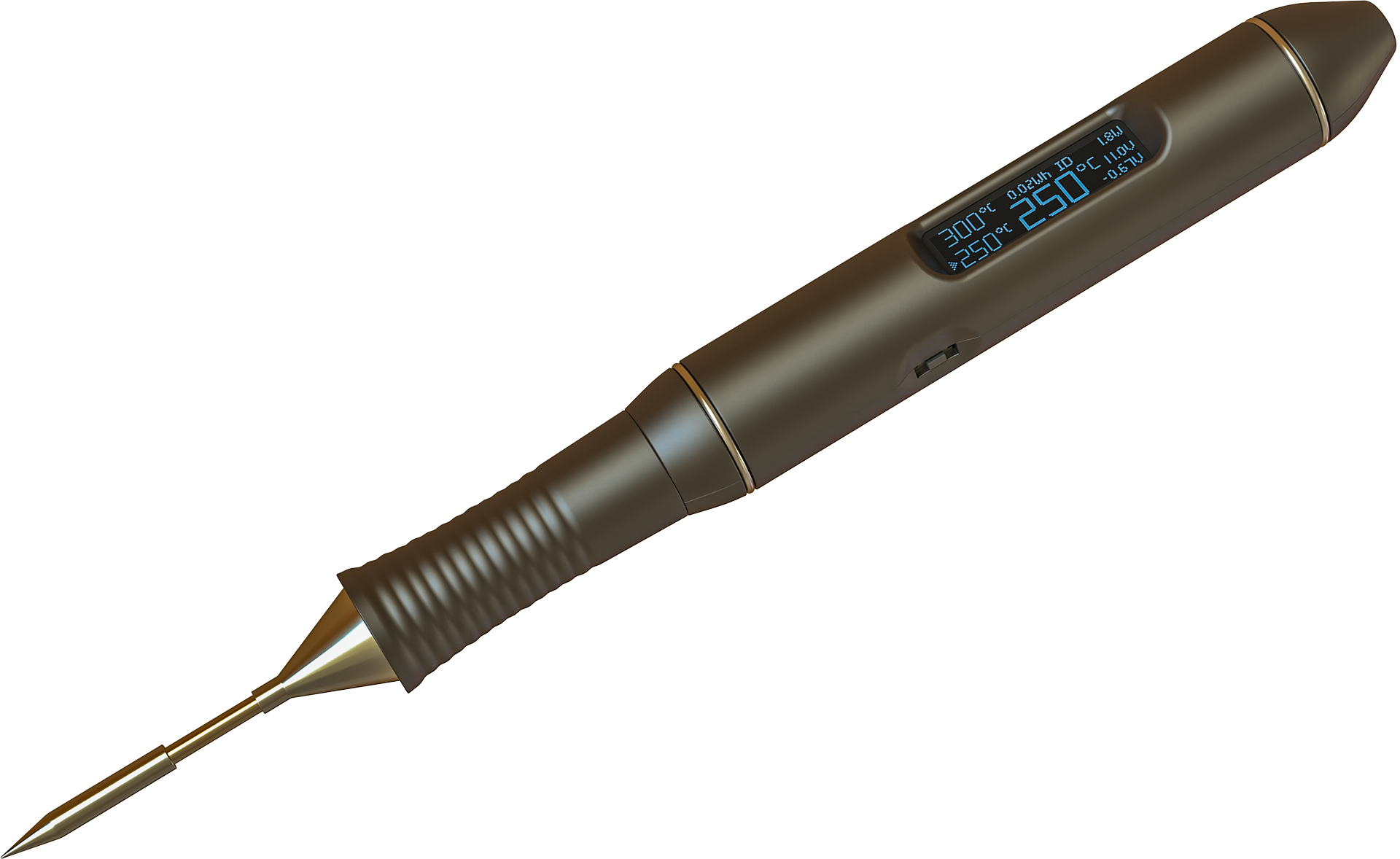
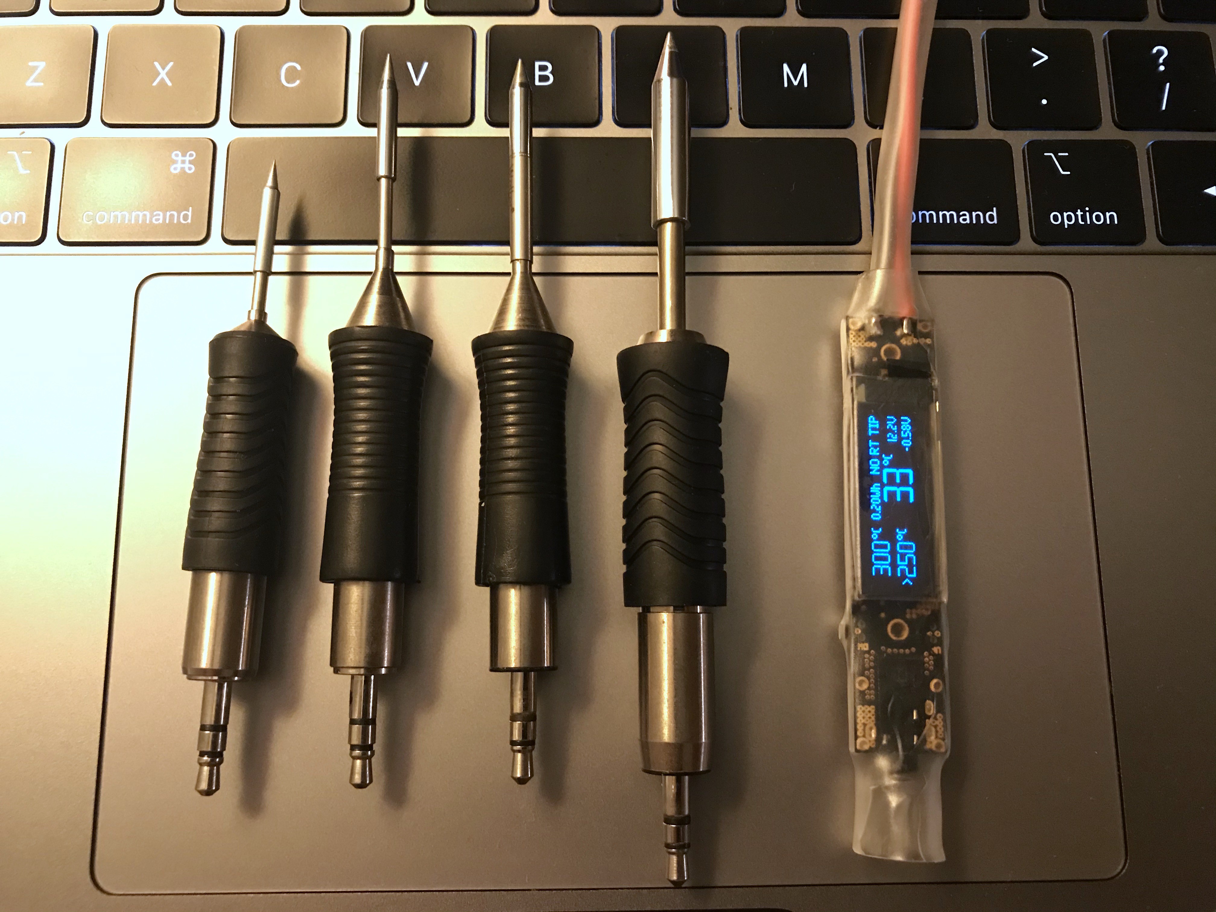
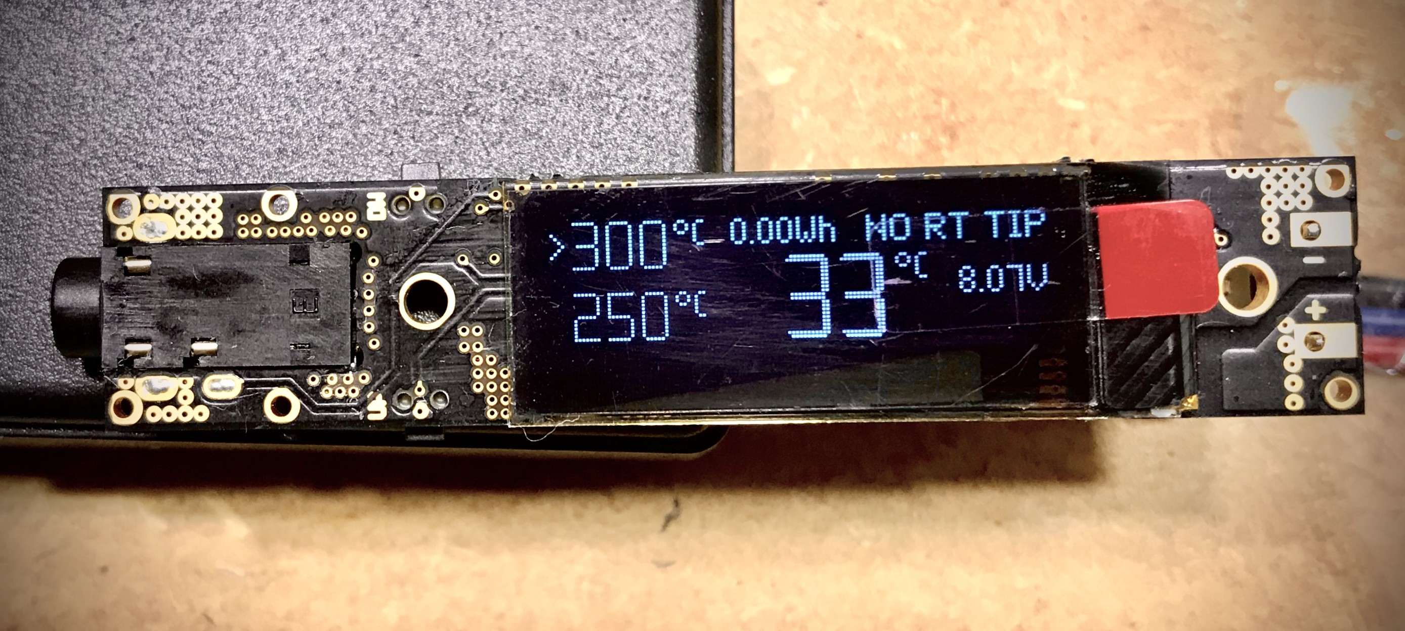
  • display show status, preset and tip temperature, power, supply voltage, drop, ...
  • two buttons
  • automatic standby
  • sensing supply voltage and tip current
  • precise regulation with PID (PSD controller with some modifications)
  • supply voltage is from 5V to 18V (best is 10-13V)
  • designed to supply from LIPO battery 2S (7.4V max is about 18W) or 3S (11.1V max is more than 40W)
  • calculating consumed Wh
  • heat-up in 5sec from 25 to 400°C (with 40W limit)
  • Idle current about 8mA

What is planed:

  • case
  • battery monitor (warn when battery need charge)
  • configuration editor for some constants from PSD controller, power limit, ....
  • open-source everything

Videos:

Weller-RT6-Holder-Bottom-V1.0.stl

RT pen case bottom part for HW v1.0

Standard Tesselated Geometry - 9.53 MB - 12/08/2019 at 19:15

Download

Weller-RT6-Holder-Top-V1.0.stl

RT pen case Top part for HW 1.0

Standard Tesselated Geometry - 4.78 MB - 12/08/2019 at 19:15

Download

Portable Network Graphics (PNG) - 64.37 kB - 03/30/2017 at 19:45

Preview
Download

  • 1 × STM32F031 Microprocessors, Microcontrollers, DSPs / ARM, RISC-Based Microcontrollers
  • 1 × AD8551 Precise operational amplifier
  • 1 × ACS711 Hall effect current sensor
  • 1 × LMR14203 Power Management ICs / Switching Regulators and Controllers
  • 1 × OLED display 0.91" 128x32

  • Display replacement

    vlk05/02/2023 at 09:25 0 comments
  • New HW revision v1.1

    vlk02/08/2021 at 21:00 0 comments

    - new switches

    - updated layout with fixed current sensor connection bug

  • RT PEN CASE

    vlk12/08/2019 at 19:22 4 comments

    Otto Winter send me STL files with case design for HW v1.0

    Bottom part: Weller-RT6-Holder-Bottom-V1.0.stl

    Top part: Weller-RT6-Holder-Top-V1.0.stl

  • About new RT tips

    vlk12/08/2019 at 18:55 0 comments

    RTM, RTP and RTU tips

    Weller this year introduced new series of RT tips with nice slogan "No compromise".

    There are three types:

    • RTM - RT Micro - they are same like previous line RT, but with new naming
    • RTP - RT Pico - these tips are smaller, shorter for more precise soldering
    • RTU - RT Ultra - these tips are in opposite bigger and designed for higher power (till 150 Watts)

    All the tips have same pinout and in general are compatible,

    RTM and RTP (also previous RT) have resistance of heating element 2 Ohm and they are designed for 12 V (current is 6 A) but maximum average heating power is 40 Watts - this power is controlled and limited by PWM.

    RTU has resistance of heating element 3.5 Ohm, this mean, to reach 150Watts is necessary to use higher voltage - at least 24V, but the current will be still similar - what is good for the JACK connector.

    But actual design of RT soldering pen has limitation for power at 18 V and current to RT, RTM and RTP will be at 18 V: 9 Amps - the pen it should withstand it, because average pulse power is limited by SW to 40 W) question is what can withstand the JACK connector.

    The main question is how to use this with RTU tips they need 24 V. so, absolute maximum rating of HW 1.0* is 25V for supply voltage (limiting element is input capacitor) after replacing input cap next limit will be 30V (maximum voltage of MOSFET switches)

    *Absolute maximum rating for previous HW v0.3 is 20V - this is limited by 20V MOSFET switch.

    For RTU if the supply will be 24V then output power can be near to 150 Watts, but this need also modifications in SW to allow higher output power. Yes, this is planed and new release will available be soon.

    Another problem with new tips is that each kind RT/RTM, RTP and RTU has different dimensions of the cylinder on JACK side and is necessary to count with this for case design. (old RT and new RTM have same dimensions of the cylinder) this is also reason why Weller sell for each kind different tip holder.

    MS tips:

    If I talking about tips there is one more question: What it mean if in name is "MS", it mean that tip meets Military Specifications. But there is no more informations. In general the main different is that shield of the tip is electrically isolated from the connector, standard tips have shield connected to ground.

    Weller RT TIP typemax average powerheater element resistancecurrent  and power at 12Vcurrent and power at 16Vcurrent and power at 24V
    RTM / RT40W (55W*)6A / 72W8A / 128W-
    RTP
    40W6A / 72W8A / 128W-
    RTU150W3.5Ω3.4A / 41W4.6A / 73W6.8A / 164W

    * some RT tips have 55W limit (RTM 36 S / RT 11)

    from left: RTP, RTM, RTM MS, RTU

  • New RT tips

    vlk10/06/2019 at 20:14 1 comment

    just found, that Weller announced new RT soldering tips

  • New firmware v0.4.0

    vlk10/06/2019 at 20:06 0 comments

    New firmware is ready to download, it support HW v0.3 and also new HW v1.0.

    features:

     - display brightness control

    - turn off display to protect pixels burning when is inactive for 15 minutes (wake up by pressing both buttons at once)

    - increased maximum preset temperature to 500°C (only for HW v1.0)

    https://github.com/pavelrevak/rt_soldering_pen/releases

  • New redesign is ready

    vlk09/26/2019 at 18:30 1 comment

  • New HW

    vlk05/07/2019 at 18:36 3 comments

    After longer delay, after some troubles, new revision is getting ready.

    There will be two major enhancements:

    • full reverse polarity protection
    • added accelerometer

    Stay tuned..

  • New version of Firmware v0.2.0

    vlk08/09/2018 at 18:14 0 comments

    Main changes:

    - improved PID

    - saving preset temperatures

    List of all changes and download: https://github.com/pavelrevak/rt_soldering_pen/releases

  • New version of Firmware v0.1.0

    vlk07/24/2018 at 21:29 0 comments

    Although is still in development state is stable and has many new features, like simple main screen with large temperature, Fahrenheit mode or left-handed mode.

    There is also many features in background

    Update is easy and safe with any SWD (ST-Link) programmer

    Download from github: https://github.com/pavelrevak/rt_soldering_pen/releases


    Updating firmware with cheap Chinese ST-Link programmer:

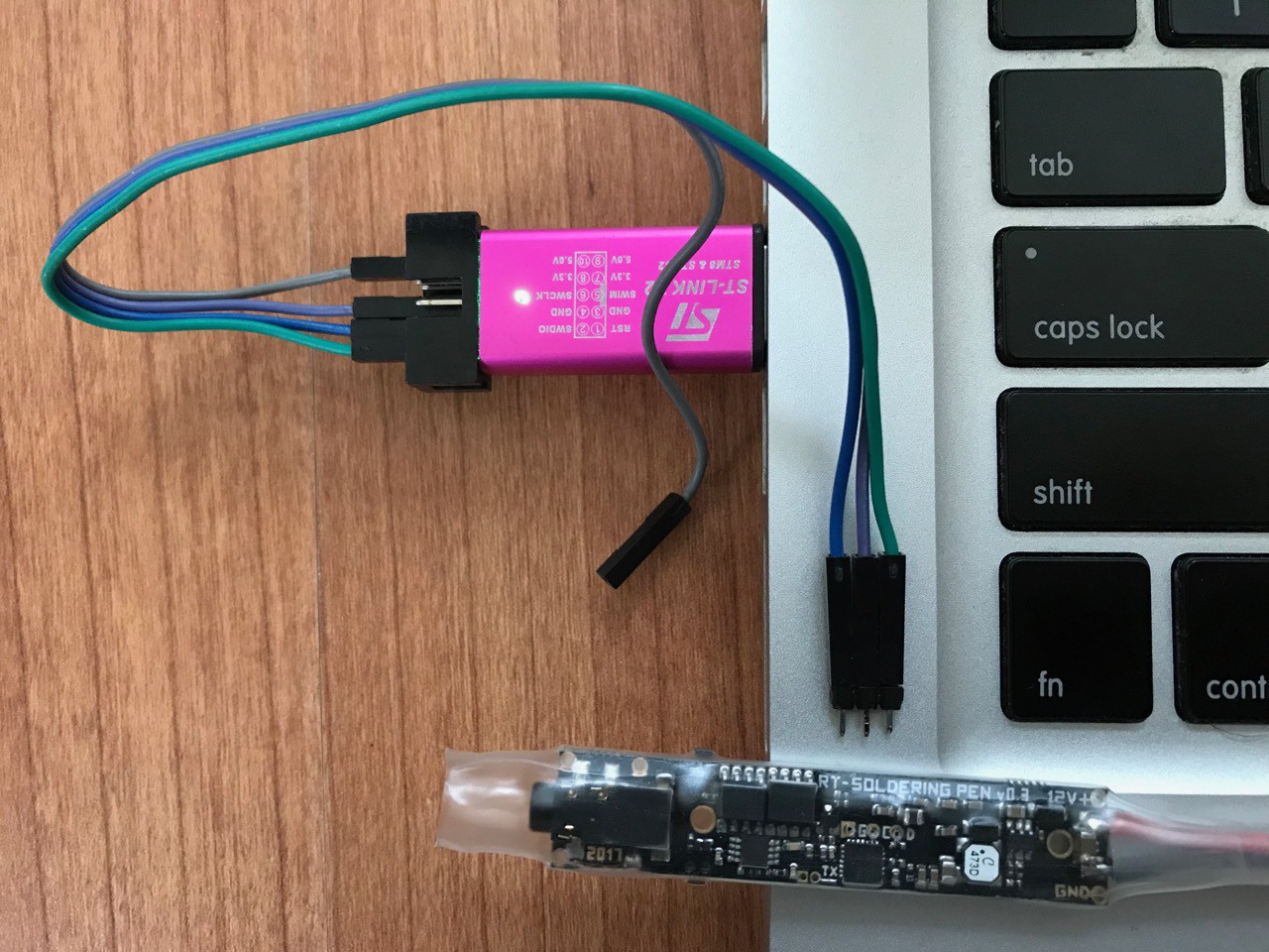
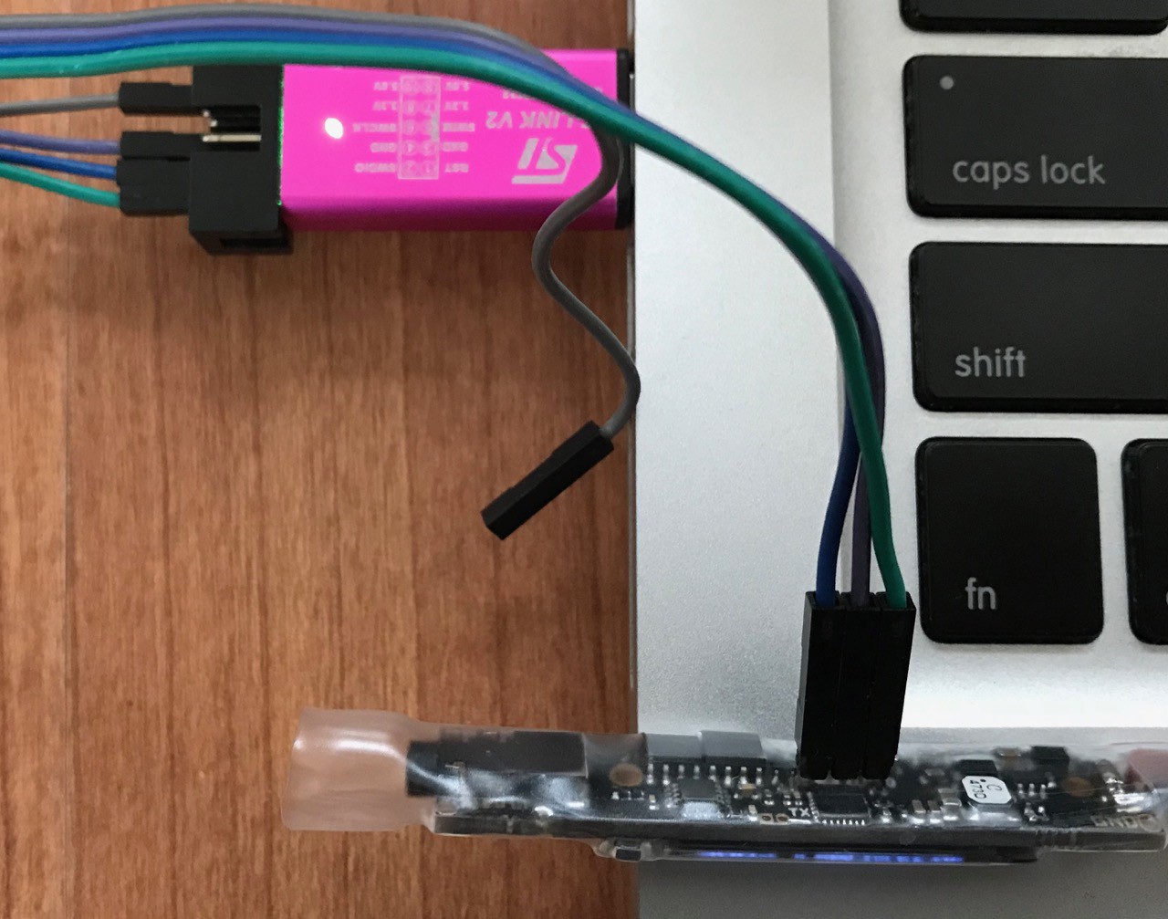
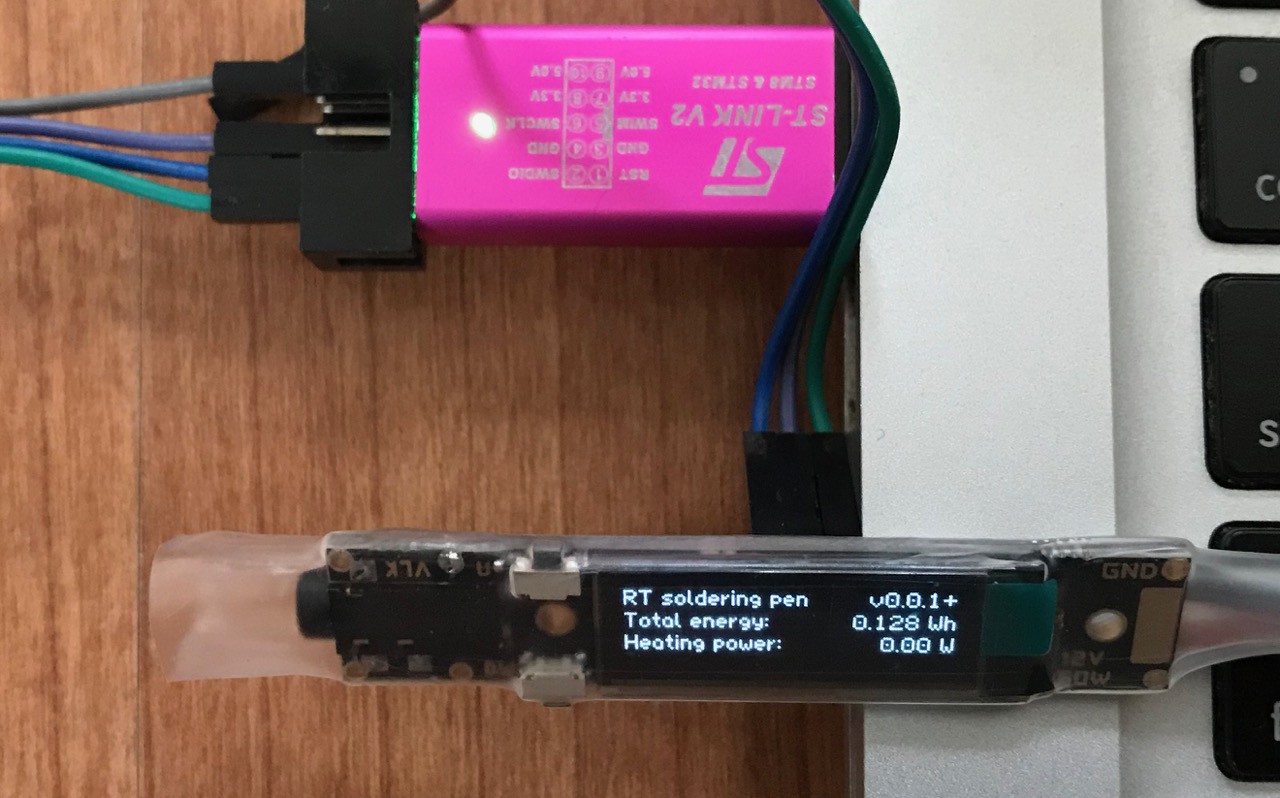
    To program, use ST-Link utility from ST, or any other SW for Flashing STM32 micro-controllers (openocd, texane/stlink, pystlink, ...)

    There is also possible to use ST-Link part of any Discovery or Nucleo board.

View all 18 project logs

Enjoy this project?

Share

Discussions

[deleted]

[this comment has been deleted]

vlk wrote 06/26/2018 at 10:46 point

No, it is not a clone, it is completely created from scratch (HW and SW), it uses different MCU, also have current sensor, for better diagnostic and more precise regulation and also it can operate at lover voltages, faster heating (4s). Also biggest advantage are Weller tips, and is made in EU. On other side there is no USB.

  Are you sure? yes | no

Rens wrote 04/14/2018 at 00:09 point

Hi,

very nice project, any plans to make the PCB available.

  Are you sure? yes | no

Albert Green wrote 03/14/2018 at 20:04 point

Are you using the I2C version of the 128x32 OLED display? Where do you buy it? I cannot find a source for it. buydisplay.com seems to sell only the SPI version. And on Aliexpress/ebay the I2C version seems only available soldered on an adapter PCB.

  Are you sure? yes | no

vlk wrote 03/26/2018 at 06:15 point

Hello, there are also on ebay: https://www.ebay.com/sch/i.html?_nkw=0.91+ssd1306

  Are you sure? yes | no

Bodzio wrote 02/15/2018 at 18:03 point

You have a bug in the project. Weller uses a D-type thermocouple in the tips no K-type !

K type thermocouple in 500 'C has voltage 20.644 mV, but D type 8,077mV.


  Are you sure? yes | no

vlk wrote 02/15/2018 at 22:45 point

Thanks! You right, The equation is hope correct, but the type of the thermocouple in schematic is wrong. I will fix this.

  Are you sure? yes | no

Otto Winter wrote 02/07/2018 at 16:25 point

It looks very good, if you get it running, please tell me, how can i get 1-2 finished PCBs!
Best Regards
Otto W.

  Are you sure? yes | no

Paulo Bruckmann wrote 02/06/2018 at 13:38 point

I'm amazed how you fit all in that size, I am guessing you used 4 layer board. I'm designing  one for Arduino with usb ,accelerometer , buzzer (take a look at my profile).  My problem is that  a ts100 for 45$ and I I'm aware that is not the same thing. But this is the price of one RT tip :/ . 

  Are you sure? yes | no

vlk wrote 02/06/2018 at 19:13 point

Hi I saw your version, nice renderings and also case.

Regarding PCB, yes! it is 2 (TWO) layers, design was not easy and I spend lot of time optimizing for high current. Most problematic was ground to keep it strong from one side to another.

TS-100 is nice, but Weller tips are TIPs and if anyone at least once tried Weller then he know that soldering with that is quite different (better). TS-100 is also heavier and bigger, tip is also longer and not so good for very precise soldering. Also need higher voltage for work. (for RT only 12V with 50W and is working from 7V with 18W)

Cheapest Weller station cost more than €300 ?

RT tips are in discount, so the price is now quite better.

  Are you sure? yes | no

Paulo Bruckmann wrote 02/06/2018 at 19:56 point

I don't own a weller RT tip yet, neither a TS100, but already worked with other weller irons. I wasn't sure if it is going to be a big difference. The parts and labour seemed to be an investment.
But now that you print me out the picture, I may continue the project. I always wanted a mobile friendly soldering iron.

Oh! It's 2 layers! You got skills, and I know what you talking about when you say optimizing! What was the minimum footprint, 0603s?  I may switch my 0805s resistors to 0603s. I also using the oled version of 11 pin

I let the power traces without solder mask so they get solder tinned in the fabrication.

I use kicad, if you have the all parts in 3D ( I designed the display) it renders in realtime, it's mind-blowing, isn't it? You don't believe it but my last board layout was built from scratch in less than 2 hours. push  & shove power! 

Thank you for your Reply . Regards!

  Are you sure? yes | no

HP (@banjohat) wrote 02/06/2018 at 13:33 point

Interesting! This reminds me of my own project ;) https://hackaday.io/project/10140-soldering-pen
Out of curiosity - how did you end up with that mini-jack?

  Are you sure? yes | no

vlk wrote 02/06/2018 at 14:38 point

Hi HP,

Thanks!

Yes I know your project, my is inspired by yours and also other similar projects (but desktop versions) and also by TS-100.

About JACK connector, I changed the connector to another because this one needs thin plated slots which was problem with many PCB manufacturers, or it was too expensive.

  Are you sure? yes | no

HP (@banjohat) wrote 02/06/2018 at 14:40 point

Very interesting! I kept that one because I really favoered the co-planarity of the connector. However, I haven't been able to find anything rated for 2A which is needed by the tip. I guess that's not a problem for you if you use another one - is that still co-planar?

  Are you sure? yes | no

vlk wrote 02/06/2018 at 18:47 point

The connector is http://www.cui.com/product/resource/sj-3501-smt.pdf and it has two spring contacts and also two pins for ground then two contacts and pins for TIP (heater) and one for mid pin (sensor) so, I think this will be better. So if one contact is rated for 1A then two contacts can transfer 2Amps. and I don't connect under high current, so static current can withstand much higher. Previous version with old connector (on picture) I checked with IR camera and the connector was cold, hottest place was BUCK converter, MCU and chip on OLED display.

  Are you sure? yes | no

René Arts wrote 06/26/2018 at 15:17 point

If you would want to improve the connector; I have found a nice one which is rated for 5A continuous: search for FCR1295 S9/BBB stereo 3.5mm mini jack socket, it is available i.e. at Conrad and Farnell. Nice project by the way, I'm thinking of buying one!

  Are you sure? yes | no

solankidharmesh40 wrote 01/16/2018 at 20:12 point

just love this project 😍😍😍😍

  Are you sure? yes | no

Makerdog wrote 12/31/2017 at 09:48 point

Vlk I want this thing, I hope it still in progress. Otto Winter, your Design is very beautiful I Love it 

  Are you sure? yes | no

Otto Winter wrote 01/22/2018 at 22:26 point

Thx. ...unfortunately nothing going forward, it is still frozen :-(

  Are you sure? yes | no

JK wrote 11/13/2017 at 19:44 point

Still any updates?

  Are you sure? yes | no

Jez wrote 07/10/2017 at 20:28 point

vlk... Any updates to this???

  Are you sure? yes | no

Paulo Bruckmann wrote 06/01/2017 at 20:32 point

Thank you for your inspiration, I am working in something similar with gyroscope, buzzer and usb port  http://imgur.com/a/mpkse  

  Are you sure? yes | no

Paulo Bruckmann wrote 05/23/2017 at 22:02 point

Any update? What about a buzzer? 

  Are you sure? yes | no

Kees Hessels wrote 05/19/2017 at 19:12 point

Great idea, might be a good project to use Pyralux, so you can curve it to the casing.  Cool project, well done. 

  Are you sure? yes | no

Muphins wrote 05/18/2017 at 11:49 point

This is AWESOME !

On the finished product you could even put a magnet to have a MagSafe-type power connection. Not sure if it would be really useful but at least it would be cool.

  Are you sure? yes | no

Chrischi wrote 05/18/2017 at 02:53 point

Isn't the Mini TS100 nearly the same? (https://www.banggood.com/MINI-TS100-Digital-OLED-Programable-Interface-DC-5525-Soldering-Iron-Station-Built-in-STM32-Chip-p-984214.html)

What differences to the TS100 are you want to archive?

  Are you sure? yes | no

B4Me wrote 05/18/2017 at 06:56 point

More watts 

  Are you sure? yes | no

Chrischi wrote 05/18/2017 at 13:32 point

I like this Soldering Pen but the TS100 has 65W and i think this one 40W.

maybe Otto can clarify this.

  Are you sure? yes | no

René Arts wrote 05/18/2017 at 13:26 point

Being able to use high quality Weller RT tips, which are easy to change without the nasty burnt chicken smell ;-)

  Are you sure? yes | no

Chrischi wrote 05/18/2017 at 13:33 point

word!

  Are you sure? yes | no

jaromir.sukuba wrote 05/19/2017 at 14:26 point

Well, sometimes people like to build something for for the sake of creative process, not to outperform somebody else. It's called hobby and I'm kind of glad nobody questions value of raw paper in my stamps collection.

  Are you sure? yes | no

Chrischi wrote 05/19/2017 at 14:28 point

full ack. 

by the way if anyone misunderstand me, i LOVE this project.

  Are you sure? yes | no

Aisha Farsi wrote 05/17/2017 at 23:22 point

I would definitely pay for one, or two, I really would.

  Are you sure? yes | no

Otto Winter wrote 05/01/2017 at 10:32 point

The 0.84 Inch Display has a resolution of 96x16 pixel (your Schematics specifikation)!
OLED Display with a resolution of 128x32 pixel is 0.91 Inch...
Witch is implemented?

  Are you sure? yes | no

vlk wrote 05/01/2017 at 15:14 point

Hello Otto, thanks for info, It is mistake caused by that I have one sample with 0.84" display 96x16 pixels and on pictures is version with bigger display 0.91"

  Are you sure? yes | no

Otto Winter wrote 04/30/2017 at 20:03 point

Hello Leuven,
can i bay the finished unit?
Best Regards owsuisse

  Are you sure? yes | no

vlk wrote 05/01/2017 at 15:22 point

Thanks for interest, I have some plans with selling this and I hope it will be soon.

  Are you sure? yes | no

Otto Winter wrote 05/20/2017 at 00:31 point

If you can give me the PCB dimensions. i would design a case for 3D printing or other manufacturing formats like molding or milling etc.
For prototyping is the best way 3D printing with Laser sintering technology.
You can see a preliminary picture here:


This is the Display area with two buttons to configuration.


With right click on the Pictures, "View graphic" you can see it in a full resolution!

  Are you sure? yes | no

René Arts wrote 04/19/2017 at 12:57 point

This looks great, I'd love to see more of it! 

  Are you sure? yes | no

Similar Projects

Does this project spark your interest?

Become a member to follow this project and never miss any updates