Close
0%
0%

Multi-FOC:A Universal multi-channel FOC controller

A Universal multi-channal FOC controller for robot systems or Multi-motor collaborative control

Public Chat
Similar projects worth following
Inspired by SimpleFOC, this project tries to design a more efficient, integrated and tiny multi-channel FOC controller that is suitable for most robot systems. I hope you can use it in your drone, AGV, or other robot , it will be cool!

Lisence:CC BY-NC-SA
Funding:the Postgraduate Research & Practice Innovation Program of Jiangsu Province (No. SJCX22_1042)

Project has following characteristics:
1:With a high level of integration!
2:With a nice execution efficiency !
3:with a sufficient expansion interface!
4:WIth a tiny size and weigh!

In introduction you can get more information, if you like this project please let me konw, or you have suggestions/questions, I will hear, anything you want to say you can leave a message on the public channel or talk to me, I will reply you in time!

—引言—

—introduction—

WHY SHOULD USE FOC IN YOUR ROBOT?
为什么要将FOC引入机器人系统中?
WHAT ADVANTAGES CAN FOC PROVIDE?
FOC能够带来什么样的优势?
WHAT KIND OF APPLICATION CAN FOC USE?
FOC能够满足什么样的应用需求?


Strictly speaking, the algorithm implementation of FOC is more complex than that of PWM,but FOC can still provide excellent torque control for BLDC at low speeds. In addition,Its speed switching is very smooth in high speed and low speed. Meanwhile, this also makes the operation of the DC brushless motor controlled by FOC quieter. 

严格来说,FOC的算法复杂度远超PWM控制,但FOC能够为无刷电机在低速运动时带来提供极致的转矩控制能力,其无论在低速还是高速工作下的转换非常丝滑,此外,相比PWM驱动的无刷电机,其噪音得到了明显的抑制。

Therefore, FOC control has naturally become the preferred solution for advanced robot control, making direct drive, collaboration, and protection easier.

因此,FOC控制自然成为了机器人先进控制的重要解决方案,它使直驱、协同、保护更容易。

The following figure shows the typical application of FOC in the field of robotics:

下图展示了FOC在机器人领域的诸多应用场景:

DJI reduces drone noise and improves dynamic performance during high-speed flight through FOC.
大疆通过FOC提高了无人机的动态性能以及静音性。
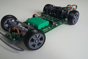
FOC has been preliminarily applied to four-wheel independent drive of AGV.
FOC被广泛应用于四轮驱动的AGV小车中。
The dynamic response and the collaborative ability make quadruped can run flexibly
得益于FOC的动态性能以及多电机协同控制能力,四足机器人能够流畅的奔跑
FOC provides gentle torque feedback and motion protection, making exoskeletons safer
FOC提供了更柔和的力矩反馈以及运动保护,使得外骨骼更加安全

However, existing open-source FOC controllers generally have the following defects:

然而,现有的开源FOC控制器普遍存在以下问题:

1. Insufficient integration: Mainstream FOC schemes such as simpleFOC or Odrive mostly only support fewer parallel FOC outputs. For applications such as AGV, AUV, or quadruped robots, multiple FOC controllers need to be connected in parallel, and reliability still needs to be improved
1.集成度较为不足:诸如simpleFOC或Odrive等主流的FOC控制器,仅支持较少的并行FOC输出,针对AGV、AUV或四足等动辄四个电机甚至更多电机的应用场合,需要通过多个控制器并行连接,可靠性有待提高。
2. Poor execution efficiency: The mainstream FOC solutions are implemented through software algorithms, but the Park transform...
Read more »

datasheet.zip

A summary of datasheet which used in program. update time: 2023/5/16

x-zip-compressed - 12.19 MB - 05/16/2023 at 11:39

Download

Mulit-FOC.xlsx

BOM table:Record the required part number, quantity, and package form, so be careful not to buy the wrong part and package,update time:2023/4/19

sheet - 11.98 kB - 04/19/2023 at 08:36

Download

Mulit_FOC.pdf

The latest version of the schematic,update time:2023/4/18

Adobe Portable Document Format - 1.19 MB - 04/18/2023 at 12:10

Preview
Download

SVPWM_driver.pdf

The latest version of the schematic,update time:2023/8/7

Adobe Portable Document Format - 296.63 kB - 08/07/2023 at 09:19

Preview
Download

  • Development logs-2023/8/7

    ChengDanguo08/07/2023 at 09:05 0 comments

    Sorry for the late update!Regarding the driver, DFM and module testing have been completed, and currently there are no significant issues. I am conducting system testing and applying it to my own project as soon as possible.

    In theory, the driver can achieve a continuous current of around 14A and an instantaneous current of around 20A (specific performance indicators need to be further tested). 

  • Development logs-2023/4/21

    ChengDanguo04/21/2023 at 12:19 0 comments

    Revisions: Improved readability of the text, corrected some expression errors, and added some Chinese text, so that my work can be disseminated in my hometown.
    problems:Most of the images show errors on the page, and since the images come from the Internet, I don't know if this is due to copyright, I am working on this issue
    Next:Since I have been working a lot lately, the frequency of page updates will be reduced, and I will open source the design materials of the supporting ESC as soon as possible, and provide a preliminary application guide, which will be the next step

View all 2 project logs

  • 1
    MCU外设(MCU Peripheral)

    在正式使用MULIT-FOC之前,你首先需要了解MCU的引脚功能映射,下表给出了引脚功能定义以及用户功能定义:

    Before formally understanding how to use muilt foc, you need to understand the pin functions of the MCU. The following table shows the peripheral pin diagrams and pin functions used in the STM32F427 development board:

    引脚引脚功能用户功能引脚引脚功能用户功能
    PB3
    PB4
    PB5
    SPI_1_SCK
    SPI_1_MISO
    SPI_1_MOSI
    TMC4671总线A
    TMC4671 busA
    PB10
    PB11
    I2C2_SCL
    I2C2_SDA
    IMU IIC接口
    IMU IIC port
    PE12
    PE13
    PE14
    SPI_4_SCK
    SPI_4_MISO
    SPI_4_MOSI
    TMC4671总线B
    TMC4671 busB
    PB12
    PE10
    GPIO_EXT12
    GPIO_EXT10
    IIC INT1
    IIC INT2
    PB14
    PB15
    USB_HS_DP
    USB_HS_DM
    USB接口
    USB port
    PA9
    PA10
    USART1_RX
    USART1_TX
    UART接口A
    PA13
    PA14

    SWDIO
    SWCLK
    SWD接口
    SWD port
    PC6
    PC7
    USART6_RX
    USART6_TX
    UART接口B
    PB9
    PB8
    PB1
    PB0
    TIME4_CH4
    TIME4_CH3
    TIME3_CH4
    TIME3_CH3
    PWM_1
    PWM_2
    PWM_3
    PWM_4
    PB6
    PB11
    PD7
    PB15
    GPIO_output
    GPIO_output
    GPIO_output
    GPIO_output
    TMC4671_A_CS
    TMC4671_B_CS
    TMC4671_C_CS
    TMC4671_D_CS

    显然,与其他开发板类似,你需要熟悉引脚功能映射及其所对应的用户功能,这不会很难。

    Obviously, similar to other development boards, you need to be familiar with pin function mapping and its corresponding user functions, which won't be difficult.

    你可以在用户程序中用宏定义或函数嵌套将引脚功能与用户功能进行封装,这会提高开发效率。

    You can encapsulate pin functions with user functions through macro definitions or function nesting in user programs, which will improve development efficiency.

    需要注意的是:开发板采用四线SWD接口作为调试接口,如果你选择的下载器是JTAG接口的,那就需要重新调整接口,如果你对MCU开发熟悉的话,这通常也不难。

    It should be noted that: The development board uses a four wire SWD interface as the debugging interface. If you choose a JTAG interface for the downloader, you need to readjust the interface. If you are familiar with MCU development, this is usually not difficult.

  • 2
    SPI通信(SPI Communication)

    相信在之前的内容中,你已经不止一次的听到TMC4671这个器件,这对你来说可能是个很新且具有挑战性的内容!

    I believe that in the previous content, you have heard about the TMC4671 more than once, which may be a very new and challenging content for you!

    没错!该项目的核心就是围绕TMC4671展开的,但幸运的事:你无需了解TMC4671的全部技术细节,就可以轻松地使用!

    Yep, the core of this project is centered around TMC4671, but fortunately, you don't need to know all the technical details of TMC4671 to easily use it!

    首先,你需要了解有关使用SPI总线与TMC4671进行数据交互的相关知识,下图给出了TMC4671在在一次数据交互中的数据帧定义定义形式:

    Firstly, you need to understand the relevant knowledge about using SPI bus for data interaction with TMC4671. The following figure shows the definition form of TMC4671's data frame in a data interaction:

    从上图可以看出,一个数据帧由40个位二进制组成,但对于不同的寄存器类别,又有细微差别:

    From the above figure, it can be seen that a data frame consists of 40 bits, but there are slight differences for different register categories:

    对于只读或只写的寄存器,其中8位为地址位,32位数据位,这很好理解
    For read-only or write-only registers, where 8 bits are address and 32 bits are data, this is easy to understand
    对于可读可写寄存器,第一位为读/写标记位,7位为地址位,32位数据位,这也不难
    For readable-writable registers, the first bit is the read/write flag, 7 bit is the address, and the 32-bit data, which is not difficult.

    此外你还需要注意SPI工作模式和SPI最大时钟频率,这决定了你是否能稳定、可靠的传输数据,对于TMC4671而言需要满足:

    In addition, you also need to pay attention to the SPI mode and SPI clock frequency, which determines whether you can stably and reliably transmit data. For TMC4671, it needs to meet the following requirements:

    1、SPI工作模式为模式3,也就是 CPOL = 1 and CPHA = 1;

    The SPI mode is Mode 3, which means CPOL=1 and CPHA=1;

    2、SPI最高时钟频率小于8Mhz,推荐时钟频率为1Mhz。

    The max clock frequency is less than 8Mhz, and the recommended clock frequency is 1Mhz.

    上述两个参数由TMC4671器件特性决定,所以无论你是采用的硬件SPI还是软件SPI,都务必要确认在你的SPI初始化程序中的SPI工作模式以及时钟频率这两个参数!

    The above two parameters are determined by the characteristics of the TMC4671 device, so whether you are using hardware SPI or software SPI, it is necessary to confirm the SPI operating mode and clock frequency parameters in your SPI initialization program!

  • 3
    寄存器应答模式(Register Response Mode)

    接着,你就需要了解TMC4671的寄存器地址及应答模式的相关知识,你无需了解所有的地址及其对应的功能,在之后的说明中我会介绍相对重要的寄存器,通过这些寄存器你可以进行大多数操作,如需二次开发或其他操作,你可以在TMC4671中查询完整的寄存器信息。

    Next, you need to understand the register addresses and response modes of TMC4671. You don't need to know all the addresses and their corresponding functions. In the following instructions, I will introduce the relatively important registers through which you can perform most operations. If you need secondary development or other operations, you can query the complete register information in TMC4671.

    以下内容非常重要,如果你之前未接触过SPI通信,请必仔细阅读并理解!!!

    The following content is very important. If you have not been exposed to SPI communication before, please read and understand it carefully!!!

    这有助于你后续的开发!!!

    This will help you with your future development!!!

    最先需要提前说明的是,TMC4671寄存器的应答模式有两类:一类是直接读取寄存器,还有一类是内地址应答寄存器:

    The first thing that needs to be explained in advance is that there are two types of reply modes for TMC4671 registers: one is the direct read register, and the other is the internal address acknowledgement register:

    直接应答模式:和STM32的寄存器操作类似,直接向寄存器写入32位数据即可;
    The direct read mode: is similar to the register operation of the STM32, and 32-bit data can be written directly to the register
    内地址应答模式:该模式下的寄存器存在一个唯一的内地址寄存器对其内部功能进行编址,这意味着所有的寄存器读写,你都需要先对内地址寄存器进行写操作,在指定你需要读写的“内地址”后,再对功能寄存器进行操作。这一类寄存器所储存的数据通常为16bit或32bit,由于数据所占空间较大,因此需要采用内地址映射进行扩展编址

    直接应答模式是简单的,但内地址应答有些复杂,对么?下面我会着重补充内地址应答的机制:

    The direct reply is simple, but the internal address is a bit complicated, right? Below I will focus on the mechanism of internal address response:

    对于某个寄存器A,他的外地址是0xNN,假设这个寄存器存放了“器件信息”,你注意到这里打上了引号,这意味着器件信息是一个统称:器件名称、出厂时间、出厂版本都可以归类为器件信息,在寄存器A中器件名称、出厂时间、出厂版本都对应了一个内地址。

    For a certain register A, its external address is 0xNN. Assuming this register stores "device information", you noticed that it is enclosed in quotation marks, which means that the device information is a collective term: device name, factory time, and factory version can all be classified as device information. In register A, the device name, factory time, and factory version all correspond to an internal address. 

    那如何指定内地址呢?

    How can I specify an internal address?

    对于任意的寄存器A,都存在一个内地址寄存器B,他的外地址是0xMM,寄存器B确定了寄存器A中存放的数据在寄存器A中的地址,比如器件名称的内地址是0,出厂时间的内地址是1,等等。

    For any register A, there exists an internal address register B with an external address of 0xMM. Register B determines the address of the data stored in register A, such as the internal address of device name being 0, the internal address of factory time being 1, and so on.

    基于上述说明,那么假设你需要在初始化程序中首先读取器件名称以验证是否初始化成功该如何造作呢?如果你理解了内地址应答模式的原理,下面这段伪代码应该不难理解:
    Based on the above explanation, what if you need to first read the device name in the initialization program to verify if the initialization is successful? If you understand the principle of internal address response mode, the following pseudocode should not be difficult to understand:

    WRITE: 0xMM00000000 =>向寄存器B写入内地址0 
    READ : 0xNN00000000 =>向寄存器A的0号为读操作
    作业:你希望将0xFFFFFFFF的数据写入寄存器C的第4个单元中,其中C的地址为:0xAA,内地址寄存器地址为0xBB,又该如何操作呢?
    Assignment: How do you want to write the data of 0xFFFFFFFF to the fourth unit of register C, where C's address is 0xAA and the internal address register address is 0xBB?

    WRITE: 0xBB00000004 =>向寄存器D写入内地址4
    WRITE: 0xAAFFFFFFFF =>向寄存器C的4号位为进行操作


    好在内地址应答并不常见,这个例子只是为了你能理解,希望它不会干扰你(笑)

    Fortunately, internal address responses are not common, this example is just for you to understand, and I hope it won't interfere with you (LOL)

View all 4 instructions

Enjoy this project?

Share

Discussions

ChengDanguo wrote 08/09/2023 at 02:38 point

关于这个项目的一些八卦2023/8/9

Some gossip about this project on 2023/8/9:

1. 这个项目似乎有点起色了,时不时的线上或线下交流也让我感到惊喜,这个项目能够迸发出更多的价值,真的让人高兴,或许我应该通过某种方式对合作者或者经常交流的开发者表示感谢,关于此如果你有什么建议,请告诉我!

This project seems to be a little better, from time to time online or offline communication also surprised me, this project can burst out more value, really happy, maybe I should somehow thank the collaborators or developers who communicate frequently, if you have any suggestions for this, please let me know!

2. 最近确实比较忙,自己的项目,申请博士生资格,经济问题还有自己结婚的事情,确实比我想象中的要艰难的多,但是不管怎么说,终归还是有些有些起色的,老话怎么说的,"生活还要继续"么,对吧(笑)

I've been really busy lately, my own projects, applying for doctoral qualifications, financial problems, and getting married by myself, it's indeed much more difficult than I thought, but anyway, the final return is a little better, how the old saying goes:"life goes on", right?

3.师弟跟我说,这玩意是挺厉害,但是看着没有高级感,我问他怎么才看着高级,他回答我三要素:闪瞎眼的彩色LED,不知所云的显示屏……以及更密的布局和走线,我觉得也许是应该在板子上加个LED或者显示屏啥的(不是开玩笑)

Junior bro told me that this thing is quite powerful, but there is no sense of seniority in the look, I asked him how to look advanced, he answered me three elements: blinding color LED, unknown display... As well as denser layout and routing, I think maybe an LED or display should be added to the board or something (not a joke)

  Are you sure? yes | no

ChengDanguo wrote 04/23/2023 at 14:32 point

关于这个项目的一些八卦2023/4/23:

Some gossip about this project on 2023/4/23:

1. 这个项目本身是我硕士课题的一部分,没有我的硕士课题,可能就没有这个项目,至于我的硕士课题,暂时我还不能透露,但我觉得我的硕士课题也很有趣,今年或明年晚些时候如果时机成熟,我也会将我的硕士课题开源出去。

This project itself is part of my master's program, and without my master's program, it may not have been possible. As for my master's program, I cannot disclose it yet, but I think it is also very interesting. If the time is ripe this year or later next year, I will also open up my master's program.

2. 关于为什么要开源这个控制器,单纯的是不想自己花了心思做出来的东西最后被尘封在实验室的某个角落发霉,如果你用我的控制器做了什么有趣的东西,一定要务必让我知道,这样我会很开心(当然你如果能记得我,我会更开心)。

As for why I want to open source this controller, I simply don't want the things I've put in a lot of effort to create to end up getting dusty and moldy in a corner of the laboratory. If you do something interesting with my controller, make sure to let me know that I would be happy (of course, if you could remember me, I would be even happier).

3. 我知道,这个项目还不够成熟,没有足够的外部接口,没有OLED,截至今天甚至没有应用指南和开发手册,但我相信这个项目能够让你的FOC开发变得足够简单,只要你会基本的SPI口以及IIC串口操作(笑)。

I know that this project is not mature enough, there are not enough external interfaces, there are no OLEDs, and as of today, there are even no application guides or development manuals. However, I believe this project can make your FOC development simple enough, as long as you know the basic SPI port and IIC serial port operations (laughter).

(我觉得hackaday平台上应该专门留一个创作者发布一些花边新闻的版块,比如项目的构思,一些关于这个项目的幽默之类的东西,这也许会很有意思)

(I think there should be a dedicated section on the hackaday platform for creators to post some fancy news, such as project ideas and humor about the project, which may be very interesting.)

  Are you sure? yes | no

Similar Projects

Does this project spark your interest?

Become a member to follow this project and never miss any updates