0%
0%
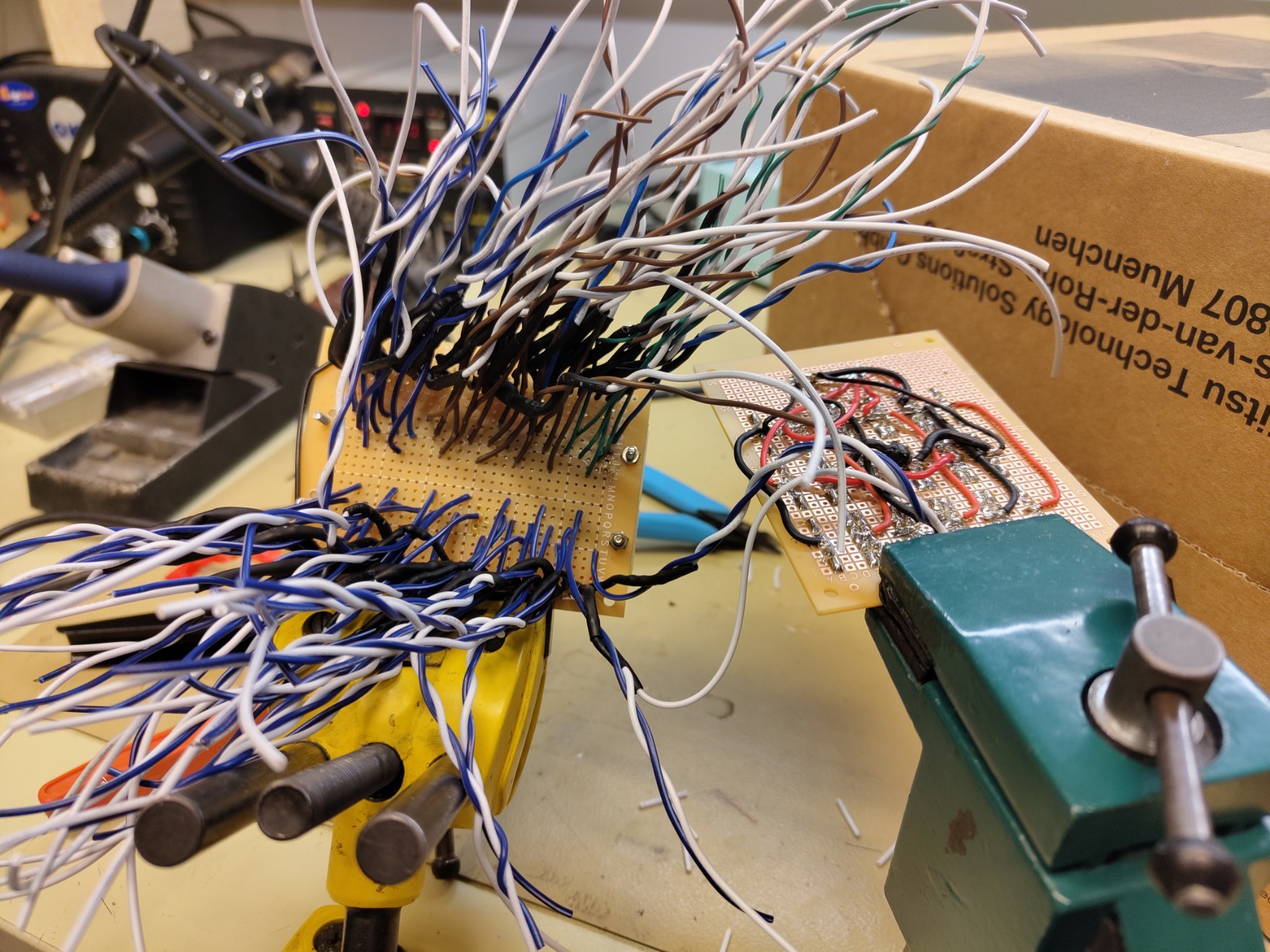
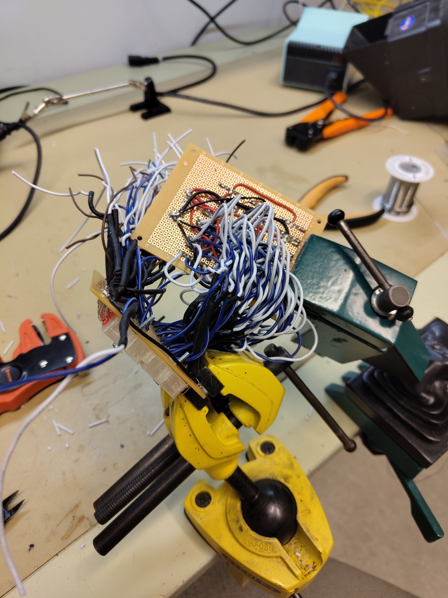
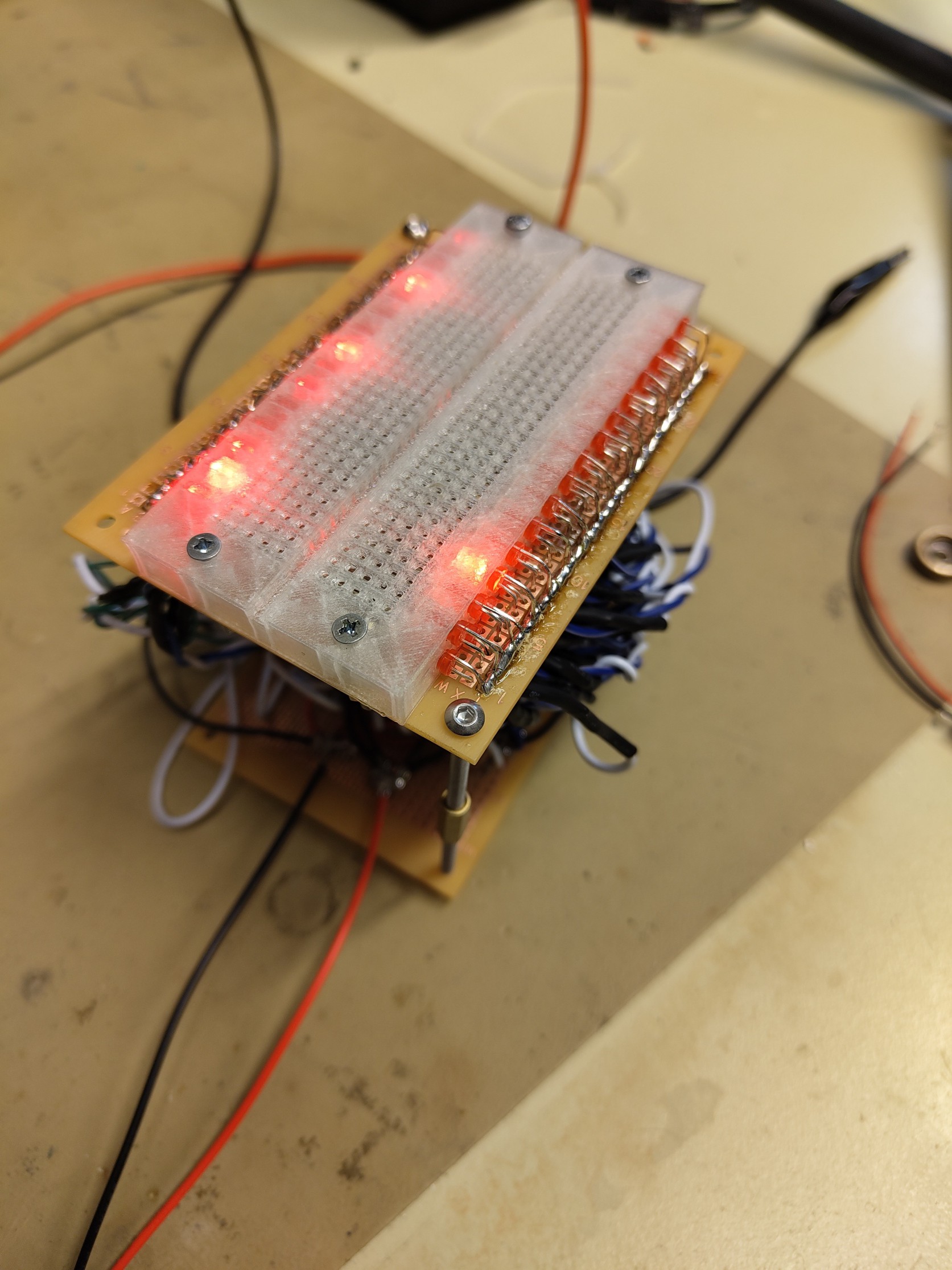
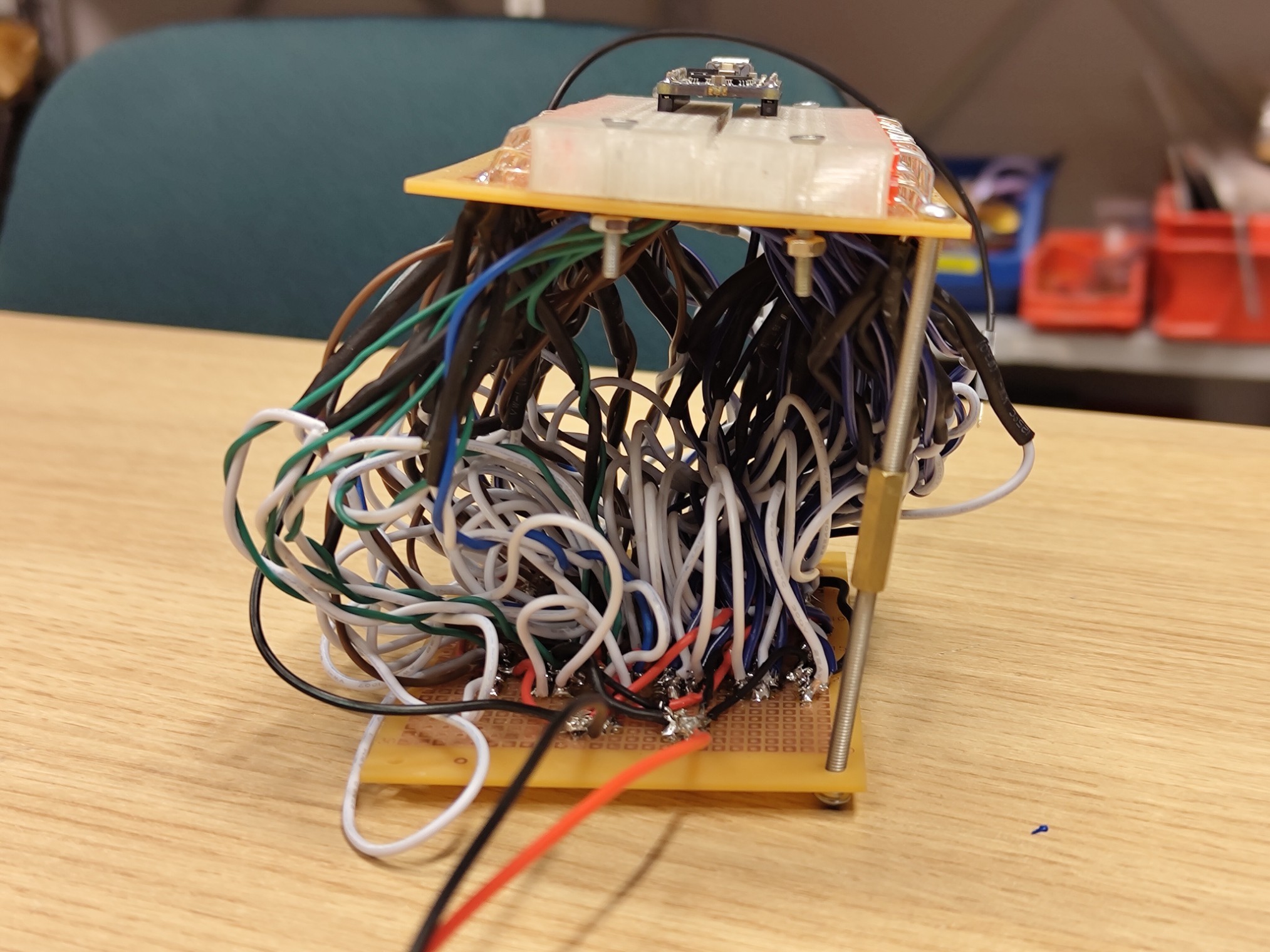
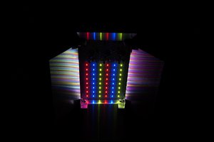
Lightup breadboard
Each line of the breadboard has an LED that glows based on the voltage on that line
Become a Hackaday.io member
Already have an account? Log in.
Just one more thing
To make the experience fit your profile, pick a username and tell us what interests you.
Pick an awesome username
hackaday.io/
Your profile's URL: hackaday.io/username. Max 25 alphanumeric characters.
Pick a few interests
Projects that share your interests
People that share your interests
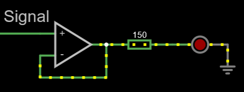 This simply will not do. An alternative to this was pitched with a separate voltage source for the LEDs from the OpAmps and a transistor but i asked around an got this
 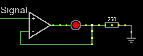 The OpAmp has enough oomph to supply the current.
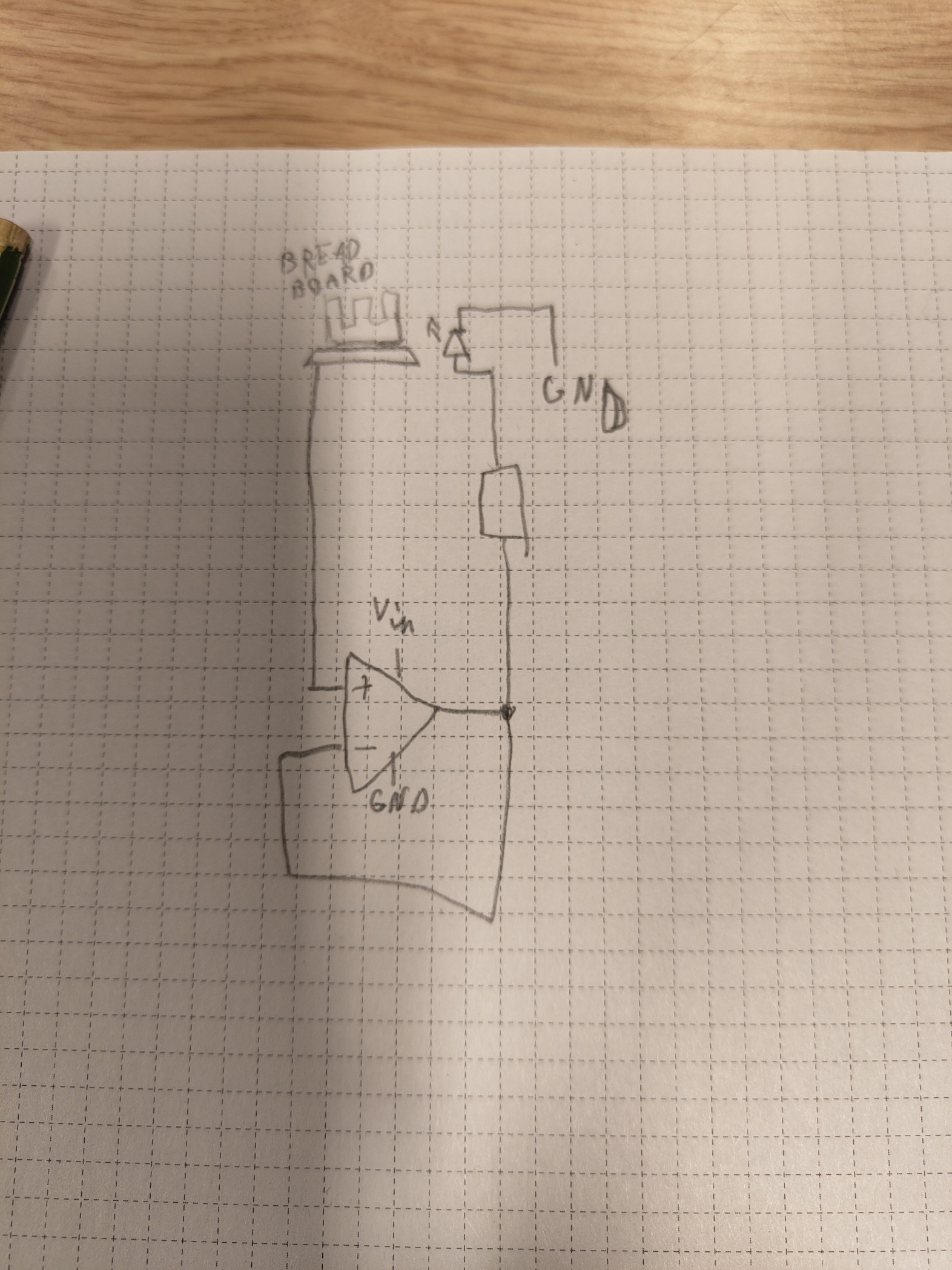


 t.oster92
 mmca
mmca
 zakqwy
 Yann Guidon / YGDES
Some suggestions for possible improvements - just what came to my mind, not implying you'd actually need to do any of this.
1. Drive the LEDs with a current source, so that their brightness will be linear in voltage. Right now, the LEDs are dark below about 1V, and their response is fairly nonlinear above that. all this takes is one extra transistor in addition to the resistor you already have, if you had a separate 12v supply for the LEDs. +12V to LED anode, LED cathode to NPN collector, opamp output to NPN base, top of current sense resistor to NPN emitter and to op-amp (-) terminal, bottom of current sense resistor to ground. The op-amps can run from 6V to accommodate 0-5v input range in this case. Yes, LEDs use 12V, op-amps use 6V, breadboard circuit can use any VCC between 0V and about 5.3V.
If the op-amps cannot run from 6V, then a diode from NPN base to op-amp output is needed, and a pull-up resistor on the NPN base up to 12V. 10k should be a good starting point. The diode shifts the base voltage about one diode-drop above the op-amp output voltage, removing most of the Vbe offset of the NPN transistor.
There are single-package biased Sziklai pairs (PNP "driver", NPN "output stage", and bias resistors) that would implement this level shifting with just one part in place of the NPN transistor - so pretty handy I'd say.
2. Drive the LEDs with a logarithmic current source, so that their brightness is proportional to the log of the voltage. This would require a monolithic diode array (e.g. https://electronics.stackexchange.com/questions/630272/can-uln2003-be-a-poor-man-s-matched-diode-array) so that one diode out of 7 could be used for an Imin voltage reference. Or use transistor pairs in single 6-pin SMT packages.
3. Drive RGB LEDs such that their color "walks up the rainbow" as the voltage goes from -Vref to +Vref. Vref could be adjustable based on the circuit you work on. This would take at least 2 op-amps per channel, and I'm not even sure that'd be enough. With 4 op-amps per channel you'd have plenty of room to work with.
4. Drive a two-color LED, so that one color lights up for negative voltages, another for positive voltages. E.g. a red + green LED, with both being on - for a faint yellow light - within some neighborhood of 0V. The width of this neighborhood could be adjustable down to 0 as needed.
5. Consider adjustment of both -Vref, 0Vref, and +Vref. For example, for digital logic, -Vref would be 0V, 0Vref would be Vcc/2, and +Vref would be Vcc.
Many other tweaks are possible of course. This seems like a cool idea that can be expanded a lot. I really like this - visualizing breadboard operation in such a way is pretty simple yet useful.