 Kris Winer
Where we started
Ever since I first learned how to use my beloved 8 MHz Arduino Pro Mini with the Arduino IDE I have pined to move up to the more powerful STM32F4 with its faster CPU clock, floating point engine, and rich peripherals. I bought STM32F4 Nucleo and Development boards and used mbed to program them but this was a very frustrating experience. mbed is sufficiently different from the simplicity of Arduino that I literally had to completely rewrite my sketches just to get them to compile. I don't know how many times I tried to use adult tool chains like Keil and gcc/eclipse to program these powerful MCUs but I never even got past the installation process getting stuck somewhere in the complicated series of steps to download and install various parts of the tool chain. I took several ST-sponsored training classes to learn how to use ST-Link and the STCubeMX system with the Keil and IAR tool chains to blink leds and read sensors. But when I tried to use the STM32 development boards at home I could never get them to work. Frustration maximized, I turned to the Teensy 3.1 for my projects and rejoiced in the ease of Arduino programming via the USB and forgot about the STM32 for a while.
When ST released the first STM32L4 MCUs my interest was rekindled. Here was offered the performance of the STM32F4 with a floating point engine plus the low power consumption demanded by many of my battery-powered wearable and remote logging projects. I immediately designed a development board for the STM32L476 and tried to program it using ST-Link and STCubeMX after taking yet another ST class on how to program the STM32L4. I couldn't make it work, but fortunately for me Thomas Roell noticed my design on the shared space at OSH Park and asked to collaborate on improving it. There and then our deal was struck: I would design and build the hardware, he would design and build an Arduino core and we would both test and use what has become one of the highest performance MCUs available to the Arduino community.
We started on Tindie with Dragonfly, an STM32L476 using the 10 mm x 10 mm LQFP64 package, with 16 MByte QSPI flash on board, a supercap for RTC battery backup, an rgb led, 16 MHz and 32.768 kHz crystals, and all GPIOs exposed to the user including the SWD port for those who might want to use a ST-Link to program the board the old-fashioned way. What a delight to have access to an 80 MHz MCU with FPU including five serial ports, three SPI ports (or two plus an I2S port), three I2C ports, one CAN port, thirteen PWM-compatible pins, and two separate DACs, all programmable through the USB using an Arduino IDE and standard Arduino APIs. It was like having a Teensy 3.1 on steroids!
Where we are now
We realized that not everybody needed the extra hardware and peripherals that were included with Dragonfly. So now we would like to extend the Dragonfly family to make use of the latest STM32L4 MCUs that come in smaller and more cost-friendly packages; Butterfly with the STM32L433 and Ladybug using the STM32L432.
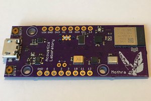
Butterfly (0.7" x 1.4") and Ladybug (0.6" x 1.1") are small, low-cost development boards with simple, open-source designs that will allow just about anyone to make use of the STM32L4 in their own custom applications. They rely on a single, inexpensive 32.768 kHz crystal oscillator and don't require the ST-Link built in to the STM32 Nucleo boards. Applications can be developed using the Butterfly and Ladybug development boards which provide access to all GPIOs and peripherals of the STM32L4. When the application has been sufficiently proved out, application-specific hardware can be designed using the STM32L43X development board as a design template. The 7 mm x 7 mm QFN48 and 5 mm x 5 mm QFN32 packages of the STM32L433 (Butterfly) and STM32L432 (Ladybug), respectively, are space-efficient, low-cost but still powerful solutions to embedded computational and sensor management problems. Better still,...
Read more »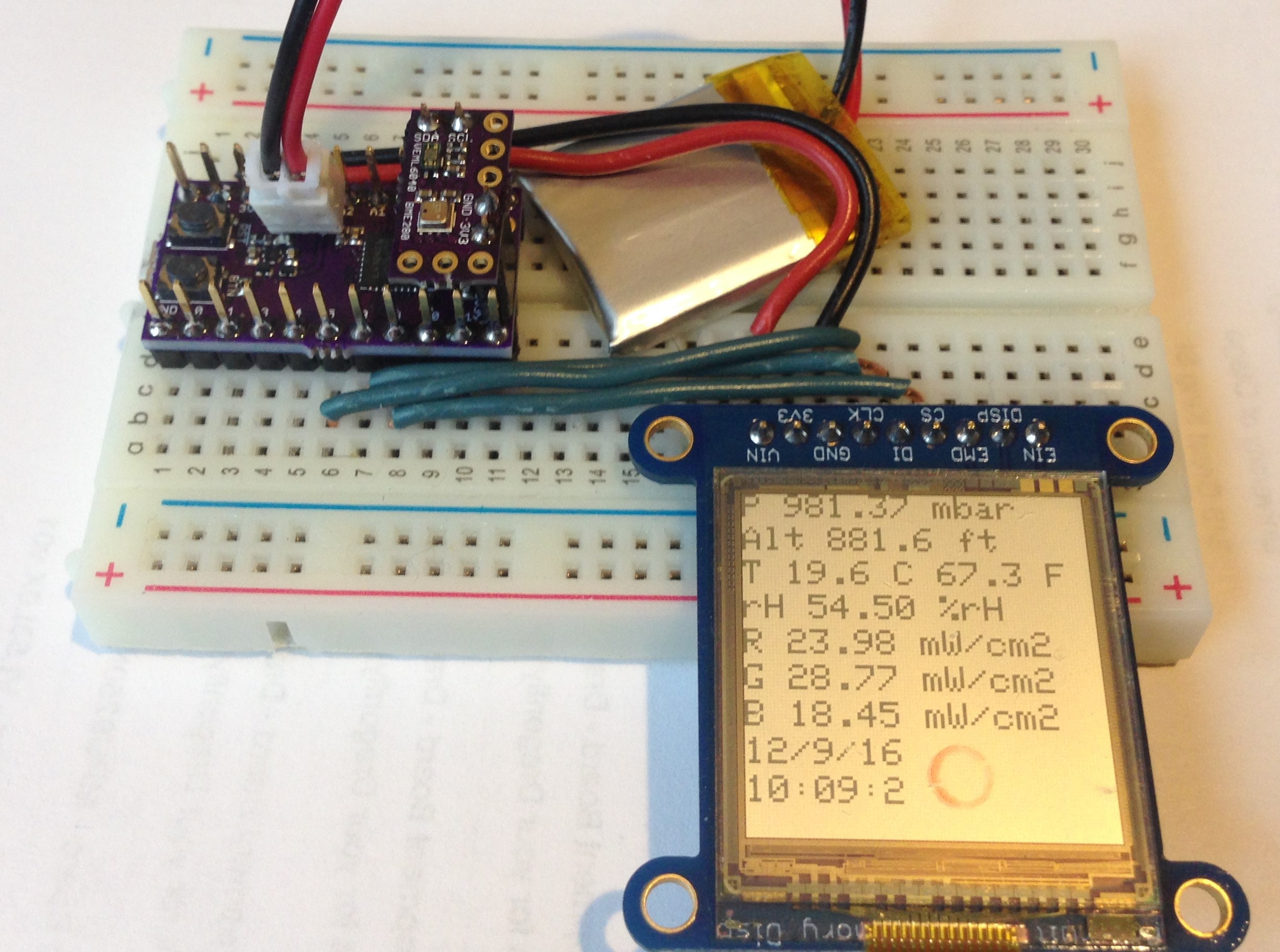


 James Cannan
 Open Green Energy
I have used the fft analyzer in the ArduinoSound library and it works fine, but I am a bit disappointed in the broadening of the normal modes it produces. This might be due to improper configuration on my part. But the worst problem is that the size of the code using this library is enormous because of the giant lookup tables they use or something, not sure. If you get the fft to work on your Butterfly and the performance and code size are reasonable, I would sure like to make use of it for my self. So when the time comes I hope you will share it wth me!
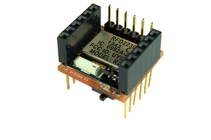
We are in the process of making ESP8285 wifi add ons available for Ladybug and Butterfly (next week or so) and we are designing a BLE add-on also (nRF52) that can be configured completely from the Arduino sketch on the STM32L43X side. This will be available in a month or two. Lastly we will also add a LoRa radio add-on and/or a LoRa development board using the Murata STM32L0+LoRa radio module. This latter is still in the design stage but we want to have a cheap and convenient wifi, BLE, and LoRa radio solution available for these dev boards.