 CriptasticHacker
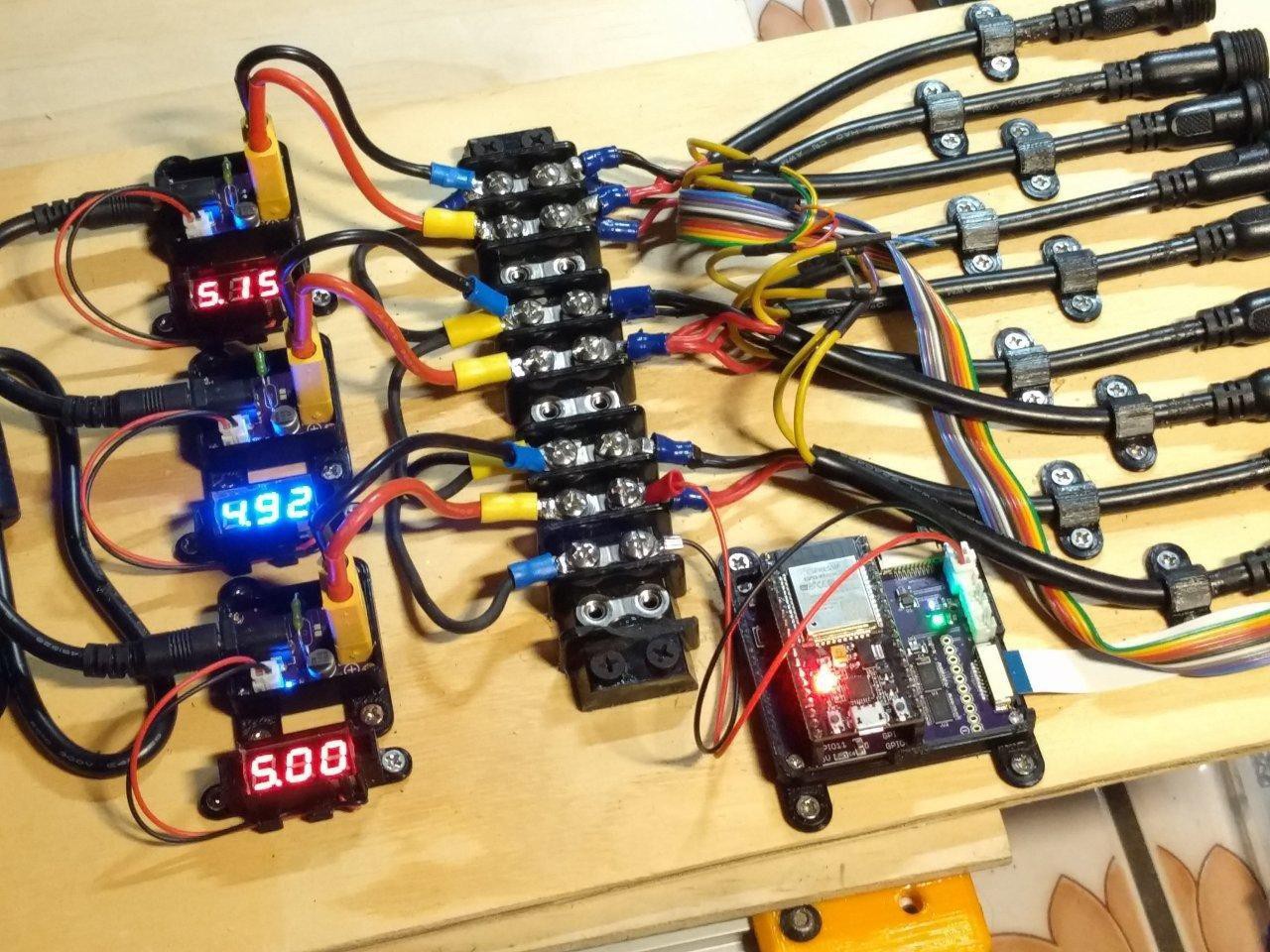
This display is powered by a wifi-controlled ESP32 WEMOS module. The specific breakout kit I inherited was a NodeMCU 32-bit module.
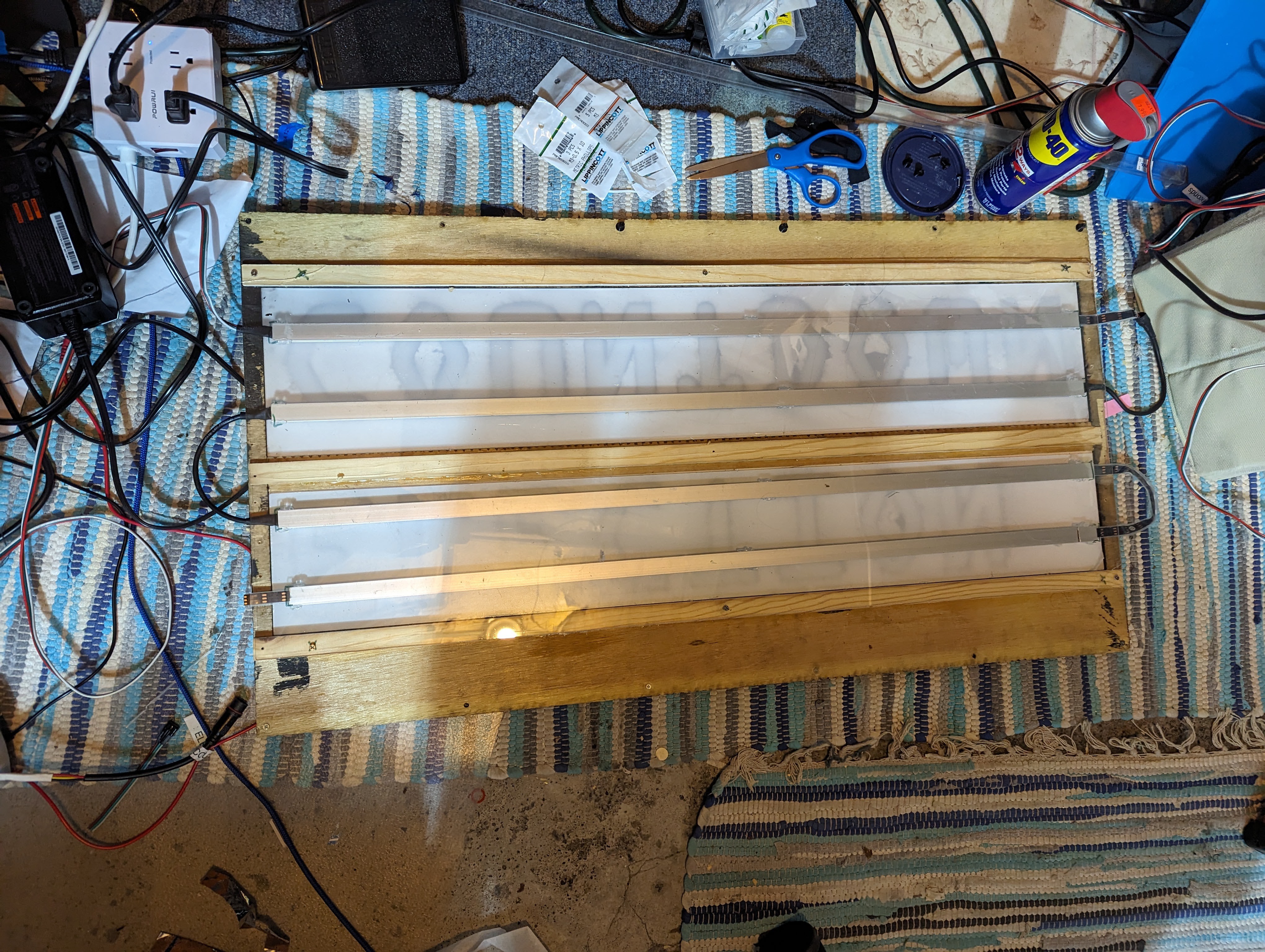
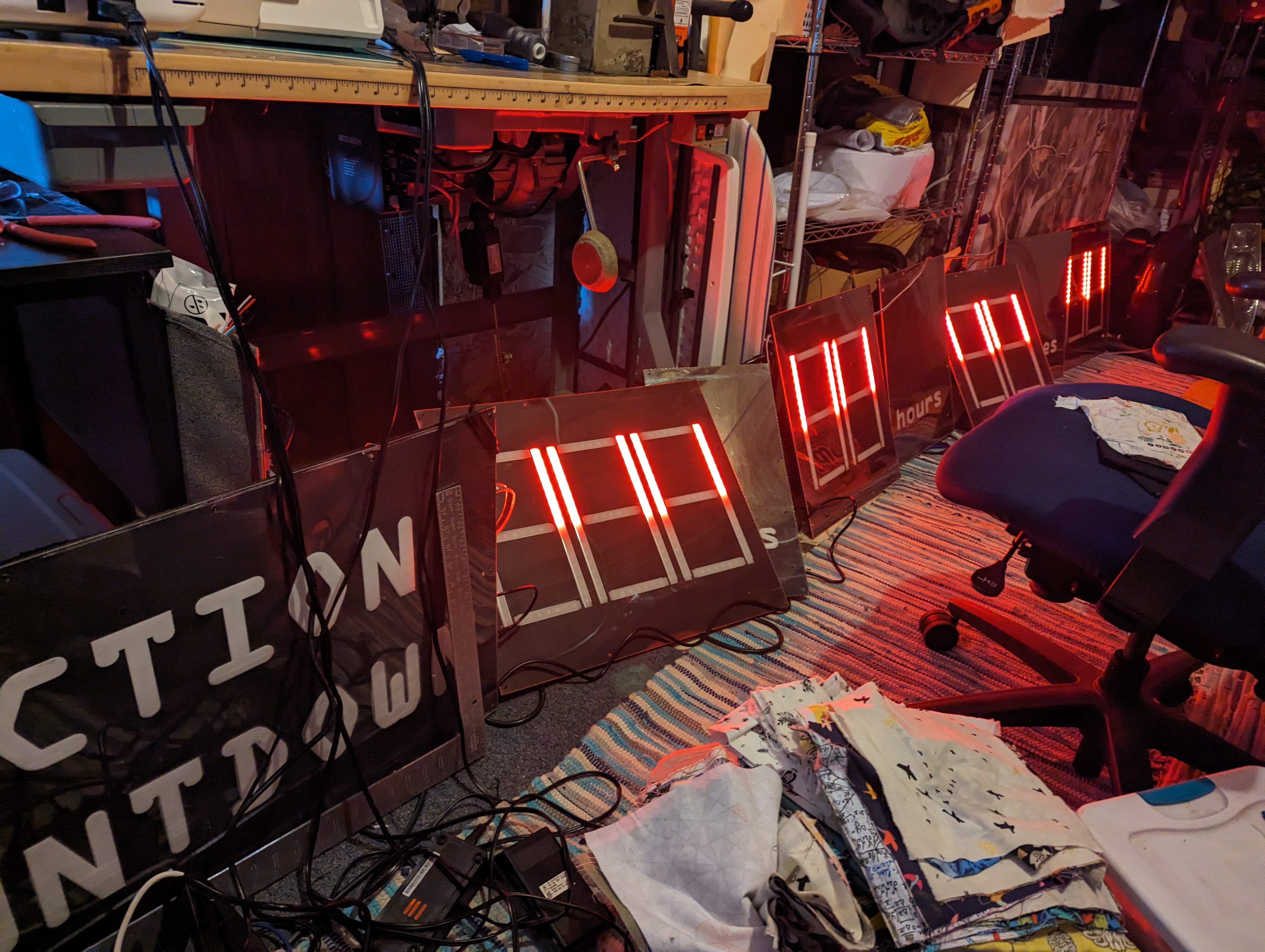
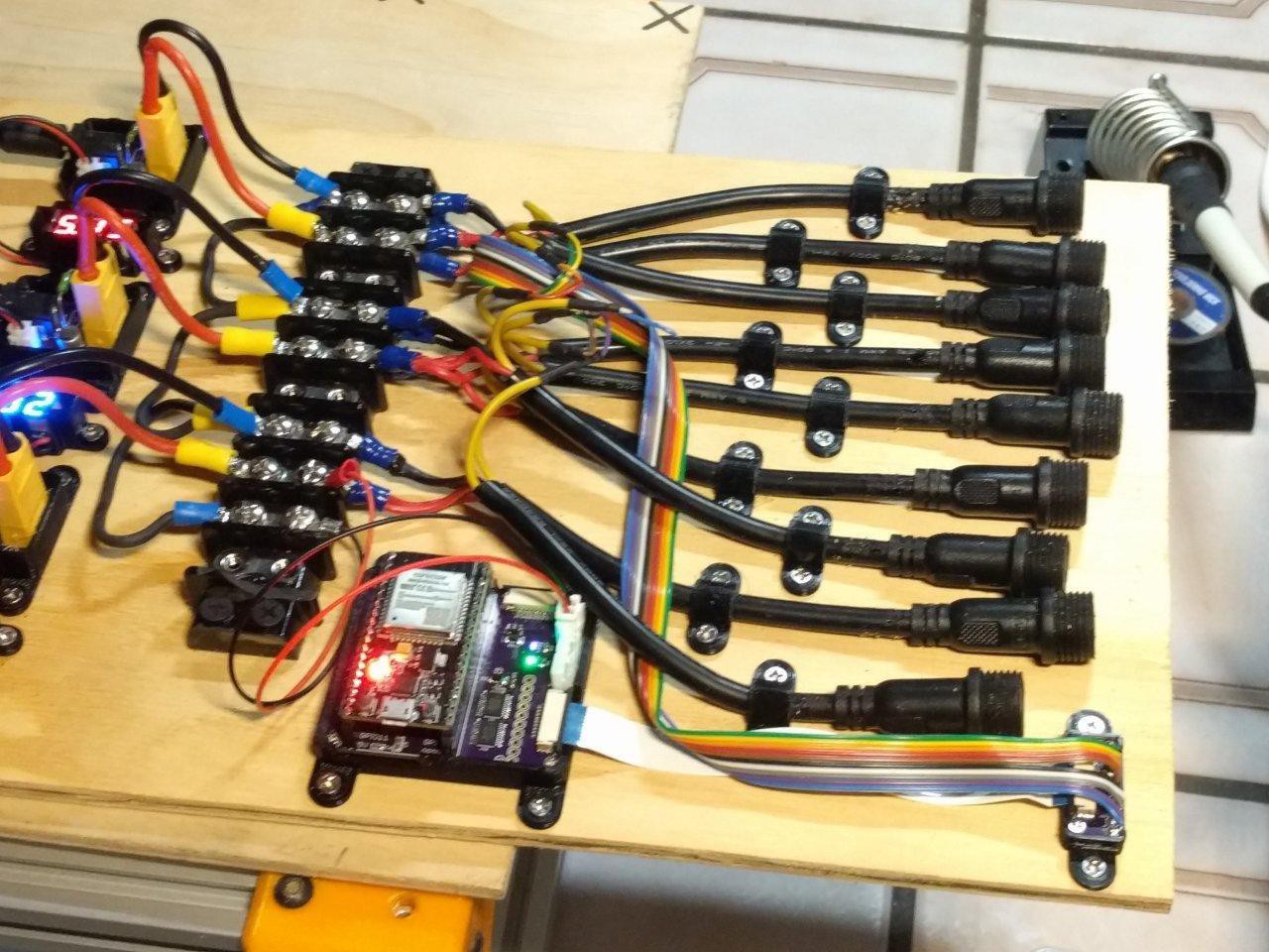
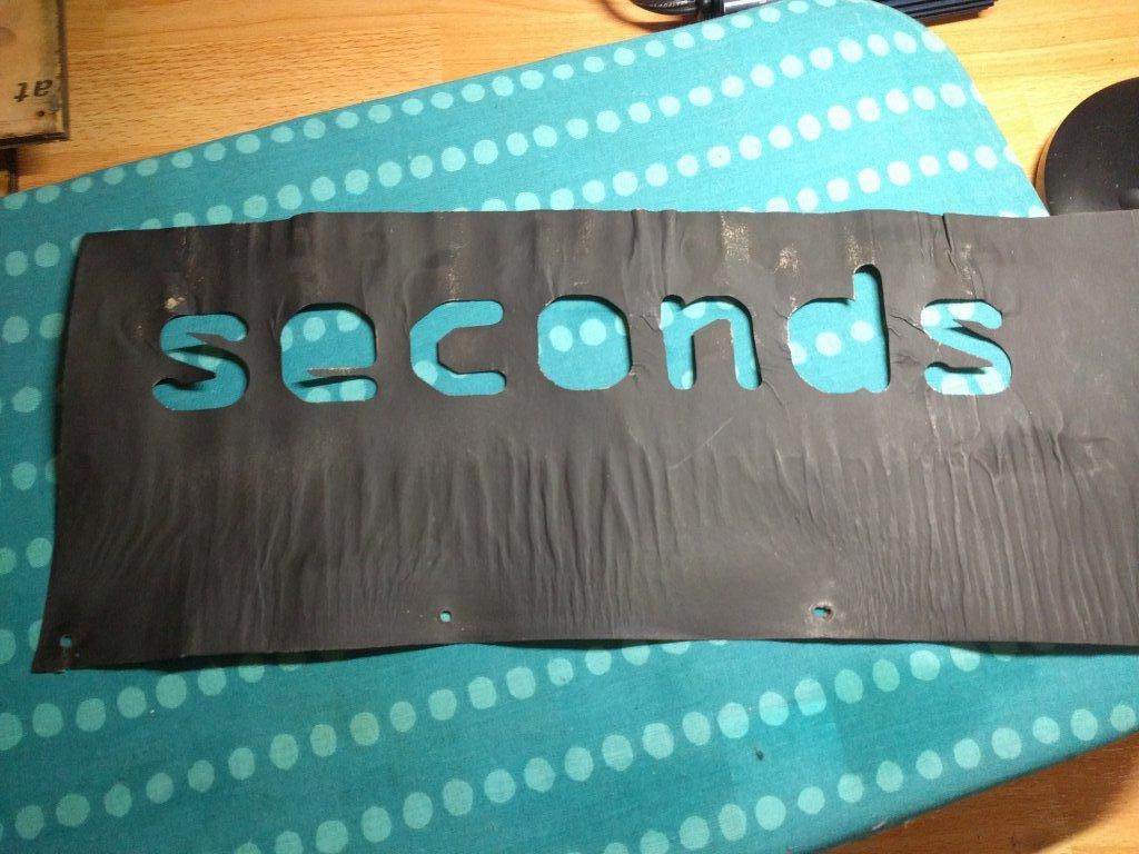
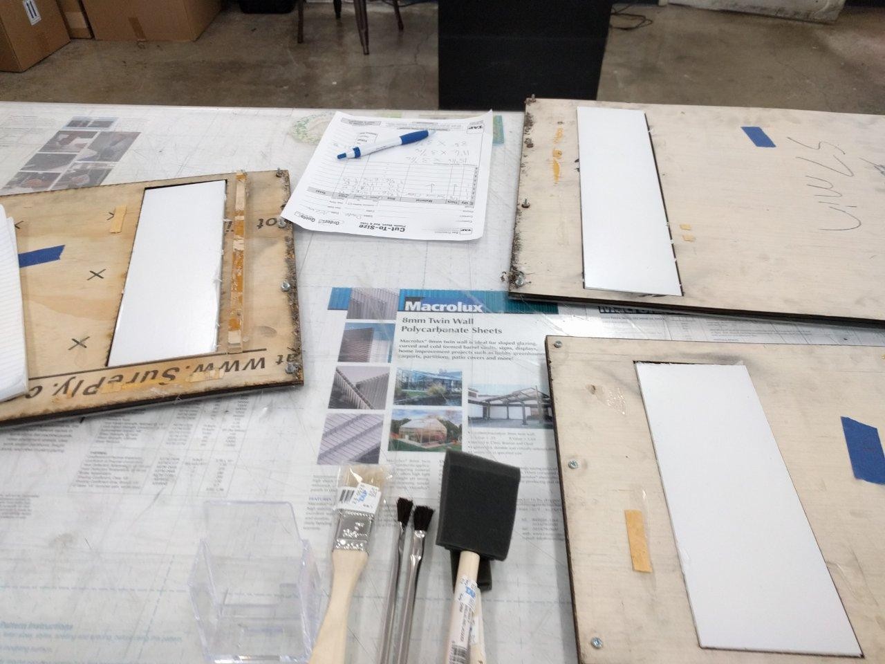
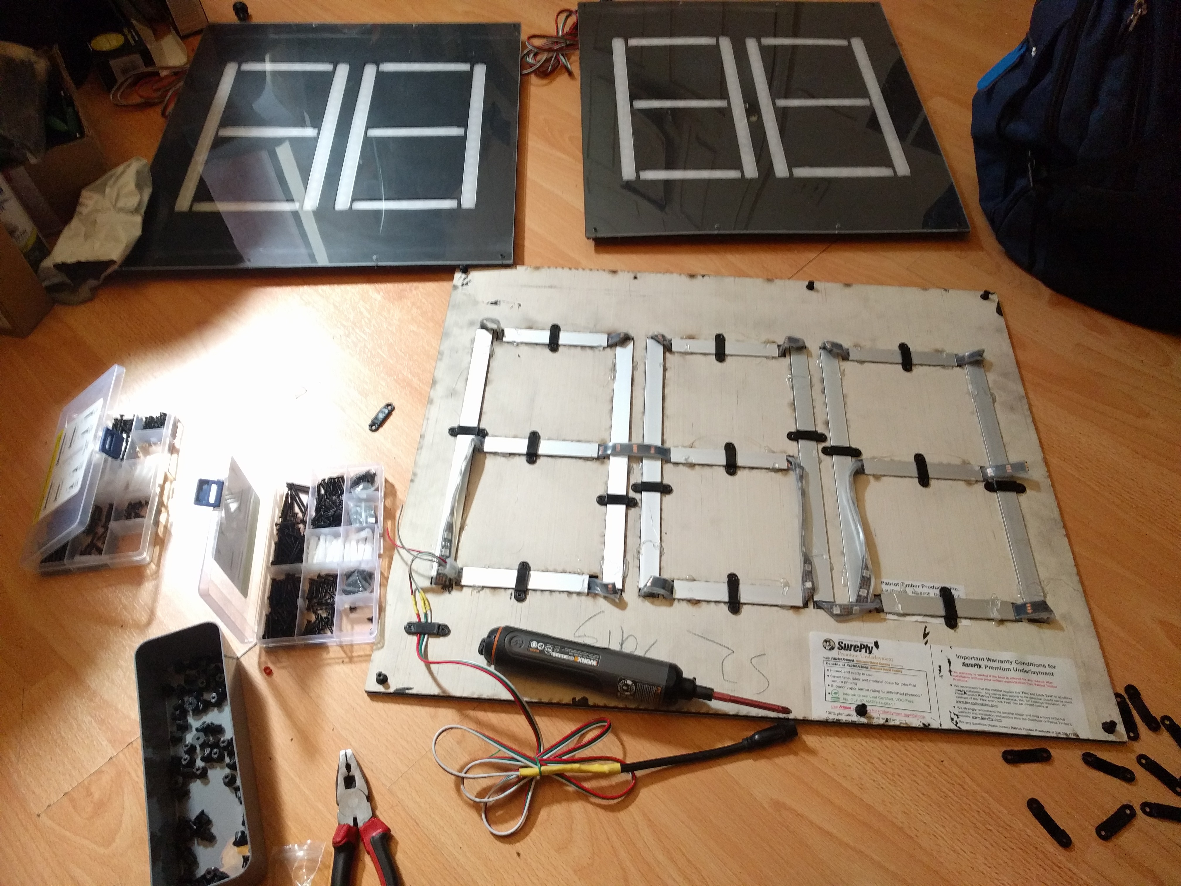
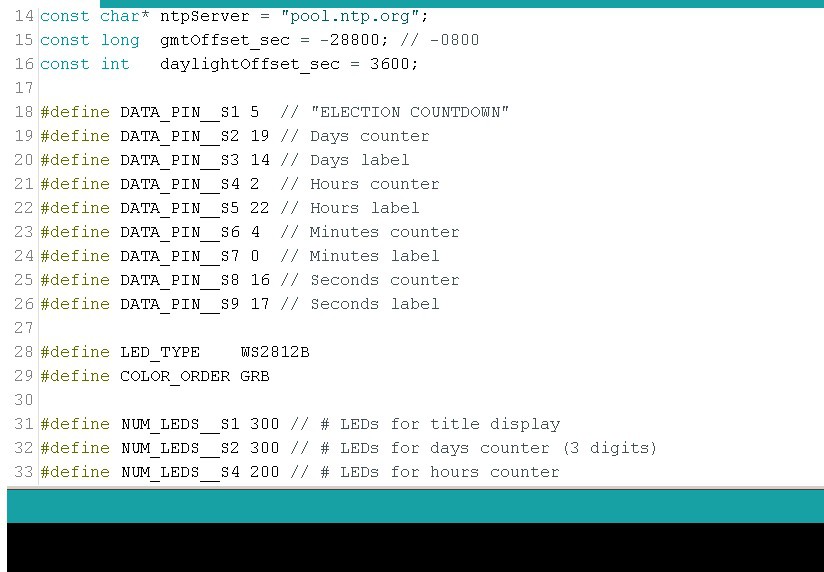
There are 9x panels in total (or so I'm told, I only 1x on hand) with 9 seperate control signals.
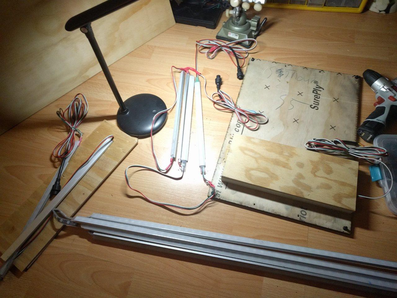
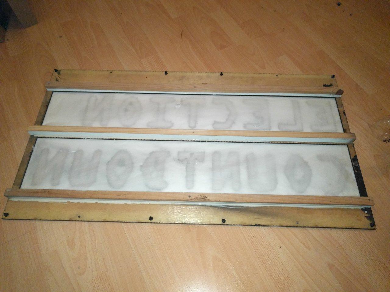
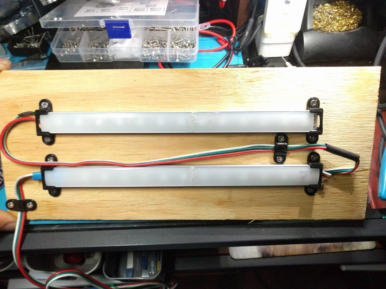
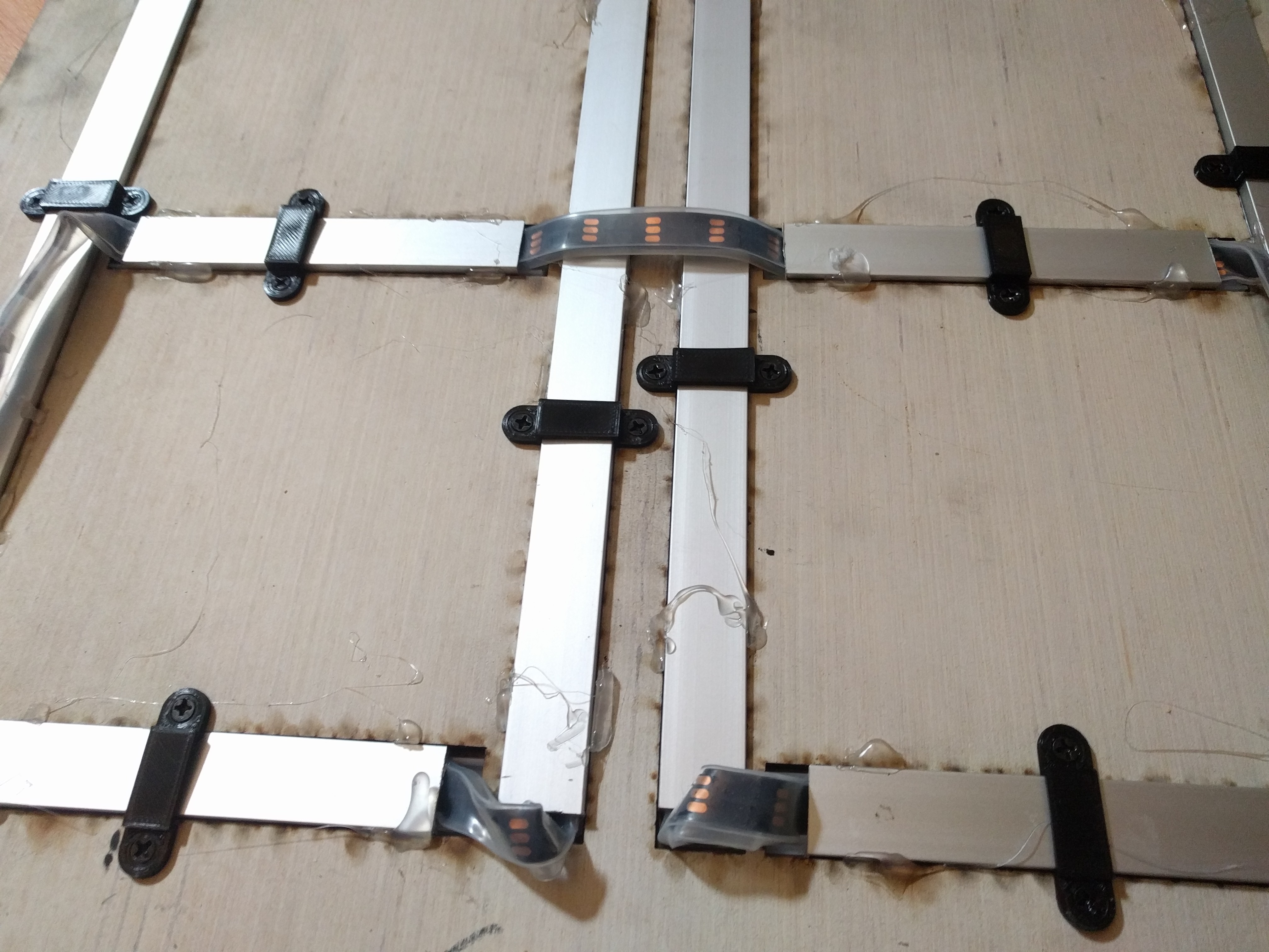
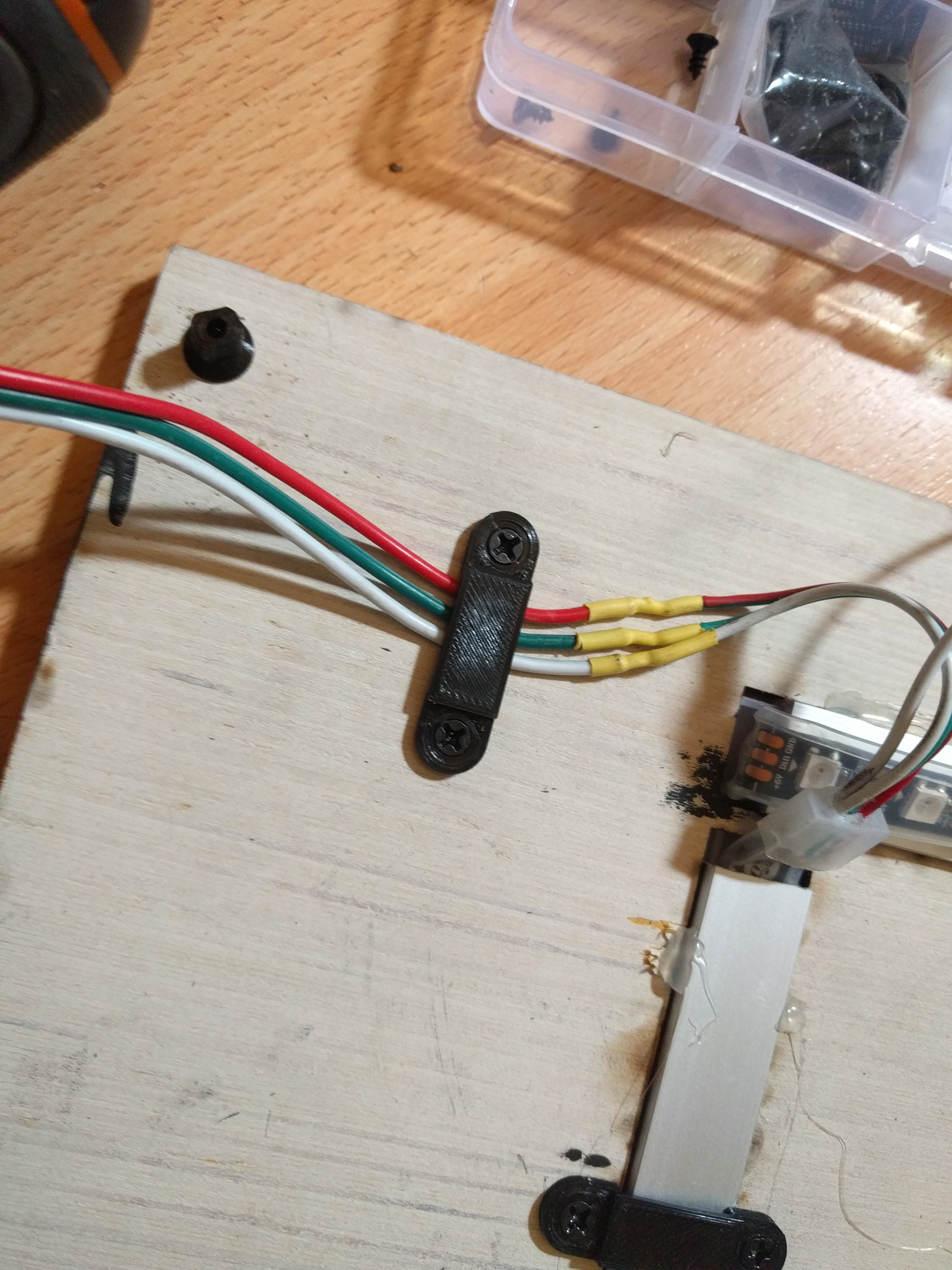
The panels all use the popular WS2812 "intelligent" LED (chip-based) strips.
These LED's have their own timing specific 1-wire interface, that is sadly not UART.
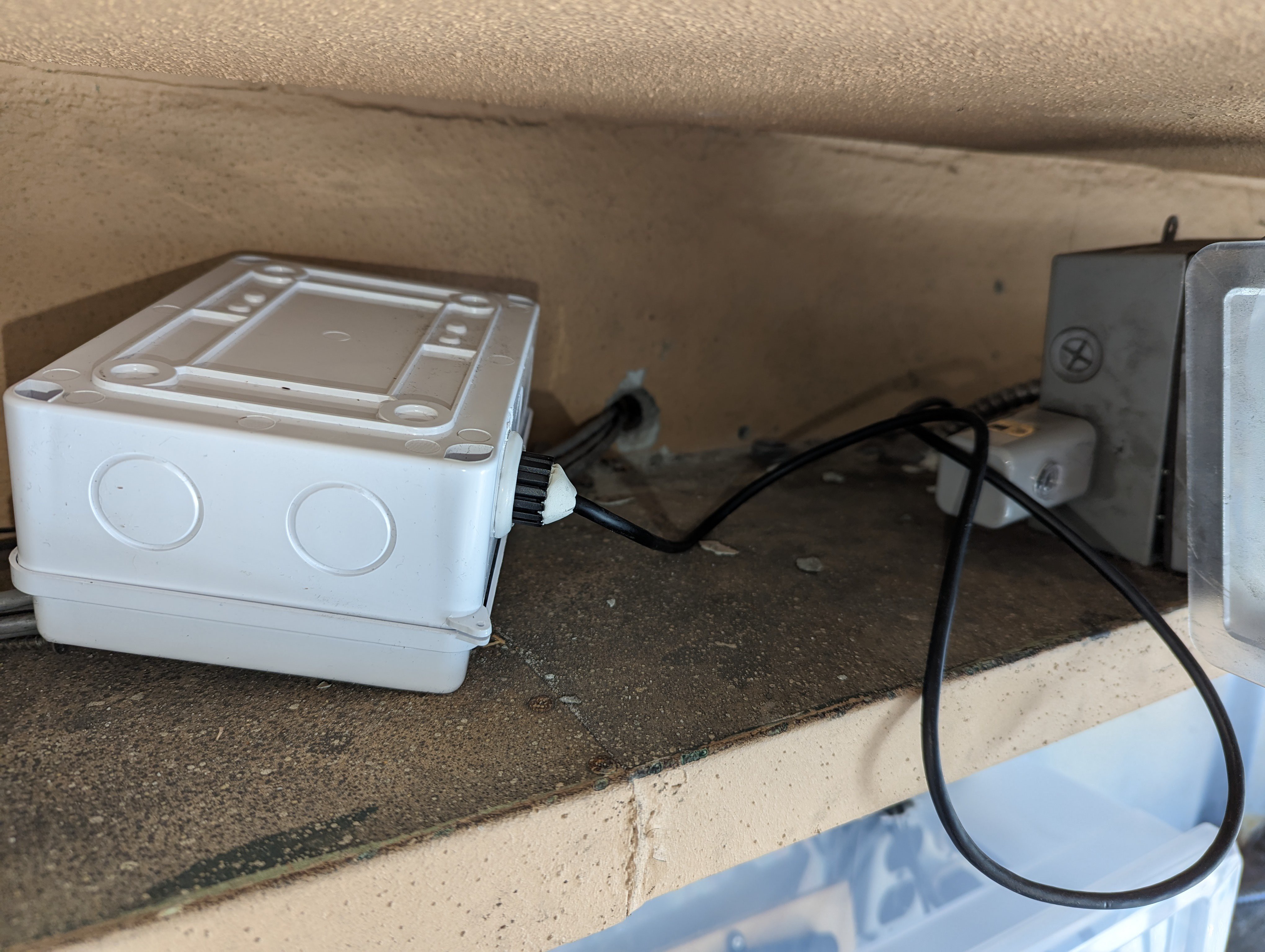
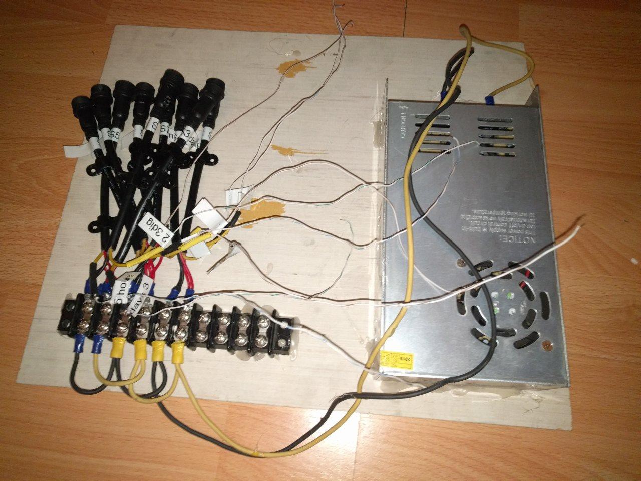
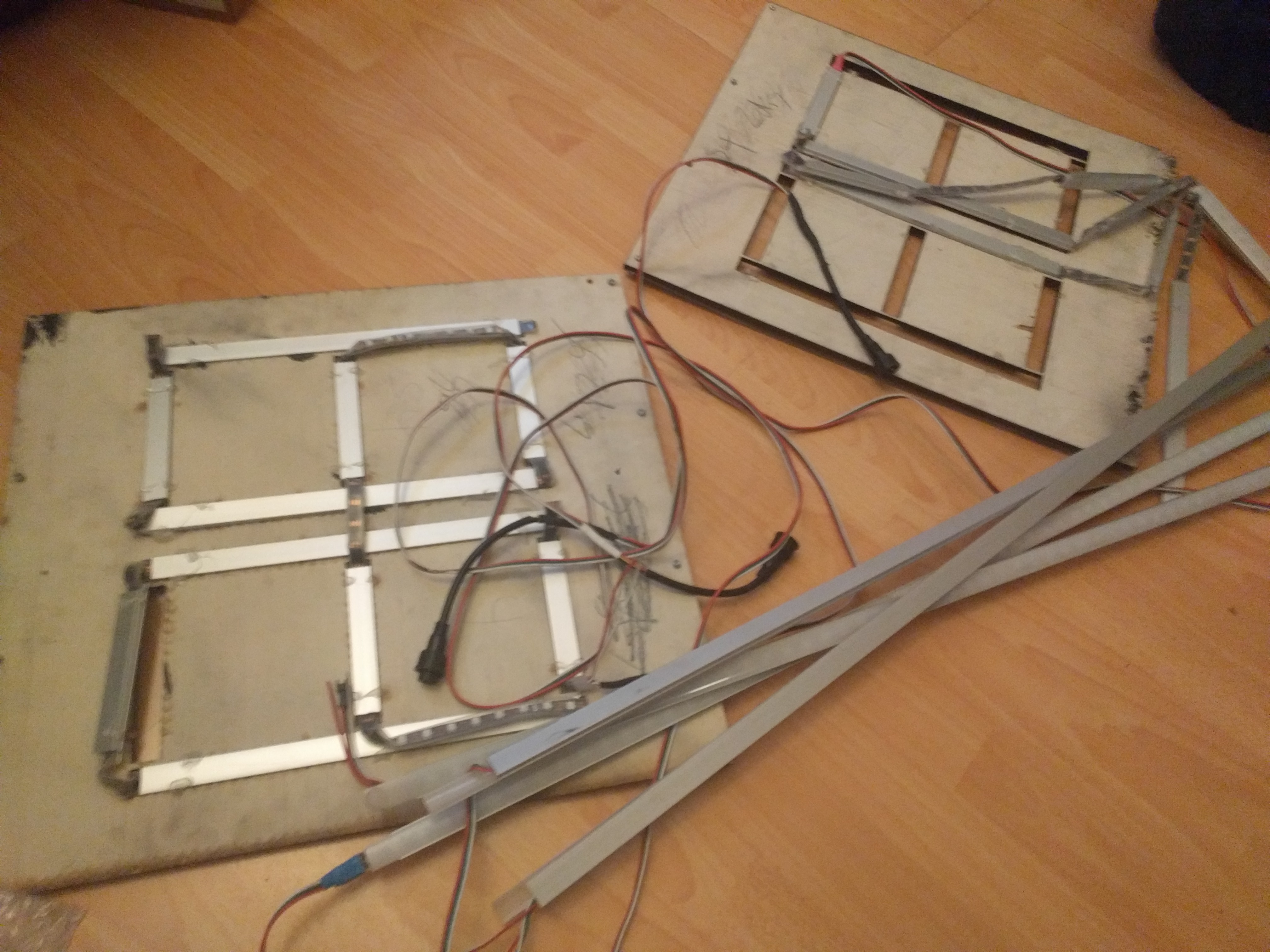
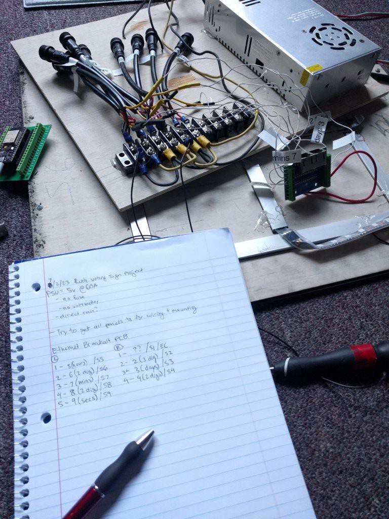
The power board looks like MDF plywood with lots of hot glue, a power supply, breakout screw terminals, and some (nice) weatherproof terminal sockets. Unfortunately, this is just about the only thing properly weatherproof-ed.
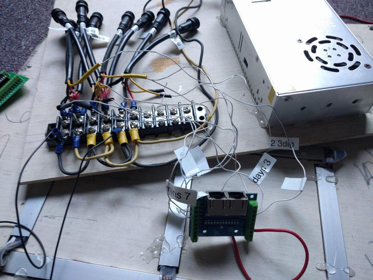
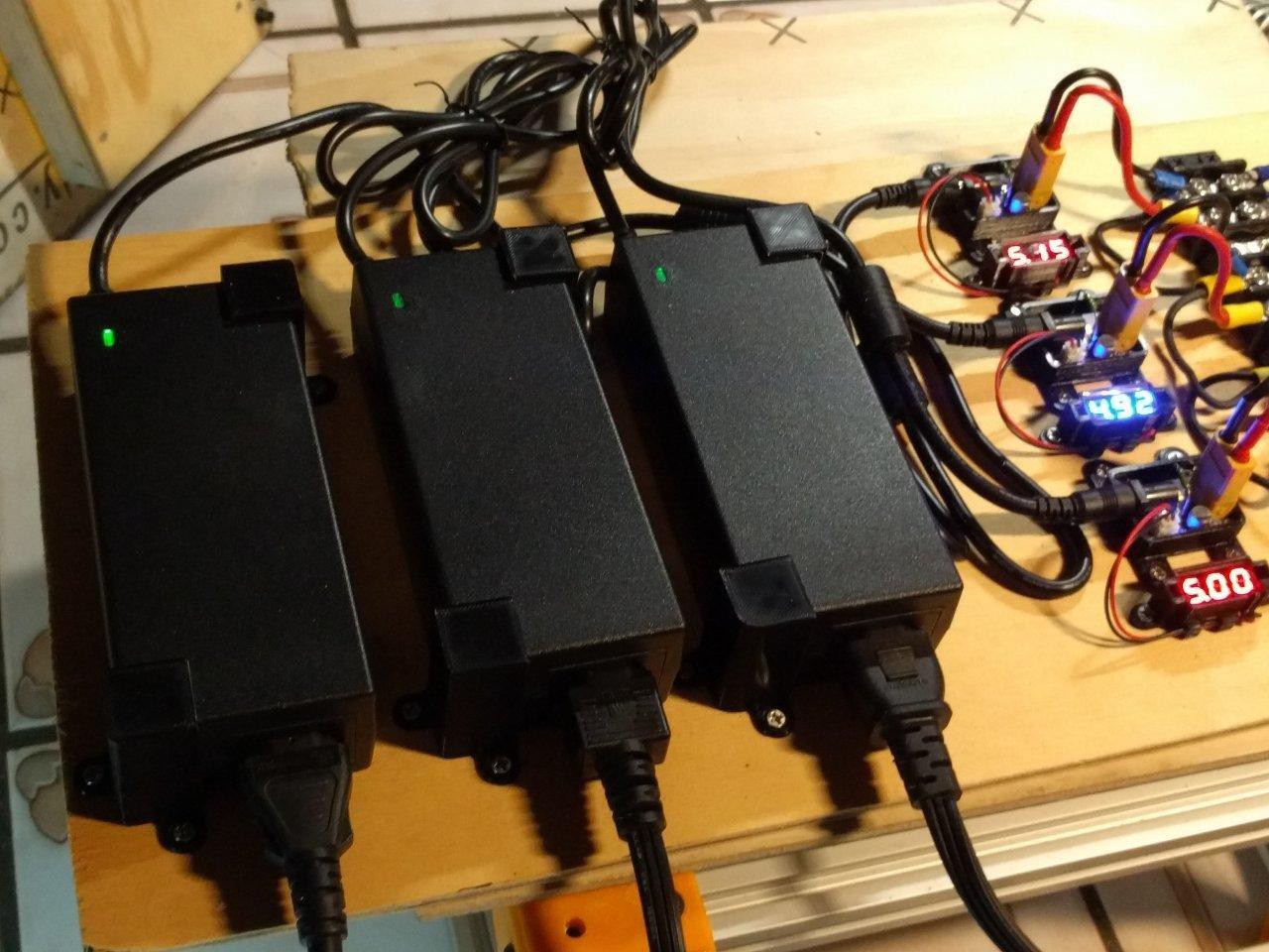
* The power supply is rated 5V @60A. It has no external fuse, and an open frame design, not suitable for weatherproof. There is a soldered glass fuse inside, but that doesn't offer much comfort. There is also one of those super cheap pots for adjusting output voltage. It needs to be replaced with an enclosed and safe PSU. Bonus points for having an on/off switch, pluggable AC, and a replaceable fuse.
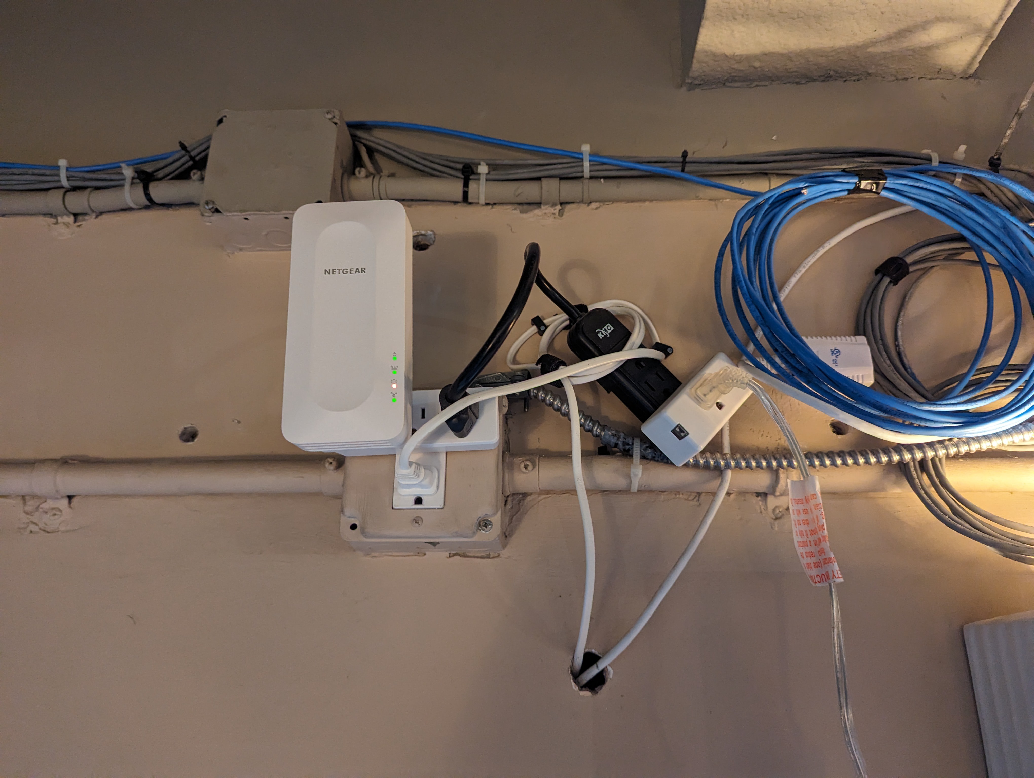
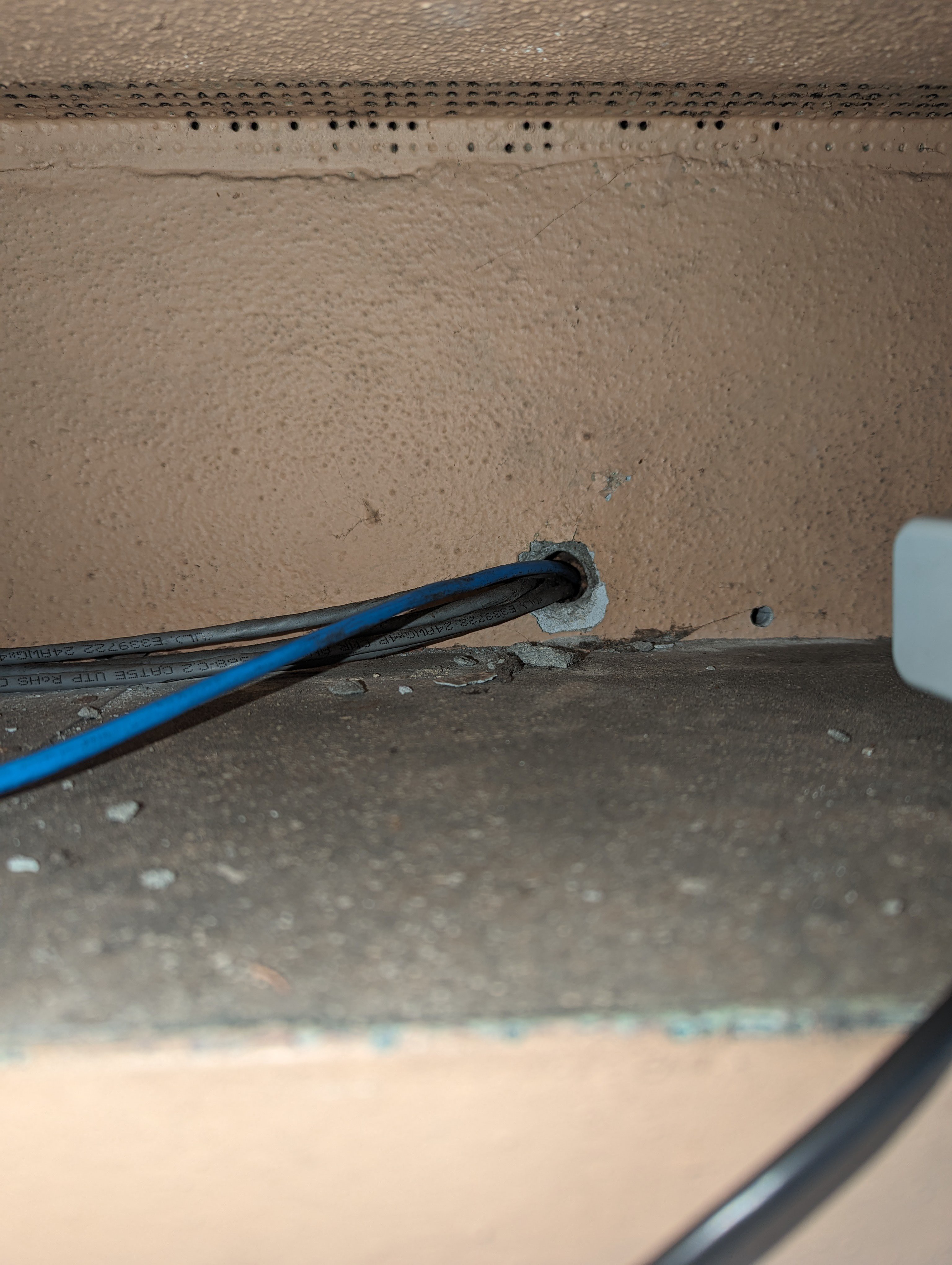
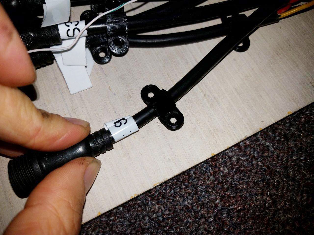
*Due to wifi proximity issues, the MCU output to the LEDs is distrubted through an ethernet cable, that way the ESP32 can live inside somewhere near the router and run the ethernet to the outdoor panels. I'm not a huge fan of this, especially if the cable is going to be many feet long, due to the 1-wire fast pulses of the LED chip controllers. Strongly considering adding a clock buffer to sharpen the rise/fall edges for accurate reads.
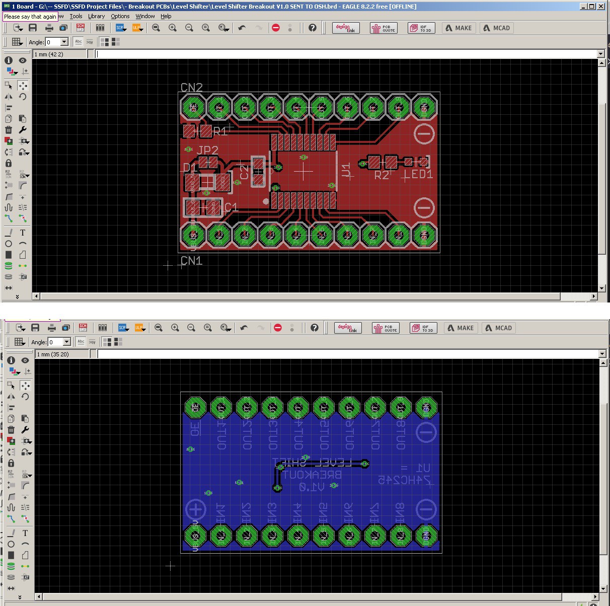
*The system needs a 3.3v --> 5v level shifter.
Nothing too complicated there, although doing this within spec does offer some considerations. For exmaple, a 74HC245 is an obvious choice. But the datasheet shows a logic high detection of 3.15V when VCC = 4.5V.
Since we're trying to power this off a 5V system, this could pose a real problem sending 3.3V signals that it might not actually register. An easy solution to this could be a series diode on the VCC line to regular the level shifter closer to that 4.5V range.
*There are coding issues. I don't currently have the latest working firmware, and what exists here utilized a lot of delay() functions instead of millis(). Most importantly though, the configuration of GPIO pins does not seem to consider startup condition issues that ESP32's have. I likely need to change them, assuming there is no special pin functions being used.
[to be continued...]
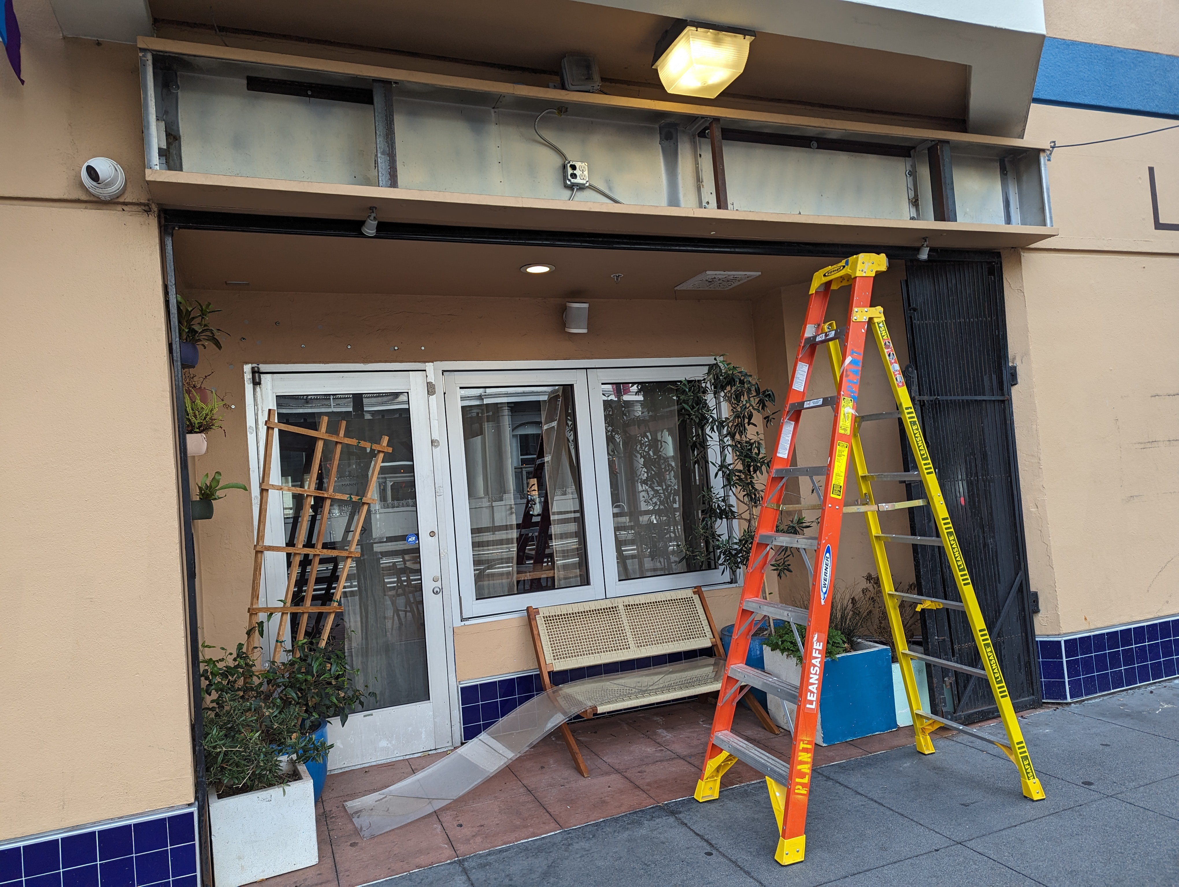
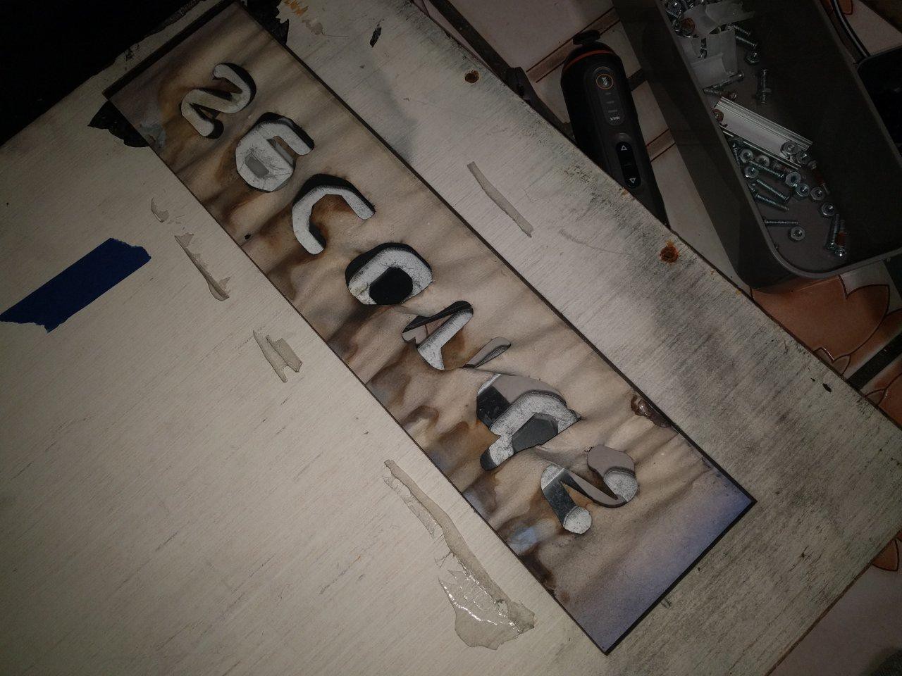
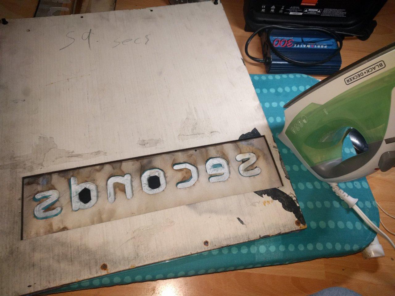
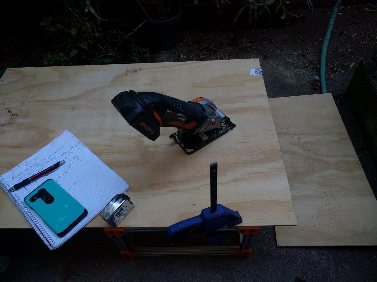
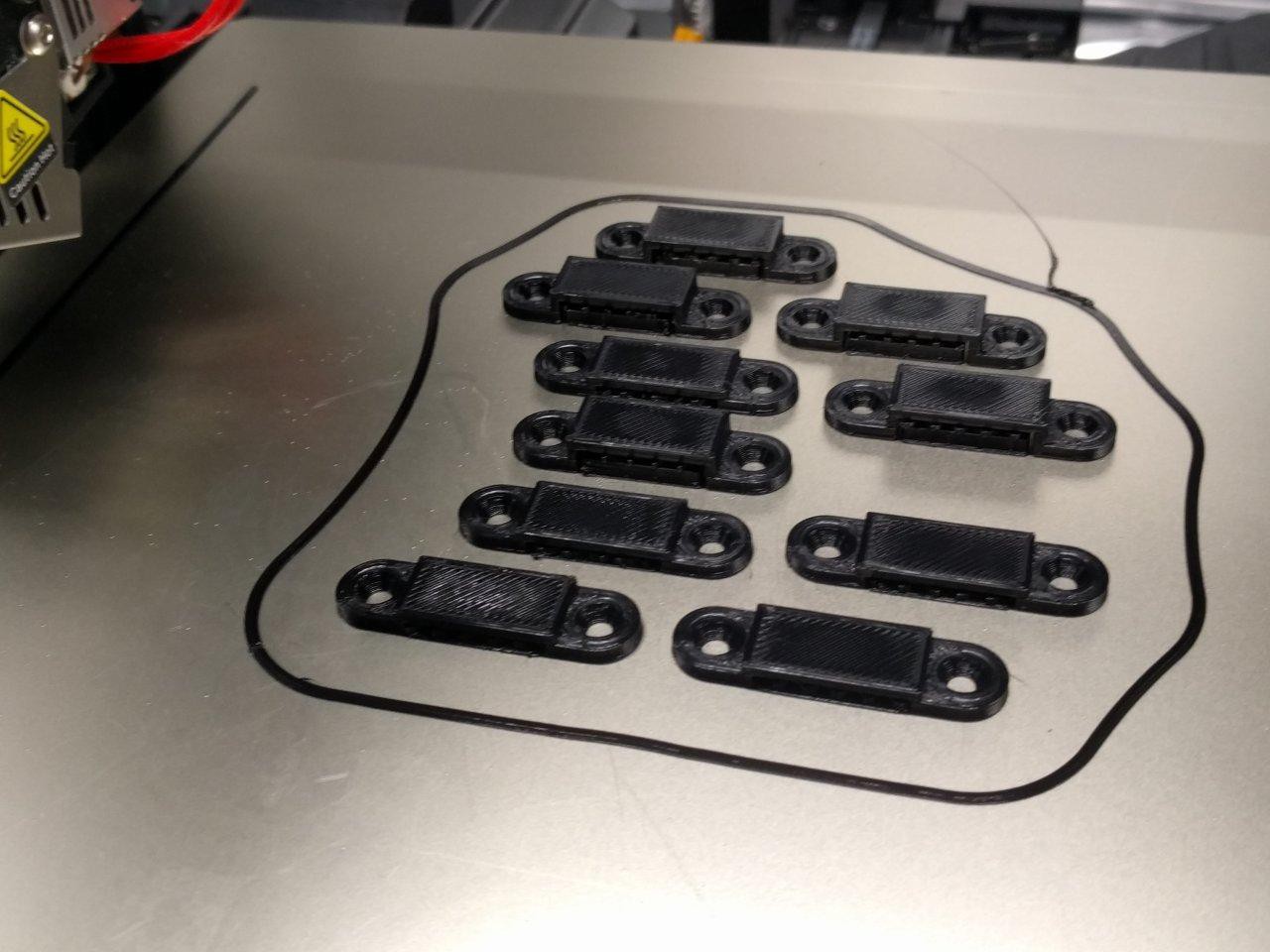
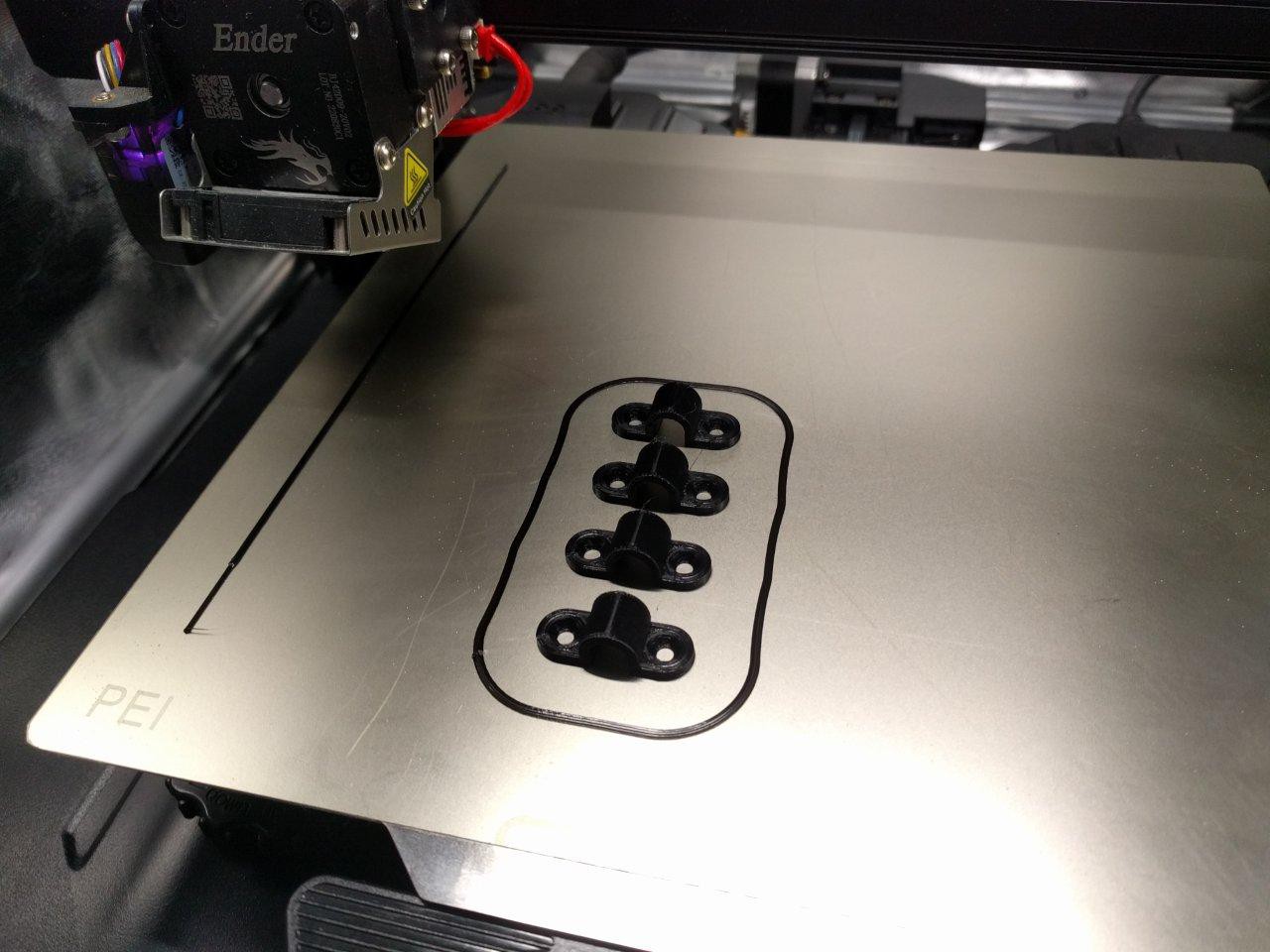
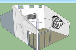
 Finally it was time to start installing the panels!
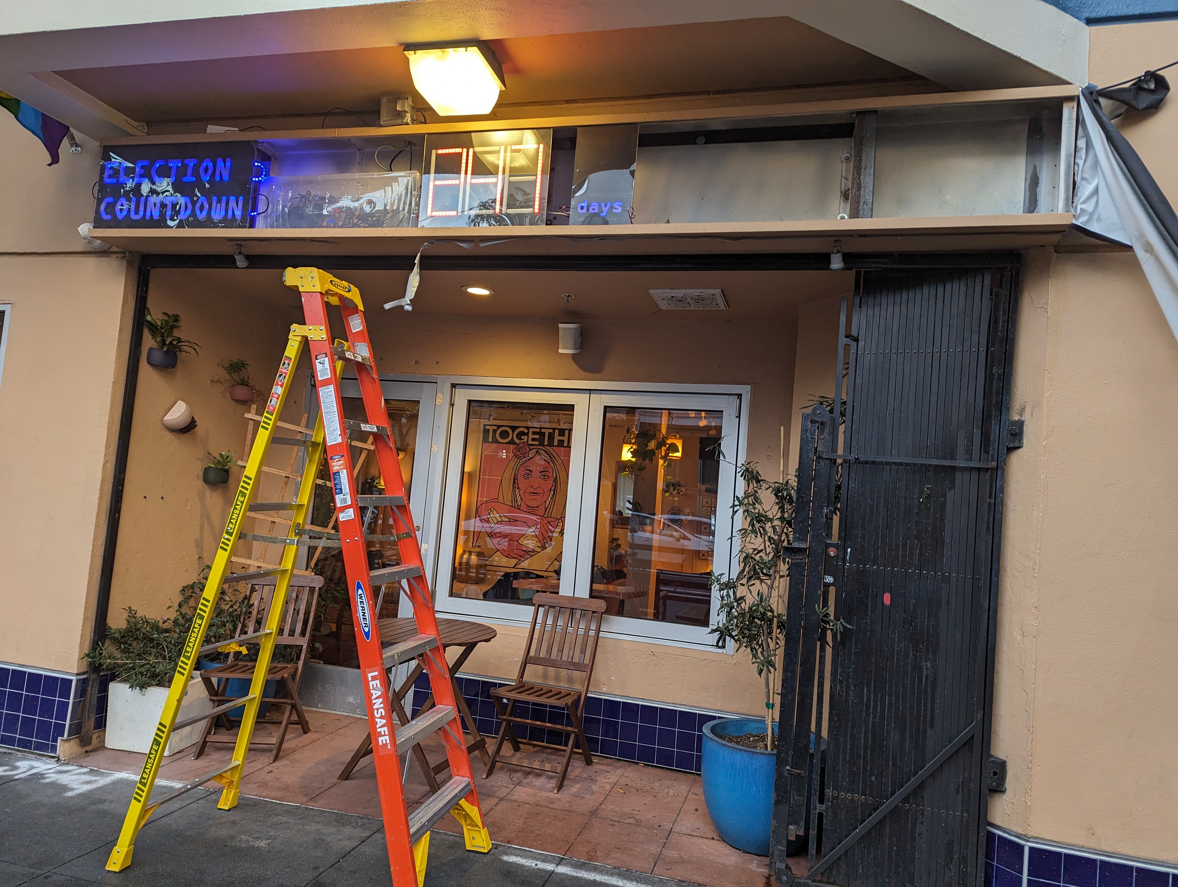


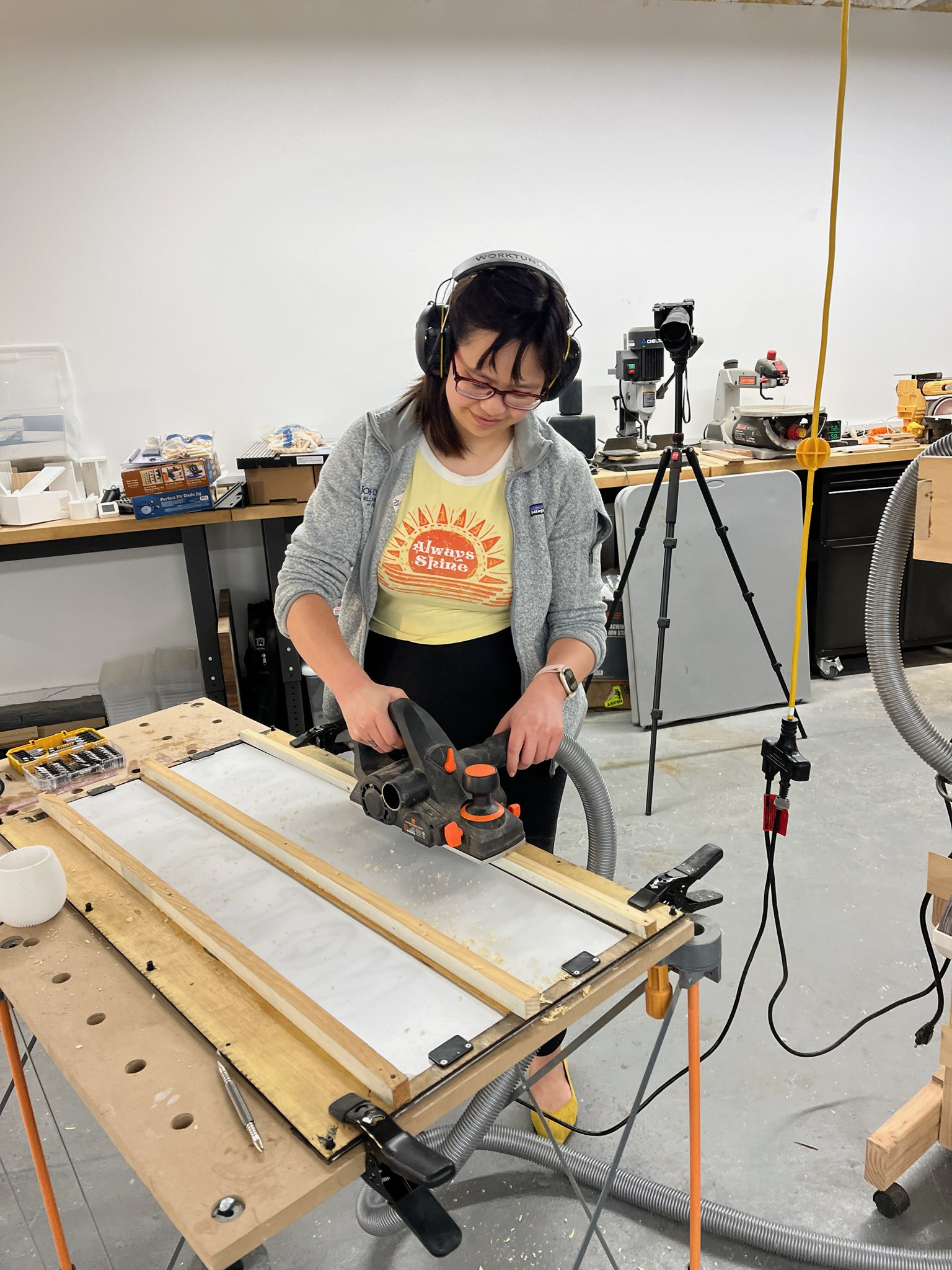
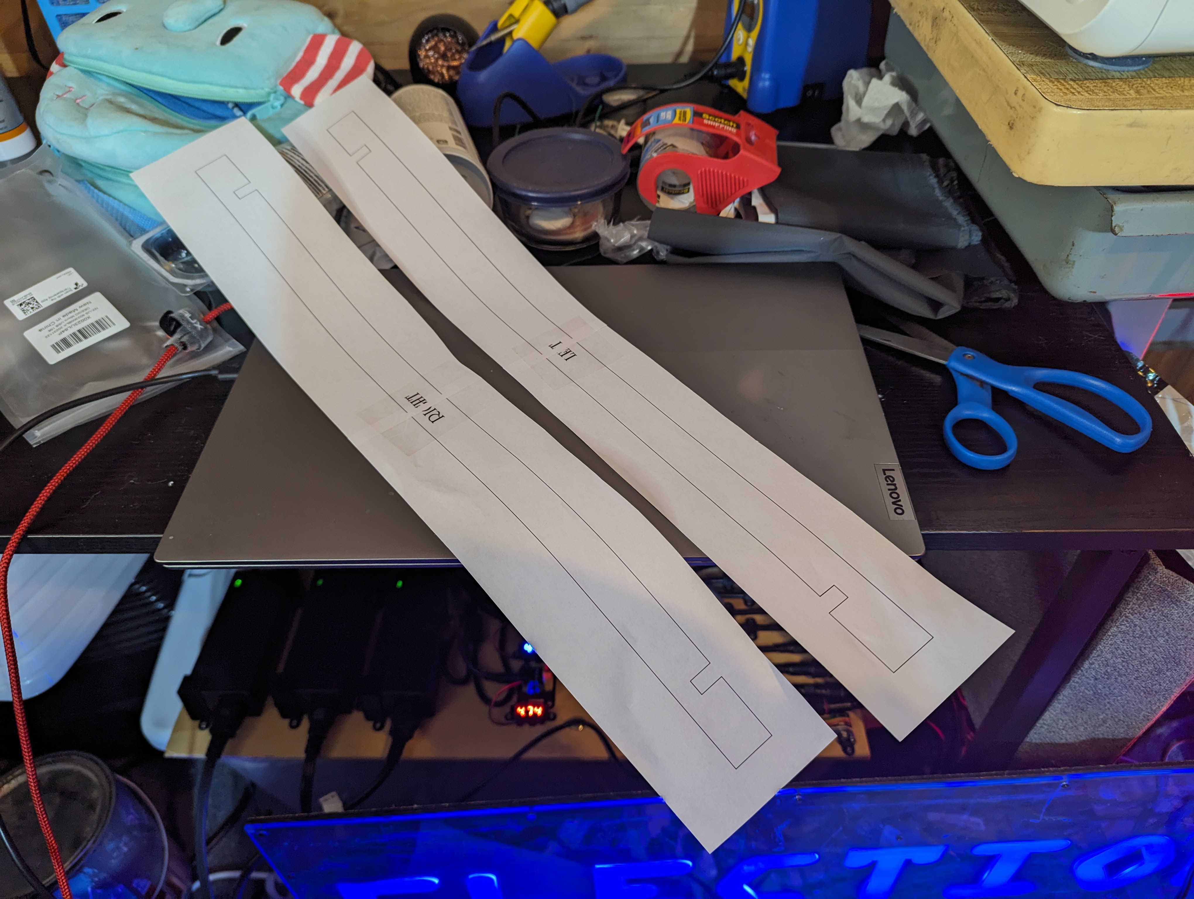
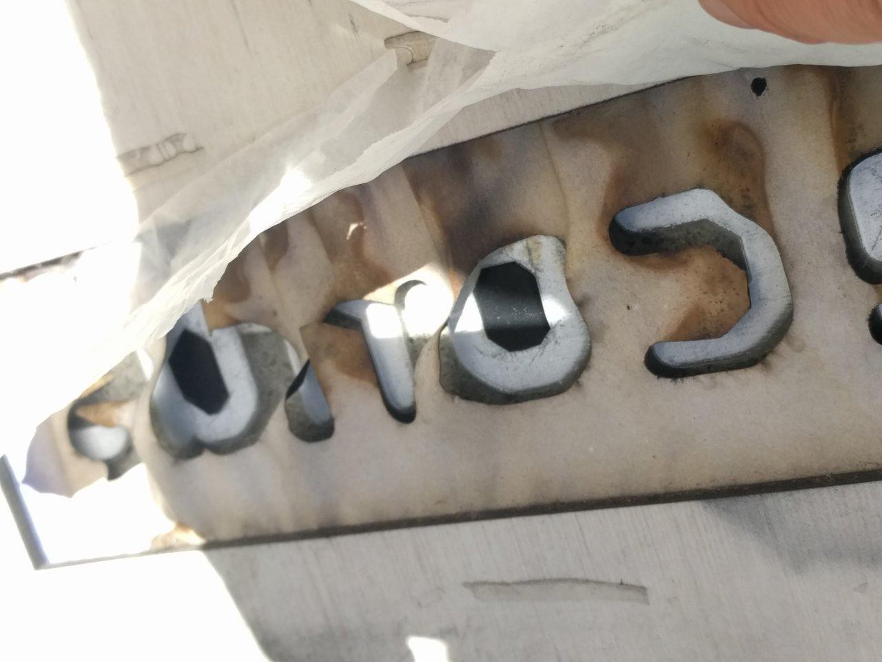
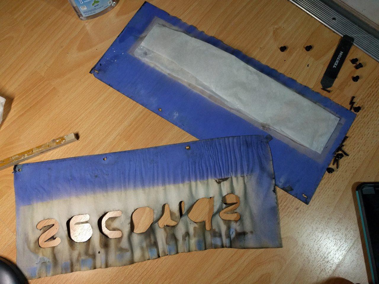
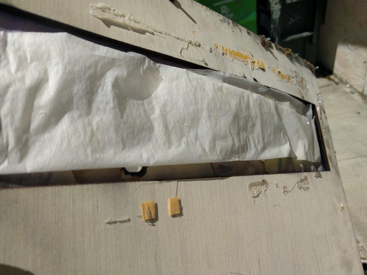
 I did up one panel first and tested to make sure it fit, before following the same procedure with the rest of the panels
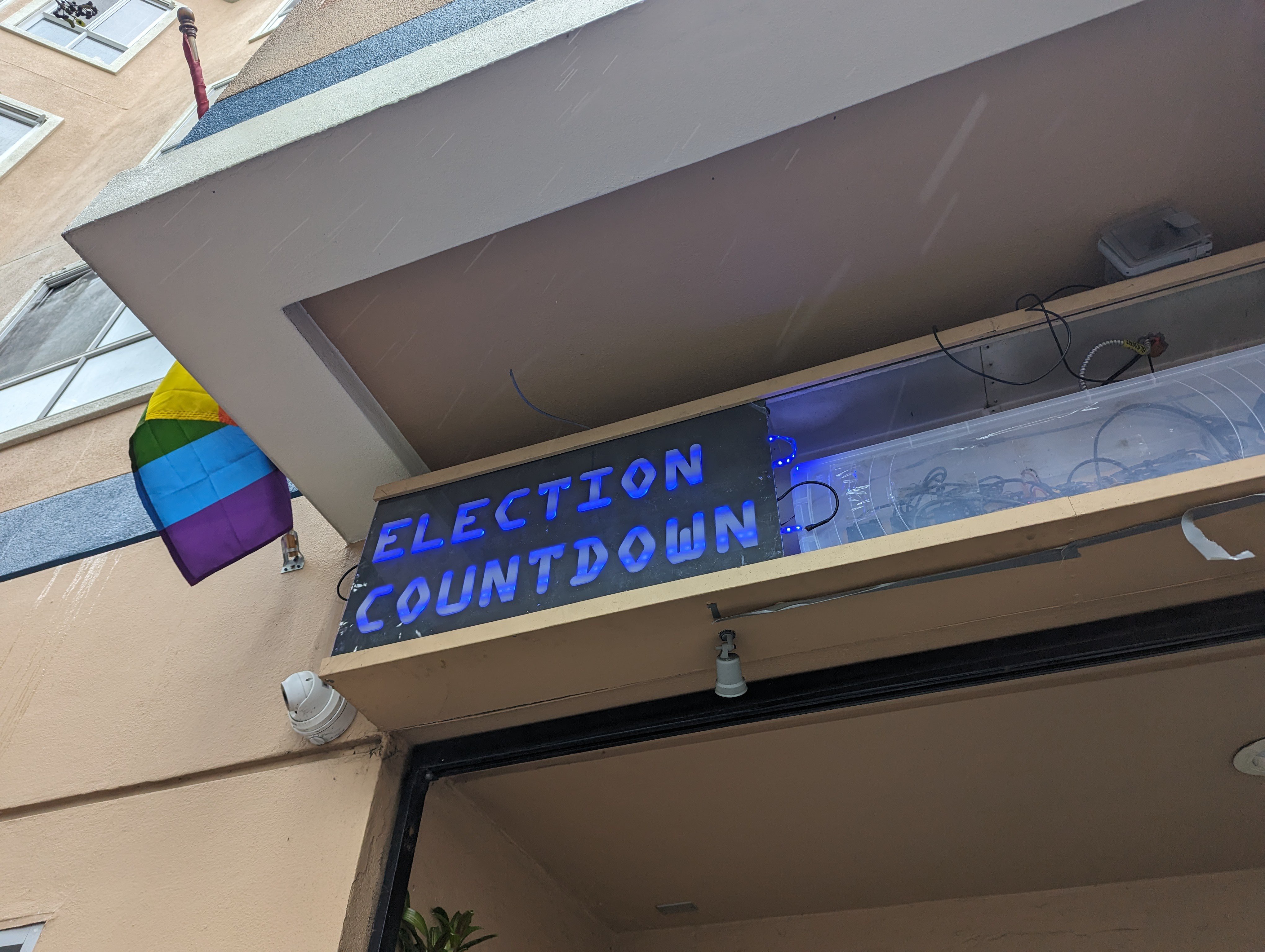


 terrag
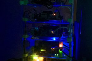
 Colin Alston
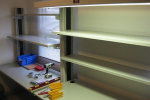
 Quinn
Quinn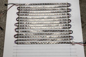
all will become clear in time. I just got the panels in hand and will show it all when I do more write ups. Doing a lot of cleanup at the moment! :P
there are 9 panels - some have 2 digits, some have words. its all LED strips. Keep following, Ill post more soon :)