Close
0%
0%

Election Countown Display

A giant 9 panel display using WS2812 chip LEDs

Similar projects worth following
A friend asked me to repair this very hacky hack hack giant display - so here I go! It needs a lot of work but it's a cool project worth documenting.
I inherited it, along with documentation from a local hackerspace. Let's see if I can give it some professional TLC and make a durable and lasting device :)

This display is powered by a wifi-controlled ESP32 WEMOS module.  The specific breakout kit I inherited was a NodeMCU 32-bit module.

There are 9x panels in total (or so I'm told, I only 1x on hand) with 9 seperate control signals.

The panels all use the popular WS2812 "intelligent" LED (chip-based) strips.

These LED's have their own timing specific 1-wire interface, that is sadly not UART.

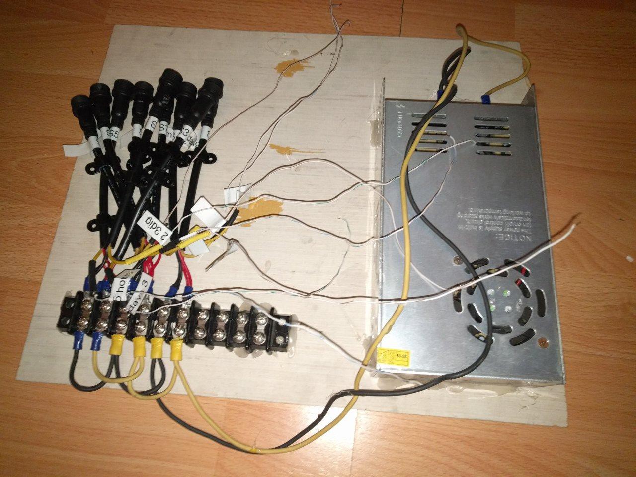
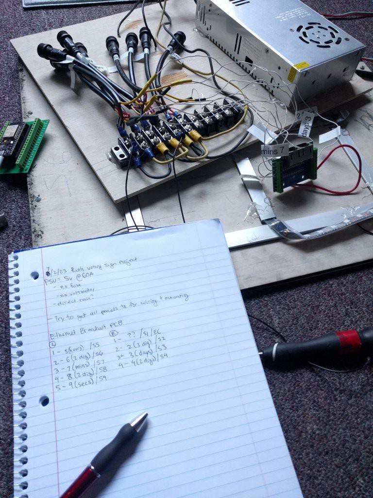
The power board looks like MDF plywood with lots of hot glue, a power supply, breakout screw terminals, and some (nice) weatherproof terminal sockets.  Unfortunately, this is just about the only thing properly weatherproof-ed.
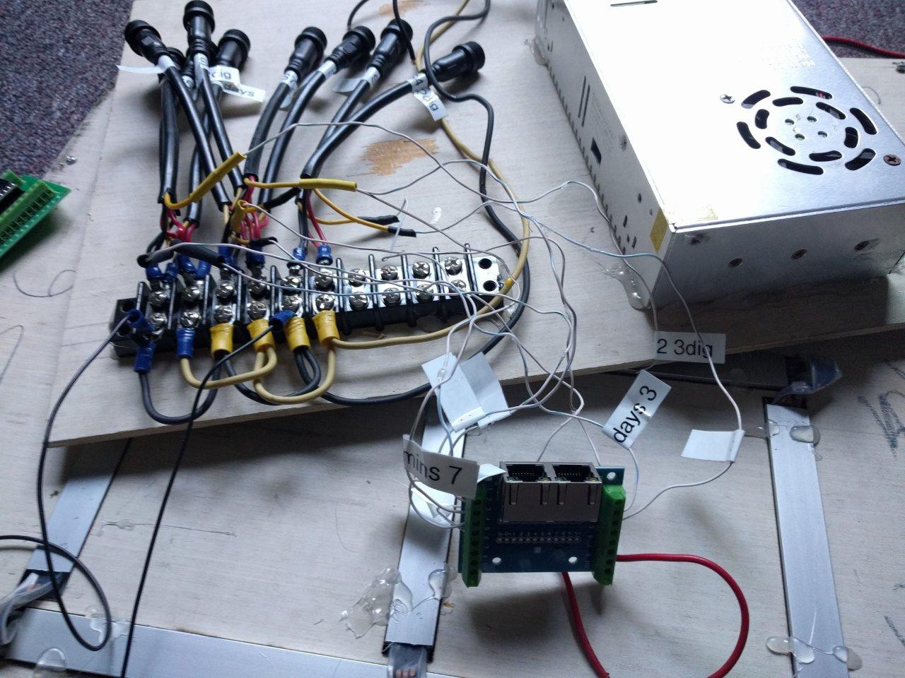
* The power supply is rated 5V @60A.  It has no external fuse, and an open frame design, not suitable for weatherproof.  There is a soldered glass fuse inside, but that doesn't offer much comfort.  There is also one of those super cheap pots for adjusting output voltage.  It needs to be replaced with an enclosed and safe PSU.  Bonus points for having an on/off switch, pluggable AC, and a replaceable fuse.


*Due to wifi proximity issues, the MCU output to the LEDs is distrubted through an ethernet cable, that way the ESP32 can live inside somewhere near the router and run the ethernet to the outdoor panels.  I'm not a huge fan of this, especially if the cable is going to be many feet long, due to the 1-wire fast pulses of the LED chip controllers.  Strongly considering adding a clock buffer to sharpen the rise/fall edges for accurate reads.

*The system needs a 3.3v --> 5v level shifter. 

Nothing too complicated there, although doing this within spec does offer some considerations.  For exmaple, a 74HC245 is an obvious choice.  But the datasheet shows a logic high detection of 3.15V when VCC = 4.5V.  

Since we're trying to power this off a 5V system, this could pose a real problem sending 3.3V signals that it might not actually register.  An easy solution to this could be a series diode on the VCC line to regular the level shifter closer to that 4.5V range.


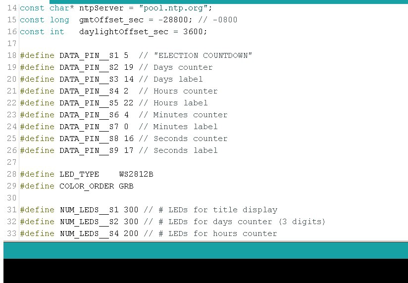
*There are coding issues.  I don't currently have the latest working firmware, and what exists here utilized a lot of delay() functions instead of millis().  Most importantly though, the configuration of GPIO pins does not seem to consider startup condition issues that ESP32's have.  I likely need to change them, assuming there is no special pin functions being used.

[to be continued...]

  • We're in the news!

    Ruth Grace Wong03/13/2024 at 04:40 0 comments

    While I was weatherproofing the sign, to my surprise, a KRON4 reporter came and interviewed me! https://archive.org/details/KRON_20240306_010000_KRON_4_News_at_5pm/start/1080/end/1380

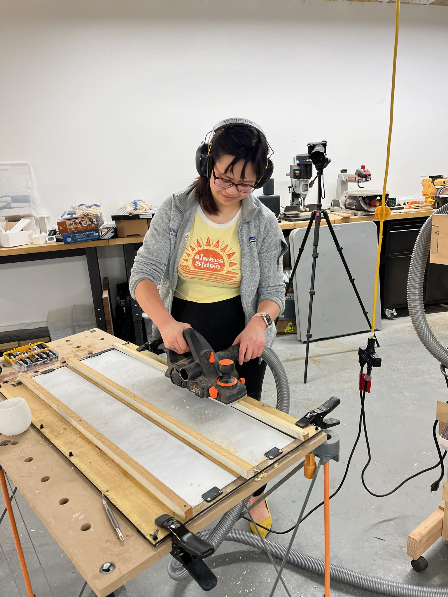
    So excited to have this project done, and very grateful for the help of all my friends - Cripalishus for holding the project down while I had a baby in July, Dave for teaching me how to use his electric hand planer, and Dan and many other friends who gave me advice along the way.

    Here's a video of the big reveal

    With that, here are some project links:

    GitHub: https://github.com/ruthgrace/mannys_sign

    [other links like 3d prints and stuff will be added soon...]

  • ironing out the kinks

    Ruth Grace Wong03/13/2024 at 04:39 0 comments

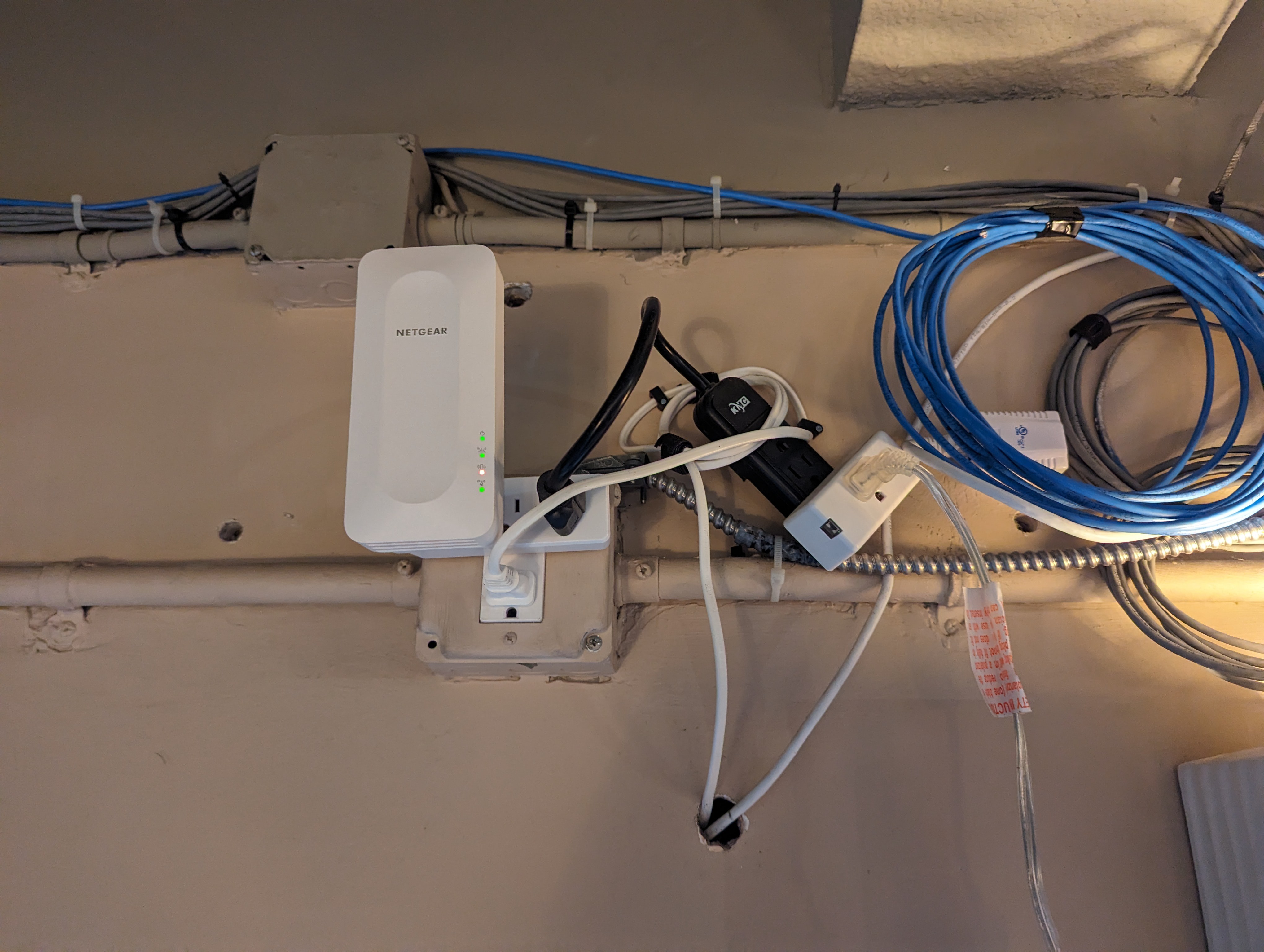
    Using the programming cable, I realized that the power board was not able to connect to Wifi when it was up in the bracket. I bought a Wifi repeater and installed it on the wall inside the restaurant closest to the sign

    Finally it was time to start installing the panels!
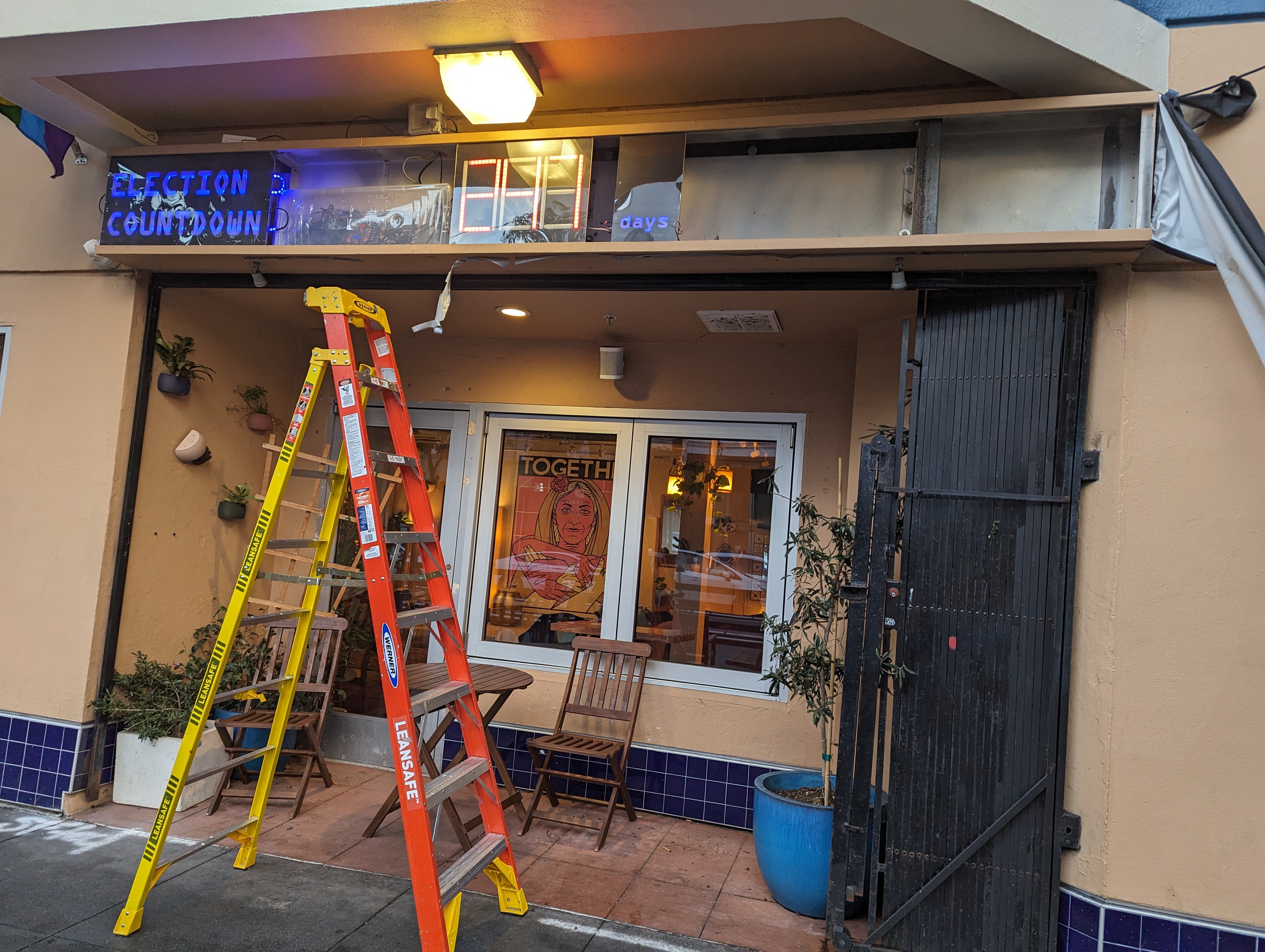
    When I got to the end, I needed to plug the last two panels inside the plastic housing before putting them in the bracket, but the wire wasn't long enough to have them on the floor. So I duct taped them to the wall. Manny took a video:

    At this point it was a day before the big reveal was scheduled! Here's a video I have of it working just before I covered it up again with the blackout fabric.

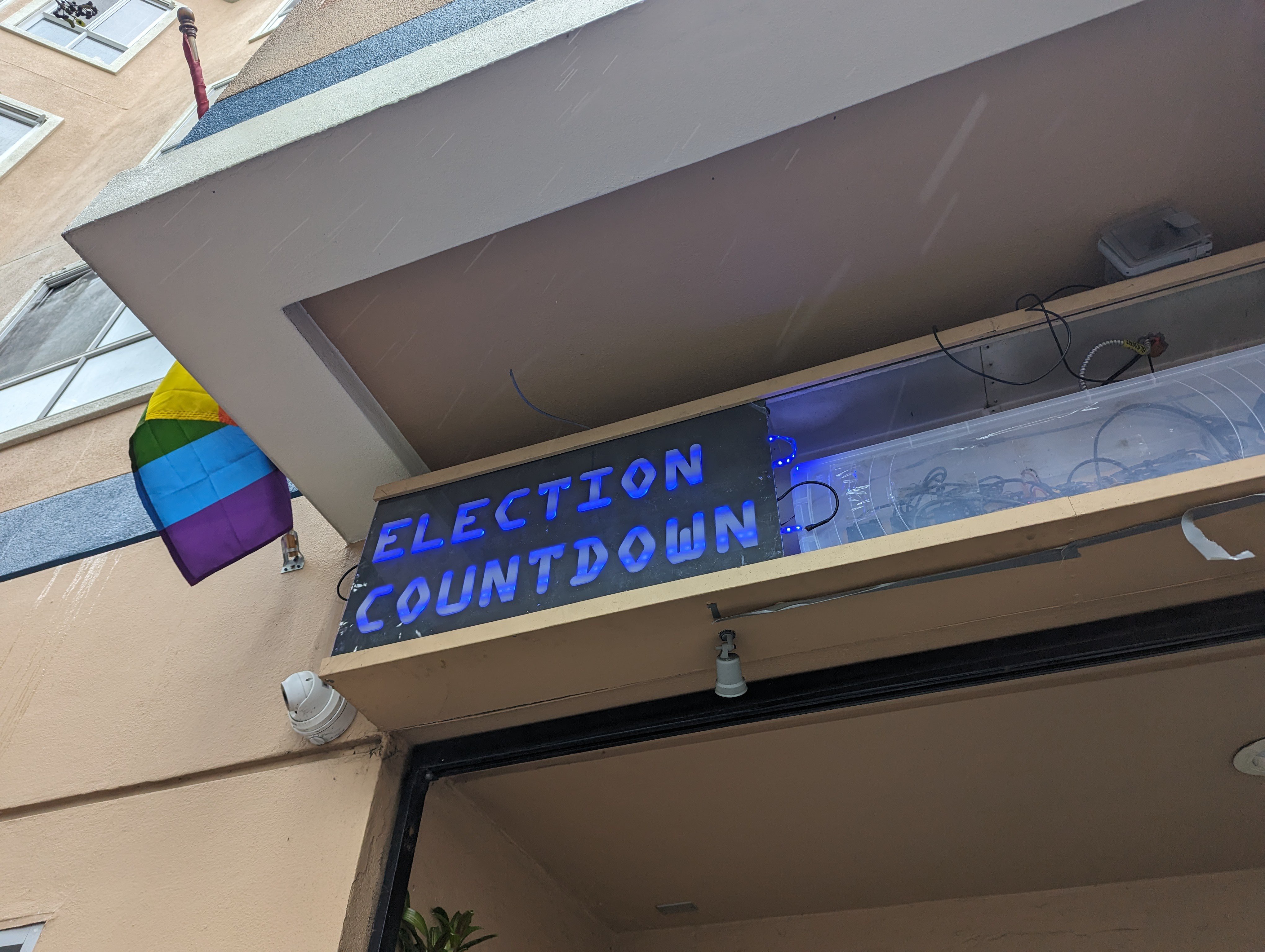
    The reveal of the sign was scheduled for March 5th, the last election before the presidential election. I weather proofed the sign by putting in my acrylic cover pieces (big panels for the front, custom laser cut pieces for the ends of the bracket), and put clear silicone caulking along all the edges.

  • installation attempt...

    Ruth Grace Wong03/13/2024 at 04:39 0 comments

    The programming cable

    Following installation prep, the first thing I wanted to do was make sure that I could access the programming cable even after the sign was installed, so I could update the code without having to take everything apart. This was a struggle:

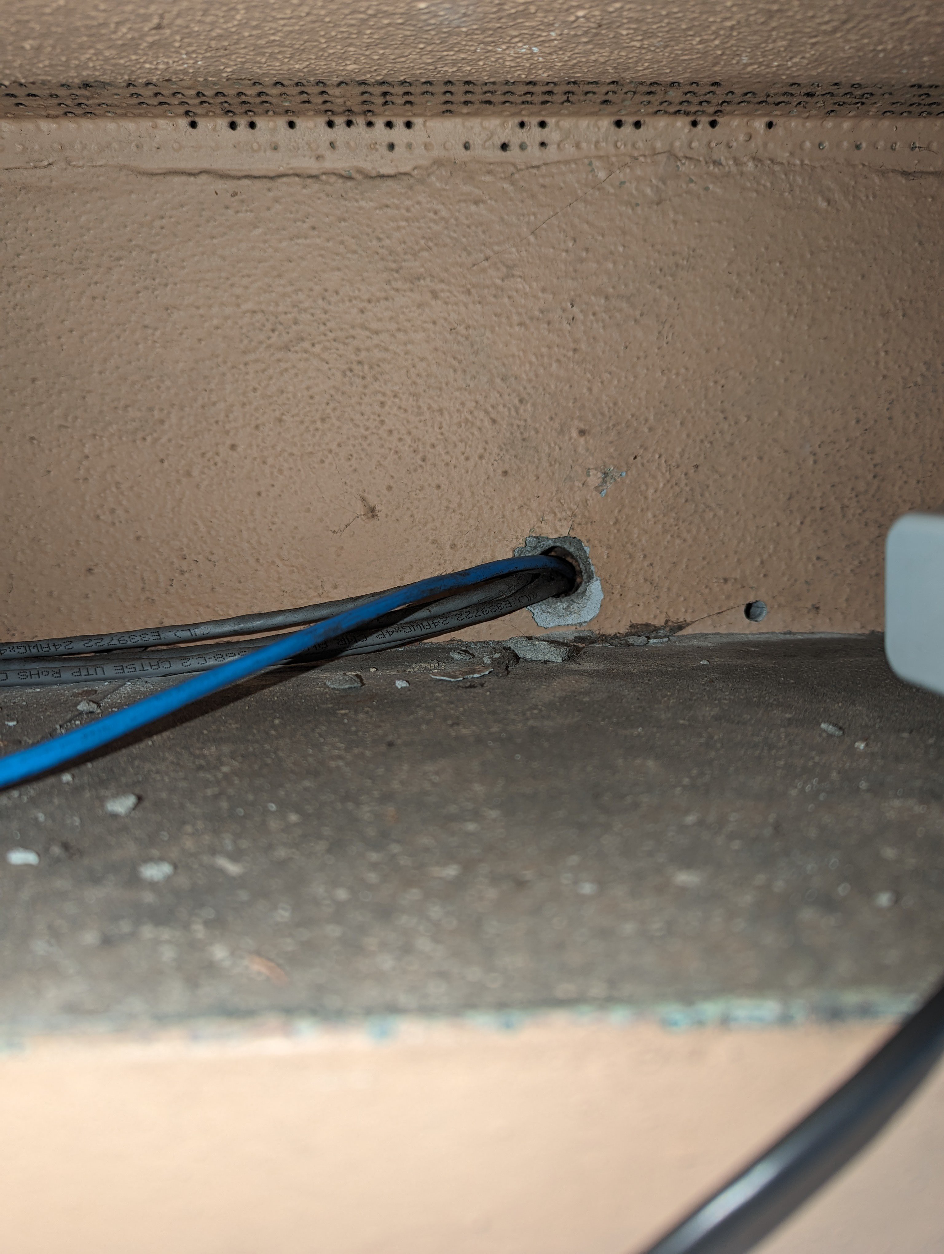
    First,  I tried to thread it through the wall. At the time, I had a USB micro to USB A cable, and the USB A cable was not big enough to fit through the hole in the wall.

    So i got a USB micro to USB C cable, which i was able to get into this side of the wall

    only to find that I couldn't get it through the other side of the wall. I made the hole in the wall a little bigger (fortunately this was easy since it was just drywall) only to find that INSIDE the wall there was a piece of wood with a small hole that all the wires came through, and I could not reach inside to make THAT hole bigger. (the hole with the wires coming out is above the light)

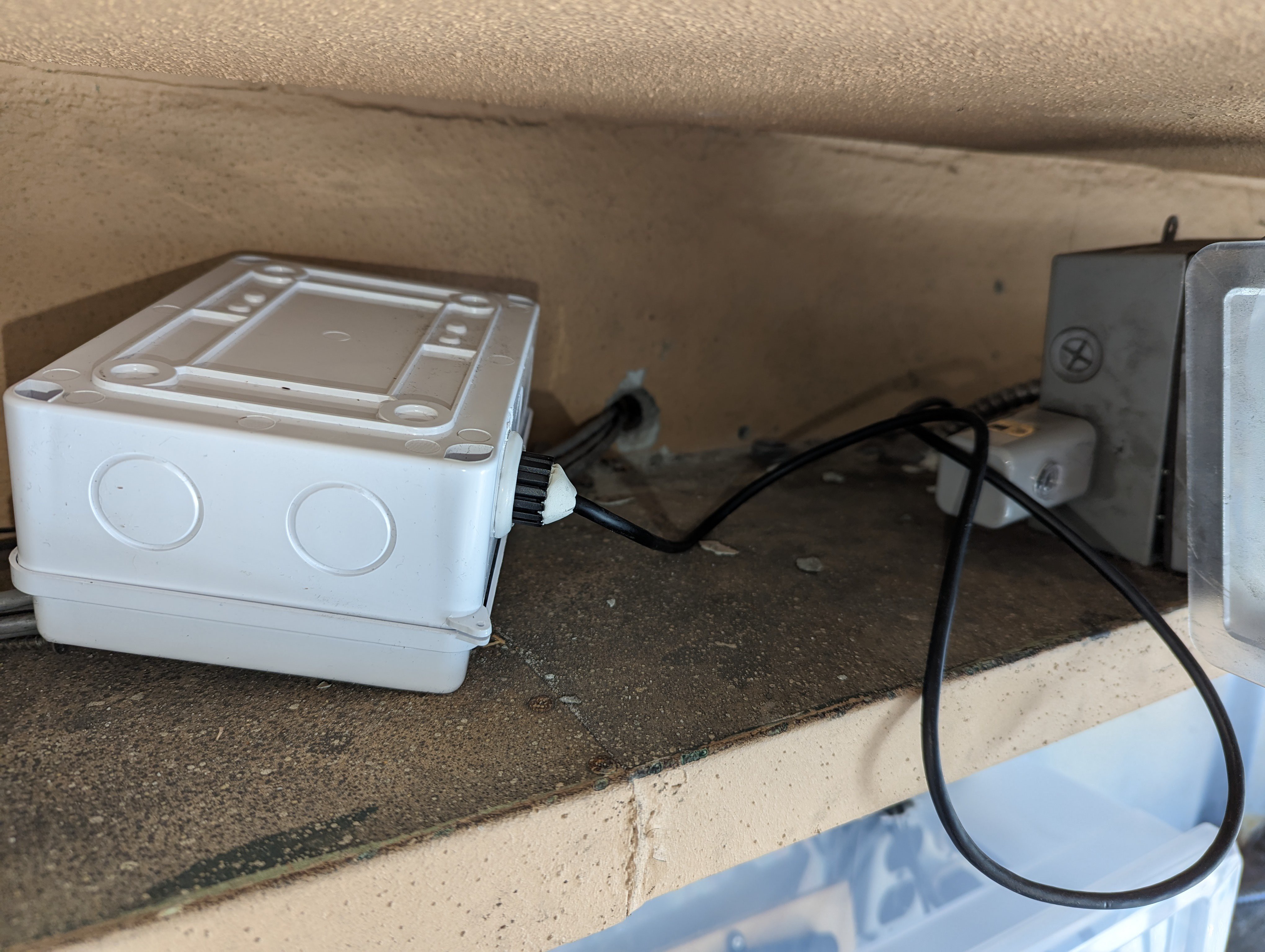
    So I gave up and used a waterproof housing to put the cable in that sits on top of the bracket for the sign. I used Sugru to seal the part where the wire comes out of the bracket, and where the wire comes out of the waterproof housing.

    Worst fears confirmed - the panel doesn't fit D:

    We had made the panel thicker to improve the LED diffusion, thinking that the panels were installed by being horizontally inserted into the bracket and then tilted up until they were vertical.

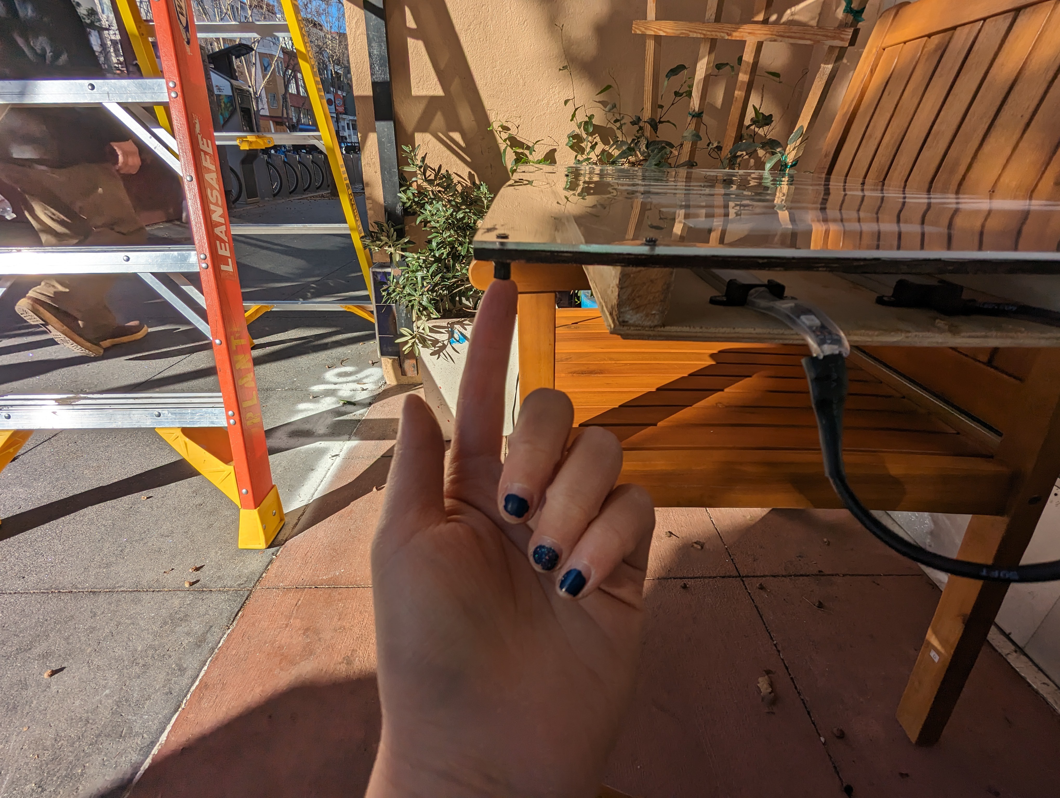
    But the panels were actually installed in these channels on the bracket, and now they were too thick to be inserted in the side opening.

    So for the time being, I installed the power board inside a tupperware, and put outdoor putty under the lid to make sure it stayed closed. Here's a video of it before I taped the bottom of the blackout cover down with duct tape.

    Making the panels thinner

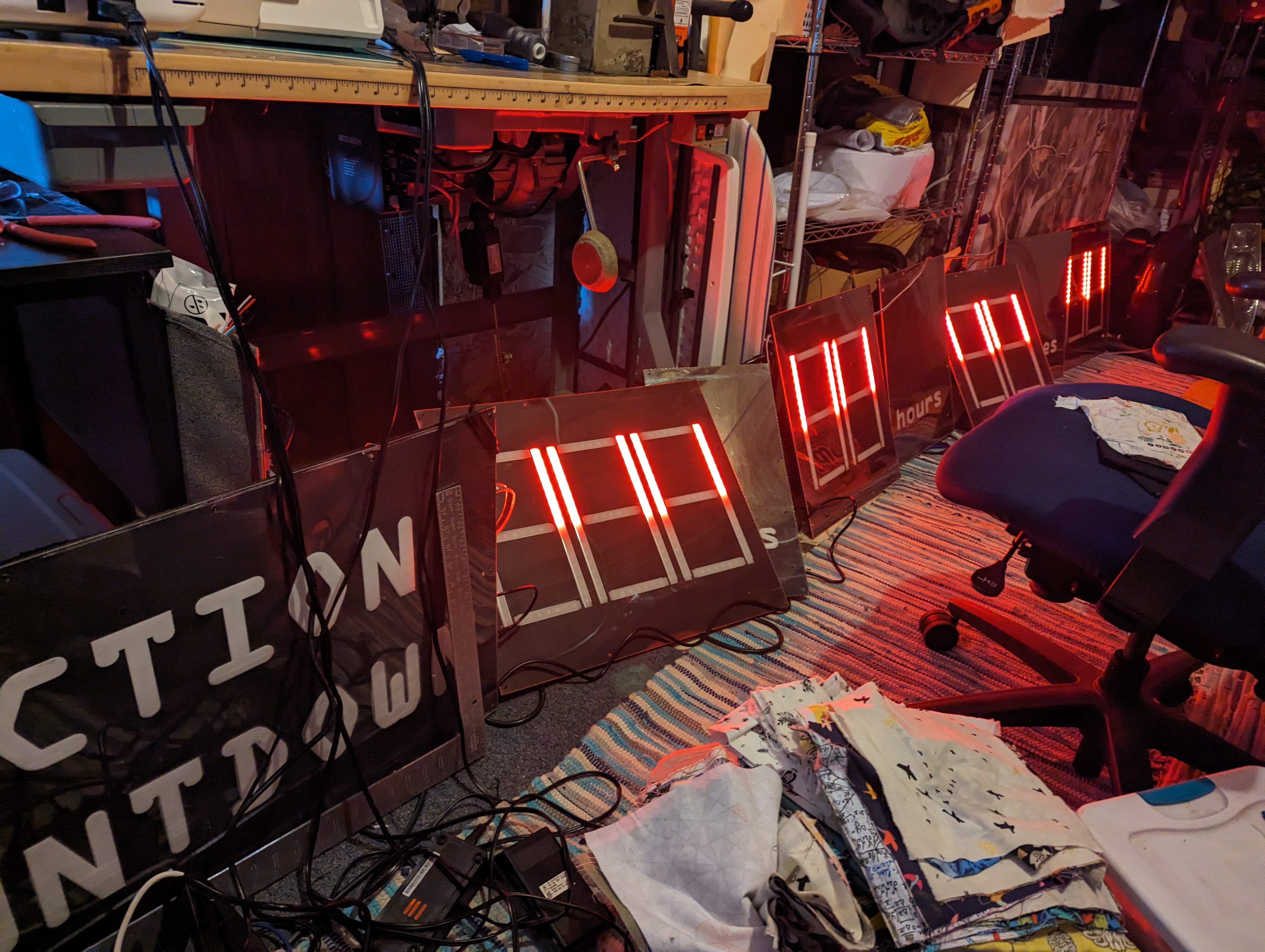
    Luckily I was able to find a friend with his own woodshop including tan ELECTRIC hand planer to shave the wooden spacers on the panels down (thereby making the diffusion of the LEDs terrible, but -- done is better than perfect!)

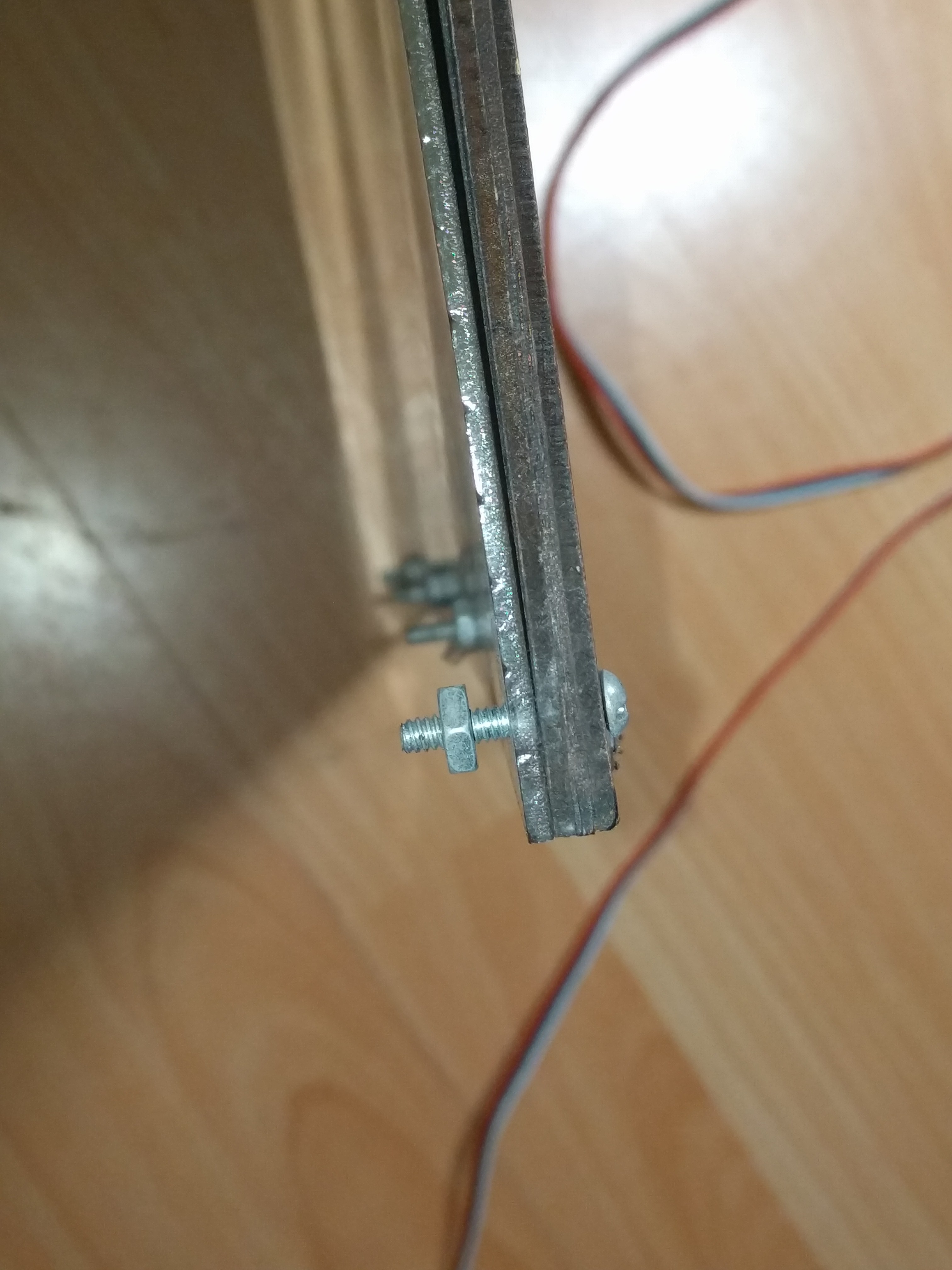
    In addition to that, I had to replace the wood backing with thinner acrylic, and also reverse the direction of the bolts on the panels for them to fit.

    I did up one panel first and tested to make sure it fit, before following the same procedure with the rest of the panels
  • installation prep

    Ruth Grace Wong03/13/2024 at 04:27 0 comments

    this post is guest written by Ruth! https://hackaday.io/ruthgrace

    segment boundary adjustment

    Several strips of LEDs had to be replaced. After replacement, I adjusted the boundaries of the digit segments. The digits panels each have one looong string of LEDs, and the code marks where each segment of the 7-segment display starts and ends on the LED strip. I did this with some test code that flashed groups of segments for one second each so that I could see the boundaries and adjust them: top vertical segments, bottom vertical segments, and horizontal segments.

    code: https://github.com/ruthgrace/mannys_sign/blob/master/test%20code/Segment_test_code_V1.0.ino

    photo:

    Looking good!

    animation on zero

    I also noticed that there was a bug when the sign counted to zero -- it would continue counting, attempting to do so from a negative number. I updated the code so that instead of bugging out when the countdown reached zero, the sign would continue to display zeros, and fade their color from red to blue, like the visual representation of a swing vote.

    1.00 remove debris

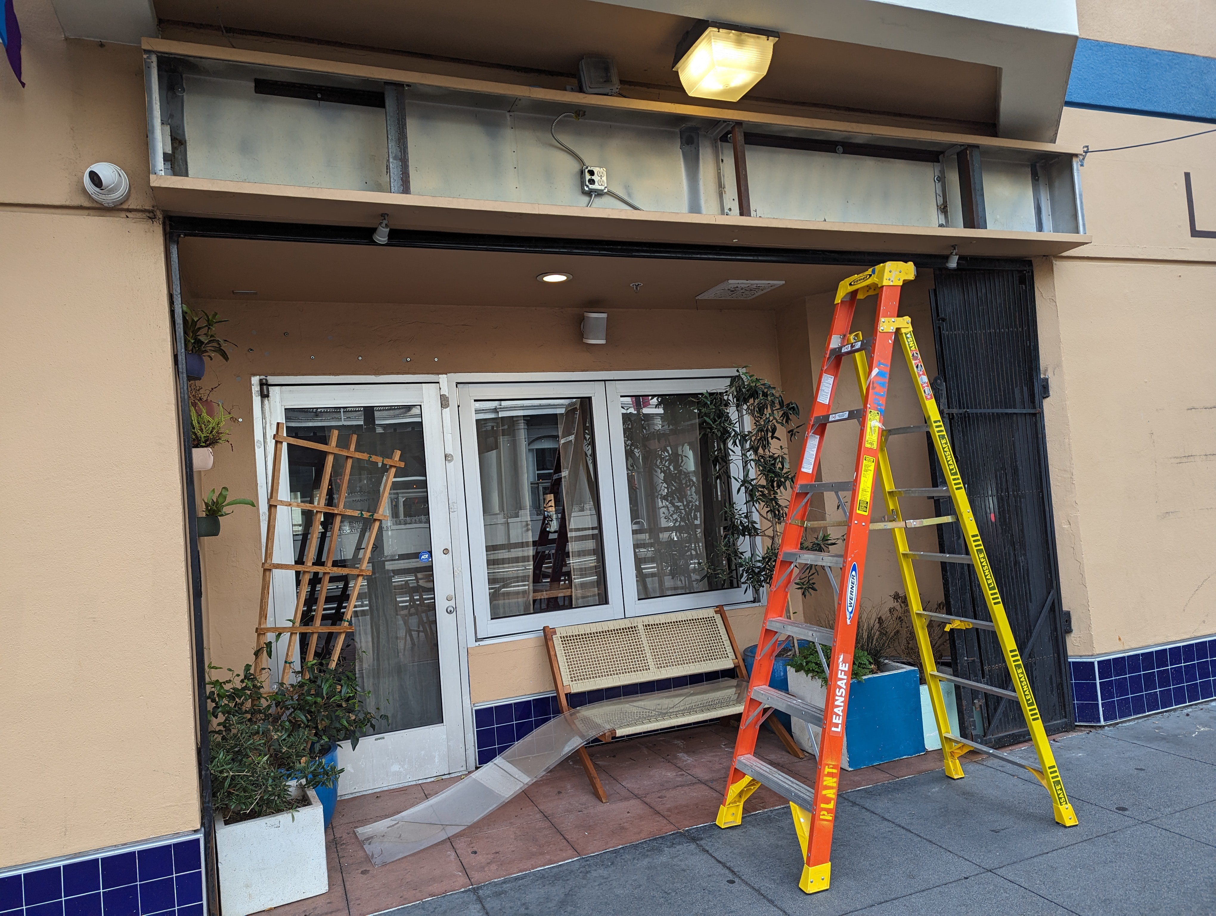
    There were already some plastic sheets in the bracket for the sign, but they weren't tall enough to protect the sign from the weather (they may have been used to hold up the sign from behind, but i don't think that will work now that I have nicer casings for the LEDs). I removed these.

    bracket, ladder, removed plastic sheets on the bench below:

    this is what the bracket looks like after removing the plastic sheets... pretty grimey. maybe I should clean it out next time we're there.

    plastic cover + caulking

    I bought a new taller plastic cover from TAP Plastics and I transported it home on a cargo bike

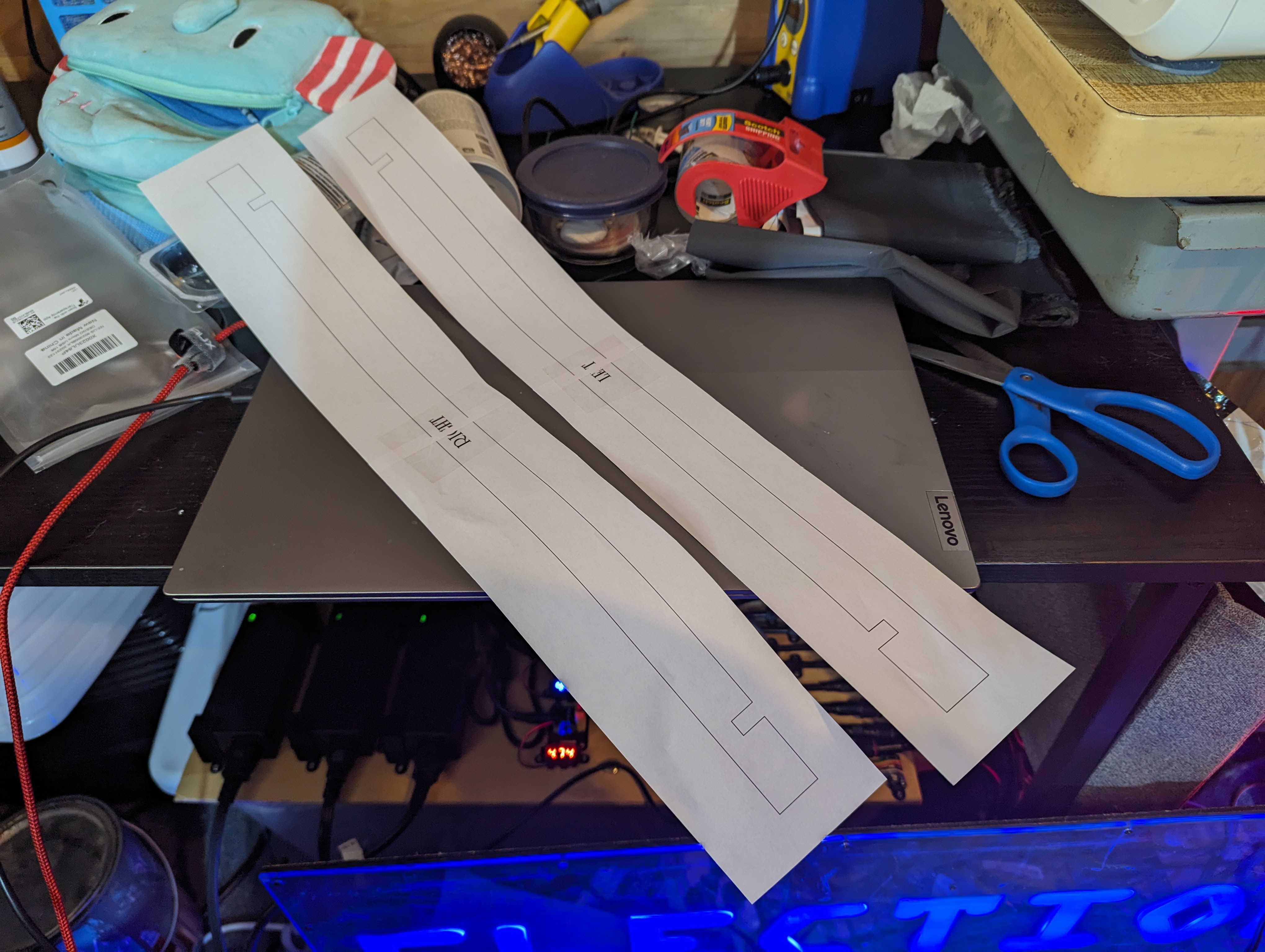
    I also got a small piece of plastic that I want to laser cut a cover for the right and left ends of the bracket out of. First, I prototyped the shape in paper

    so that I could test it on the bracket

    i made some adjustments based on my paper test. The most annoying part of this part of the project was figuring out how to tile a large PDF to be printed on muitiple pieces of letter-sized paper, since I had run out of my Adobe Acrobat subscription. I was able to do it using imagemagick and ghostscript using the answer here: 

    https://unix.stackexchange.com/questions/627887/separate-high-resolution-single-page-pdf-into-multiple-pages

    blackout cloth cover

    The sign should be covered before the big reveal, so I bought some black out cloth and sewed it into one long strip

    I cut some holes where it needs to hang on the bracket and surrounding wall:

    Next I will hem the fabric and secure the holes with Fabritac around the edges so it doesn't fall apart.

  • Power Panel Resurrected!

    CriptasticHacker01/08/2024 at 05:26 0 comments

    a moment of silence for the original microcontroller.  It was missing on arrival, presumably because the original hackers didn't want anyone else wasting time (or getting hurt) trying to fix a sign that was far too broken.  Or maybe it also got wet and fried?  Or its sitting in a roof screwed to a headboard somewhere?

     The original *massive* 50A power supply was overkill, and came in an open-air frame.  A potentially dangerous situation since this already broke once from water damage...


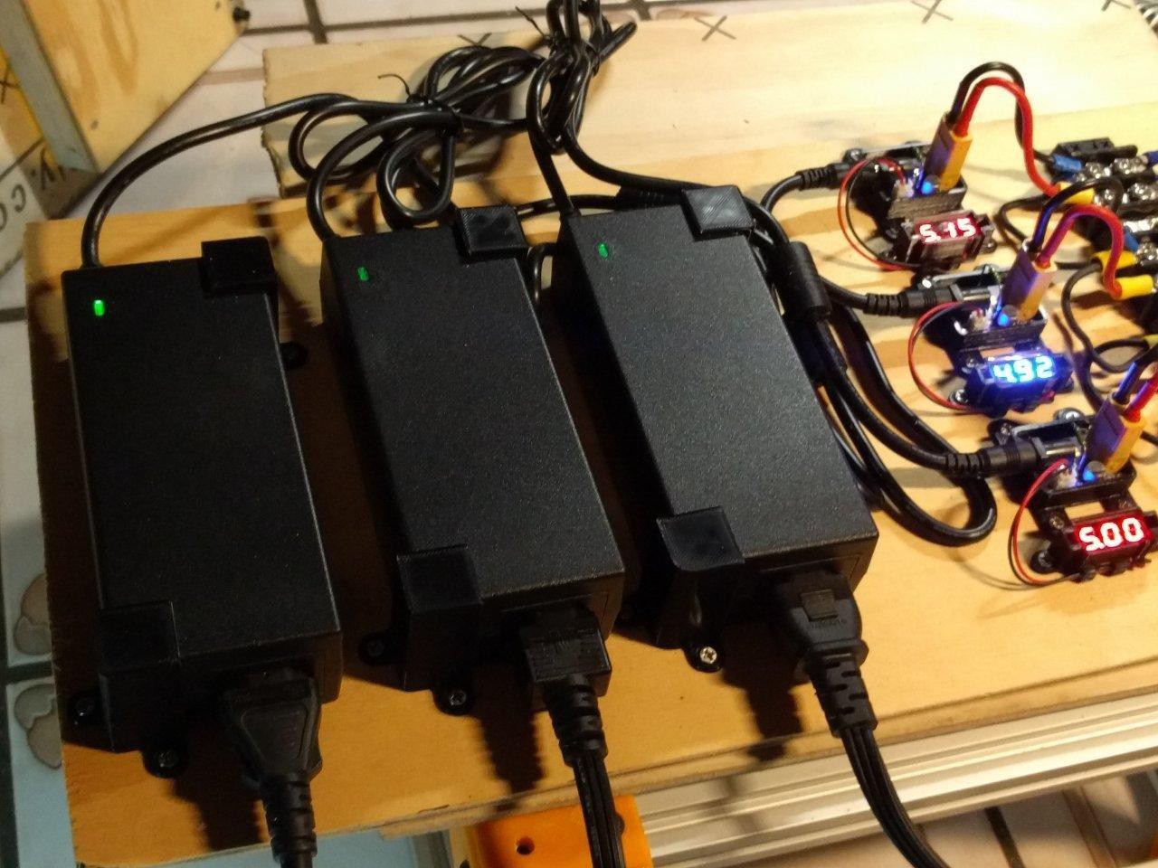
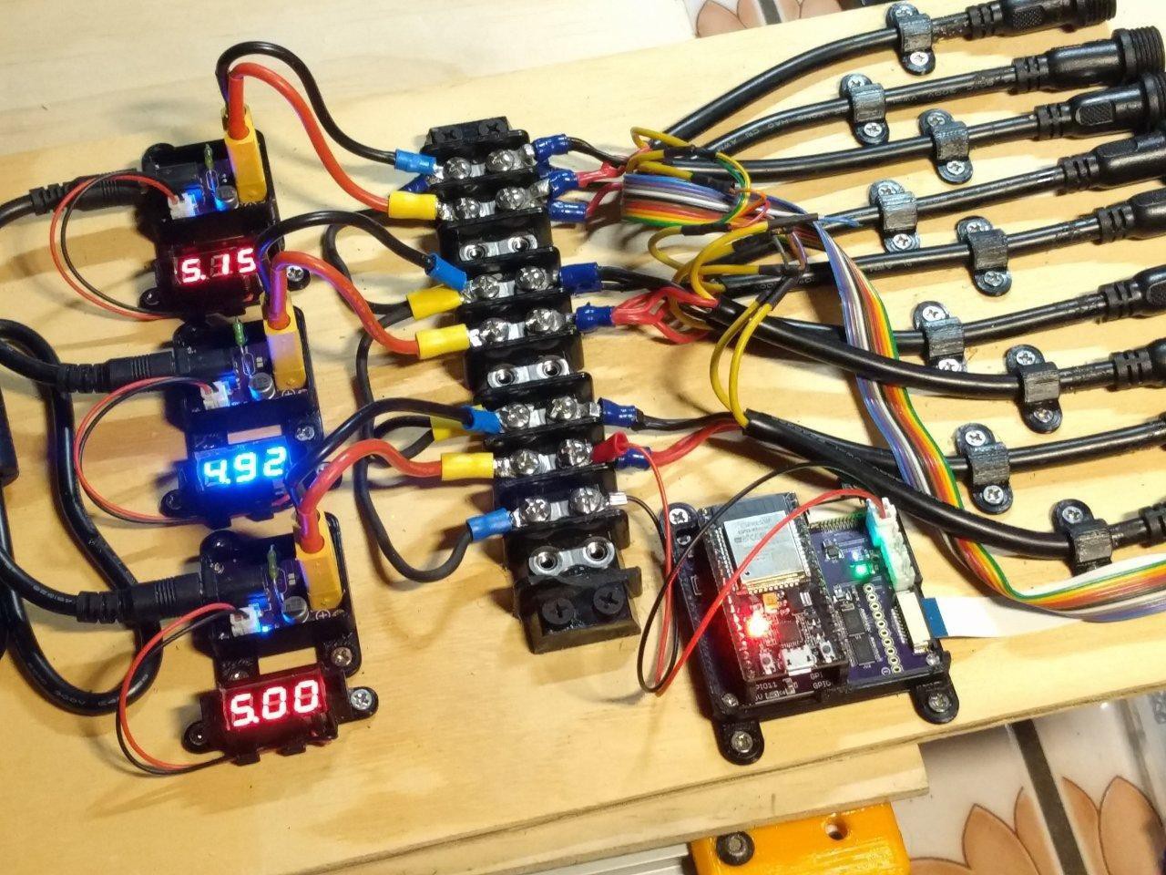
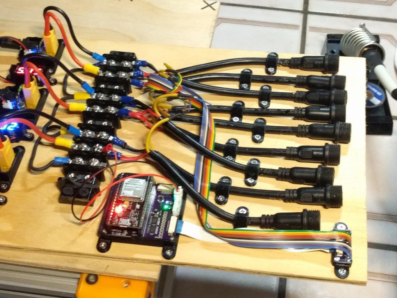
    Below is the power panel after :). These PSU (power supply unit)s are the the beefiest 5V enclosed ones that I could find (15A).

     I designed and 3D printed custom screw supports for them.  I also added voltmeter displays for each PSU (I had some red and some blue so that's why they're different colors), and then I installed my custom PCB with the microcontroller and level shifter IC (74HC245).  It's upgraded with fuse protection, reset button, and other minor tweaks.  I also installed my nice 3D printed strain reliefs.  I went ahead and cut some new plywood to size for the whole

  • Time for a Beauty Touch Up

    CriptasticHacker01/08/2024 at 02:18 0 comments

    --Black out paper around lettering--

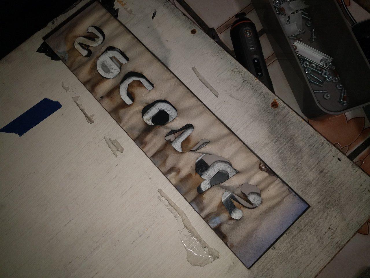
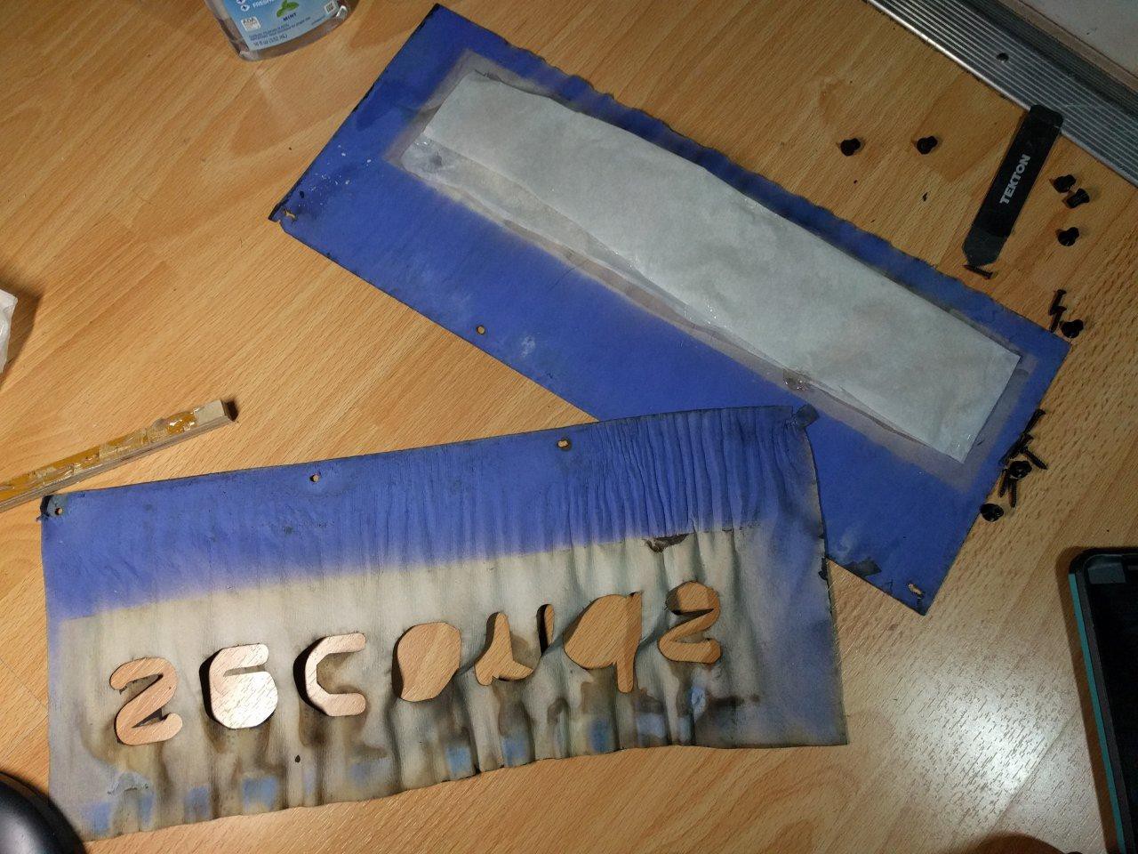
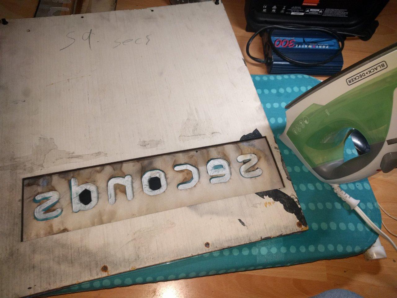
    While waiting for the boards to come in, I did some clean up on the panels themselves. Some of them had significant water damage, particularly the "seconds" panel. 

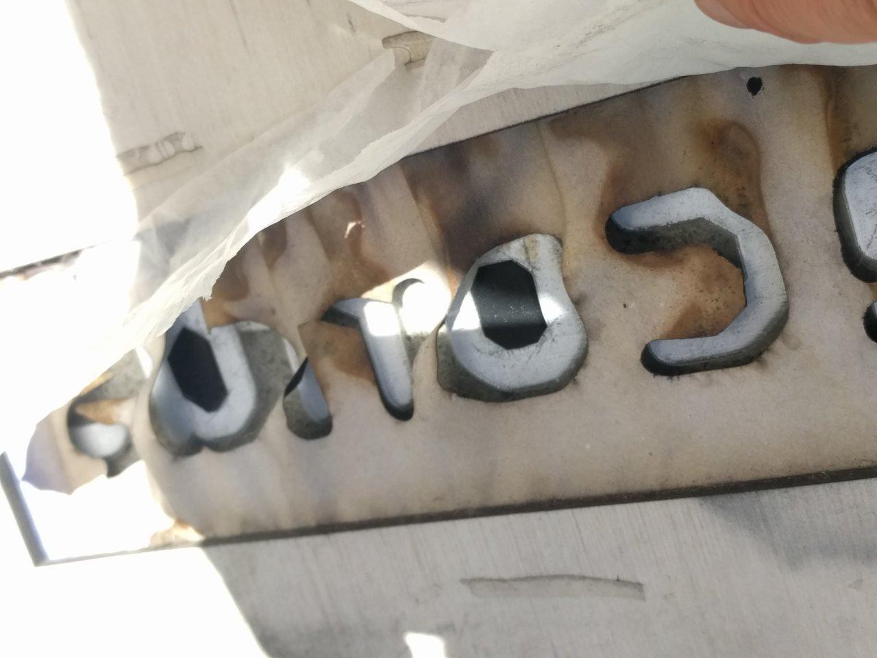
    Normally I would have replaced the lettering entirely, but the person I was working on this for wanted it quick and didn't mind reusing the old water damaged paper. This saved me a trip to the makerspace to use their laser cutter.

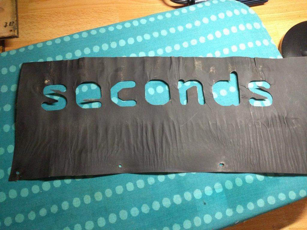
    I steam ironed it flat, by spraying it with water and then using a household clothes iron.   This took a few passes and was a bit of a pain.

    Before:

    After:

    Spray painting the black out paper once again, since the water damage messed up the opacity:

    Touch ups with black acrylic paint on places like the holes in the letters:

    --Upgrading the light diffusion--

    The original diffusion used laser cut paper:

    So much of this stuff was ripped and damaged by rain, it needed to be replaced.  Additionally, I wanted something more weather-proof as well as more consistent illumination results.

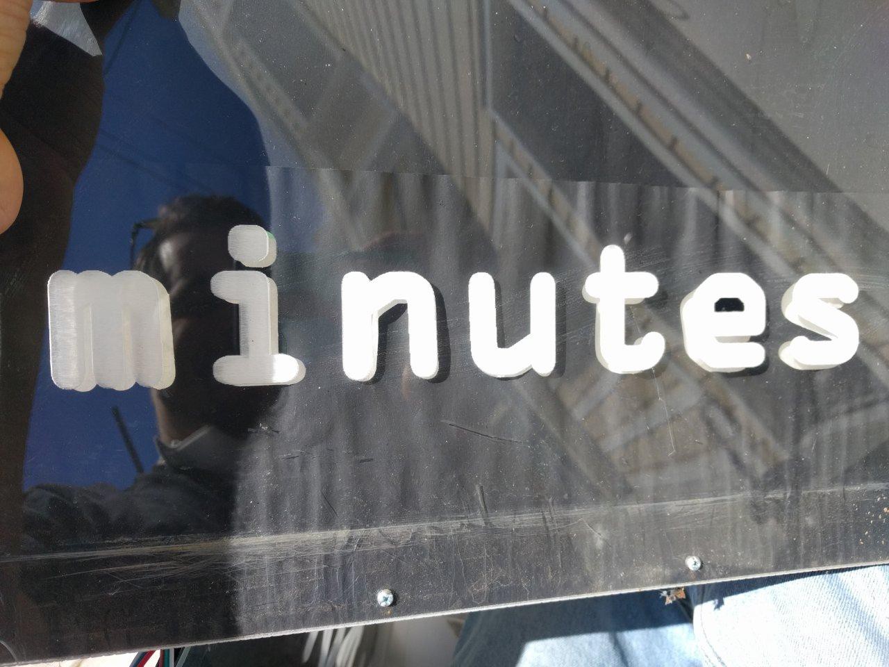
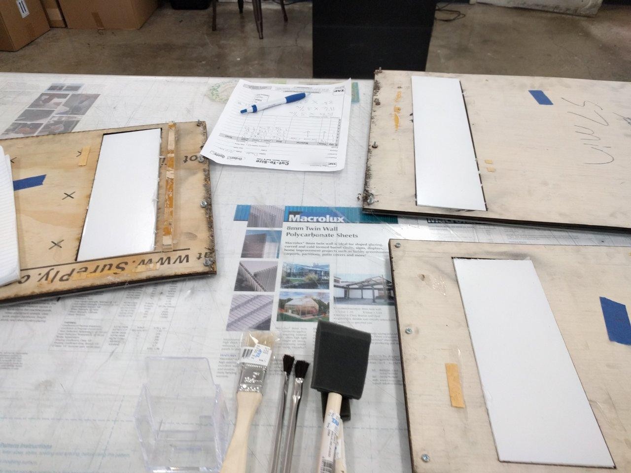
    I decided to replace it all with the most diffused 3mm acrylc material available from TAP Plastics:

    People at the store were super nice and cut the pieces to size at no extra charge :)  They don't have a laser cutter, either!  It's all done by hand with table saws.
    I 3D printed spacer/holders to keep the new acrylic pieces firmly in place

    --Replacing LED Panel Wood Mounts--

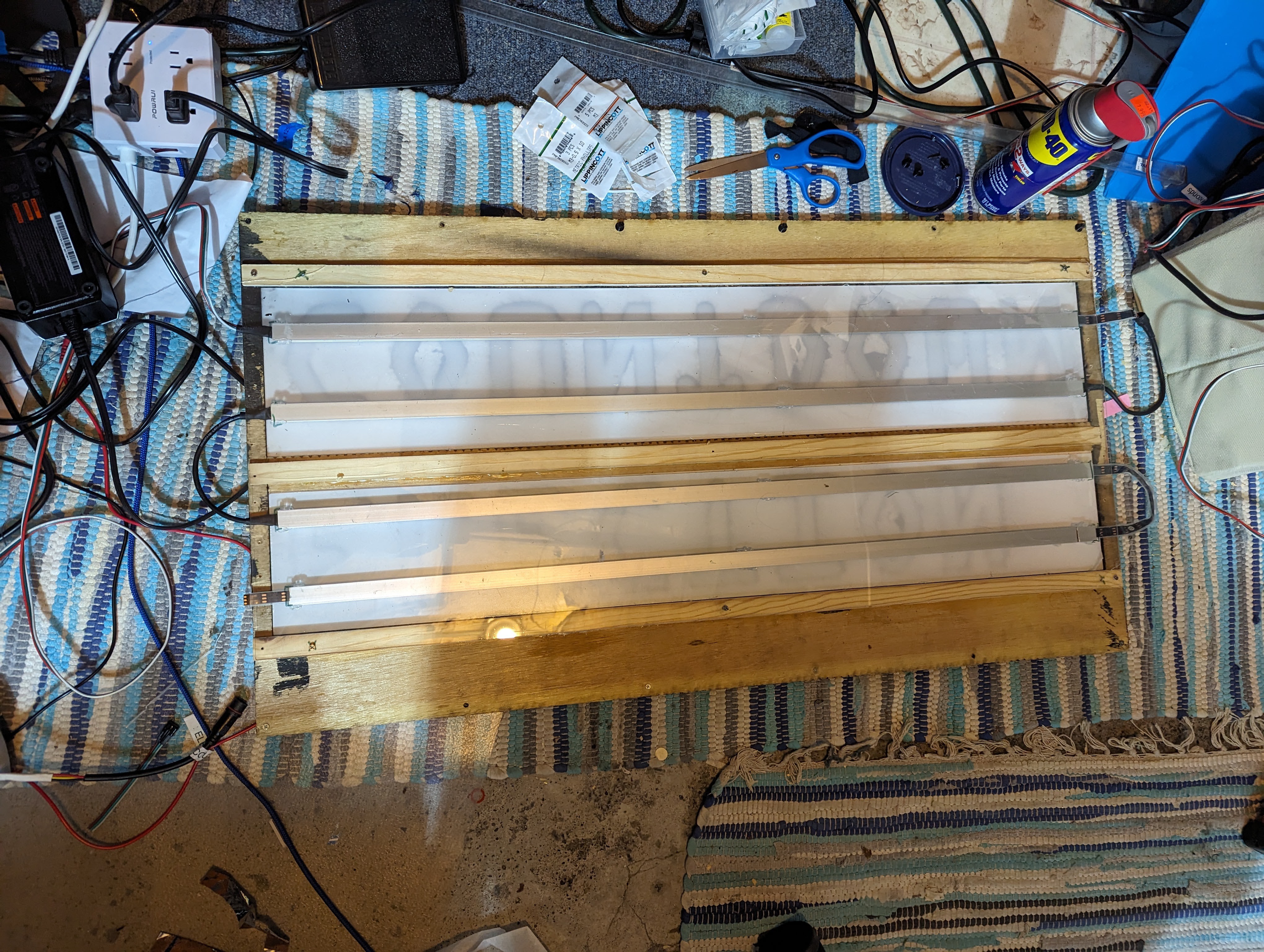
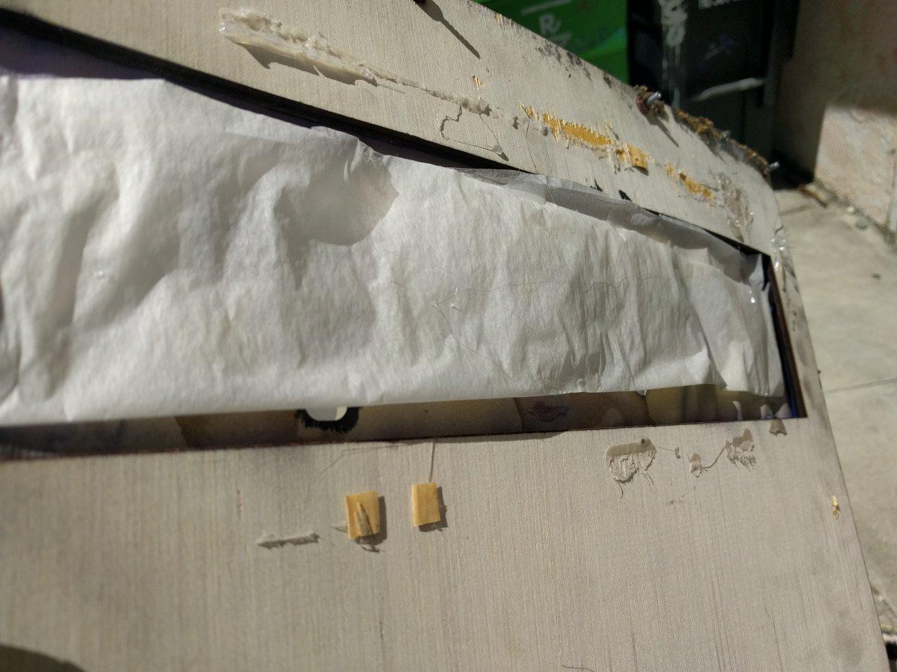
    I also replaced all the wood on the panels since the originals were a total mess on janky hand cut sharp aluminum sheets.  I knew I would need 3D printed parts to properly hold the LEDs in place, and that the aluminum would also be a real pain to drill into.  So good ol lumber to the rescue :)

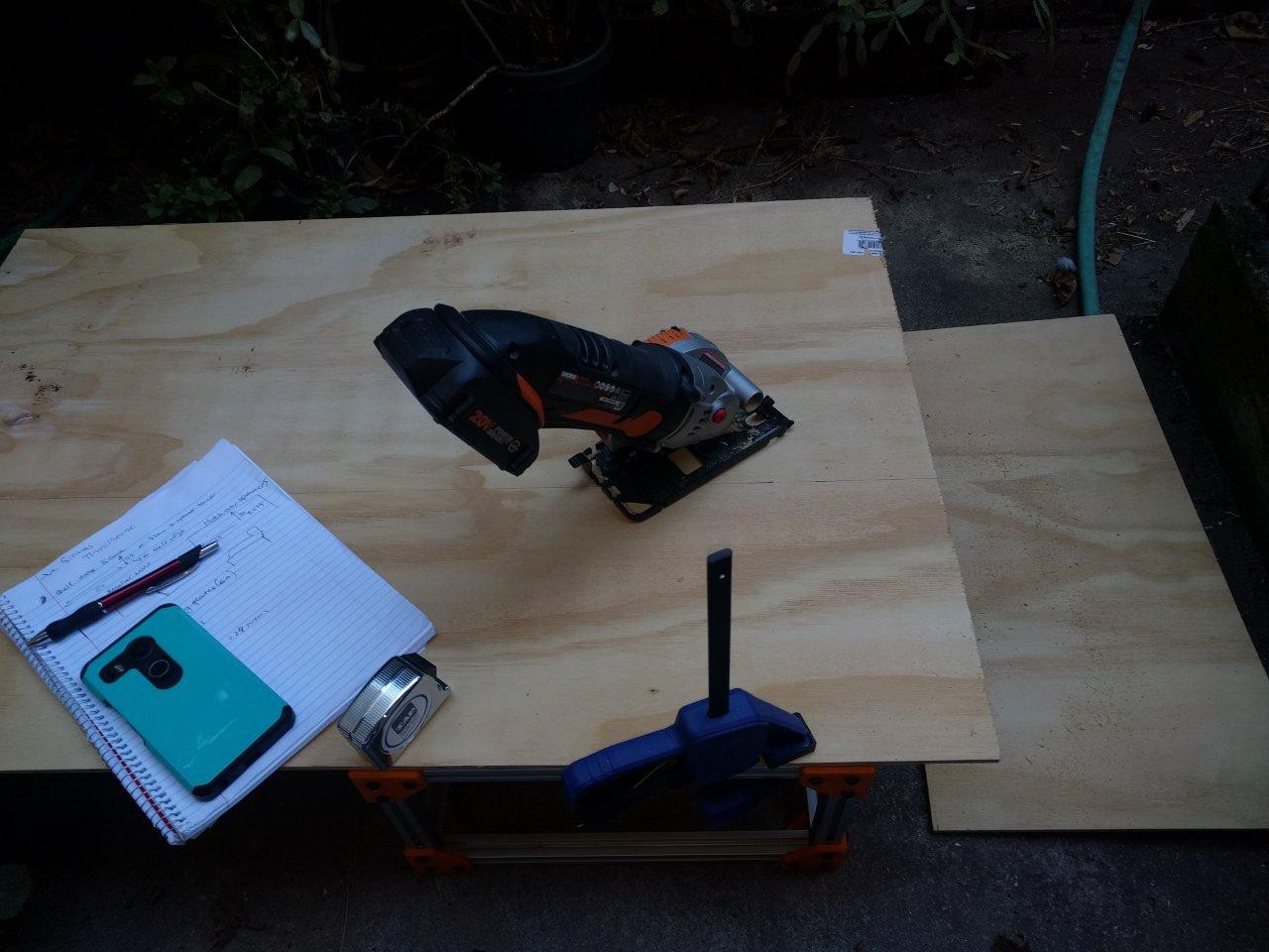
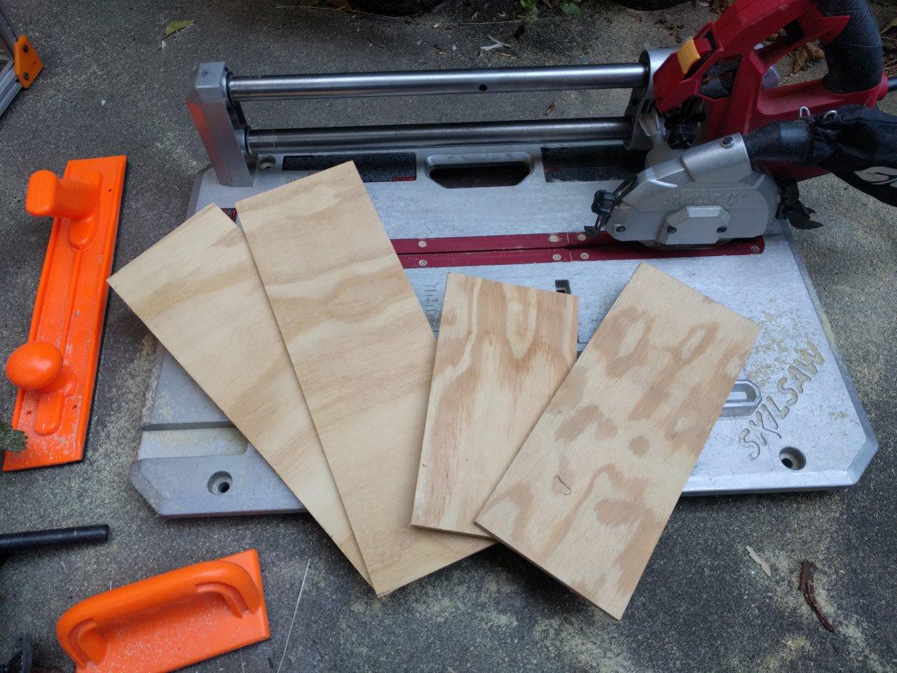
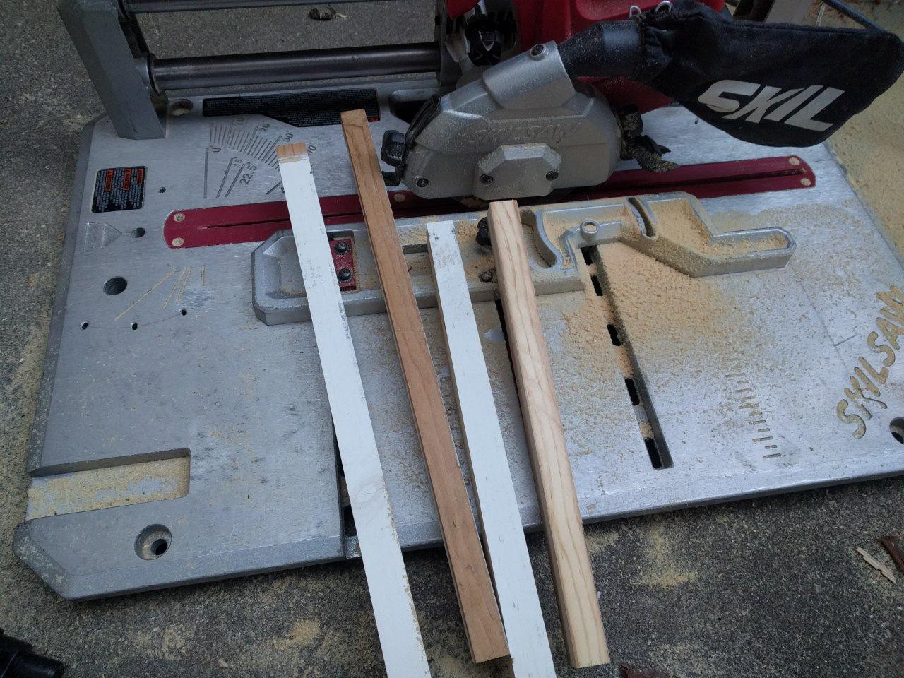
    I hand cut all the wood with this awesome Skil flooring saw I have.  It's terrifically safe since the blade is not exposed like a standard miter or table saw.  However, some of the longer rip cuts needed a portable saw, so I used my Worx one for that, going very s l o w l y (it was also clamped to a metal frame for safety and support).

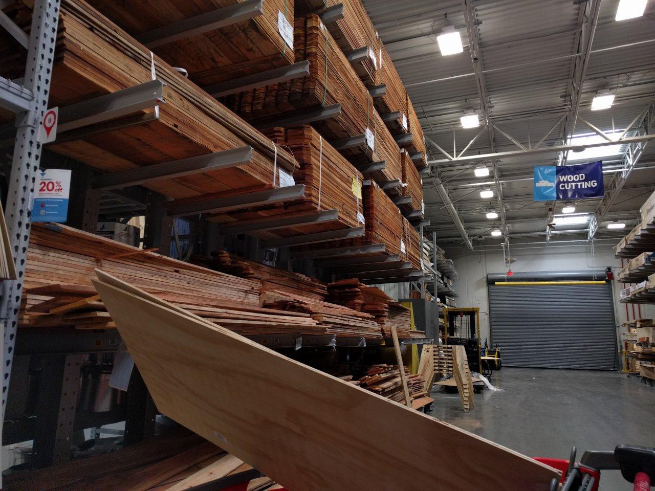
    I opted for this cheapo plywood stuff from Home Despot.  It's meh quality, and in hindsight I should have gotten something a bit better.  I found out that it can warp with moisture, but this might be hard to avoid with any wood, given how thin it is.  The panels have enough reinforcement though that I think it will be OK.
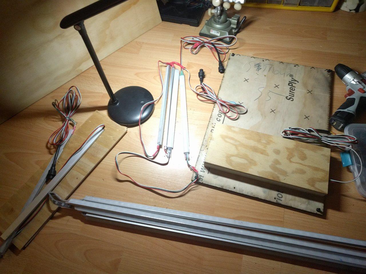
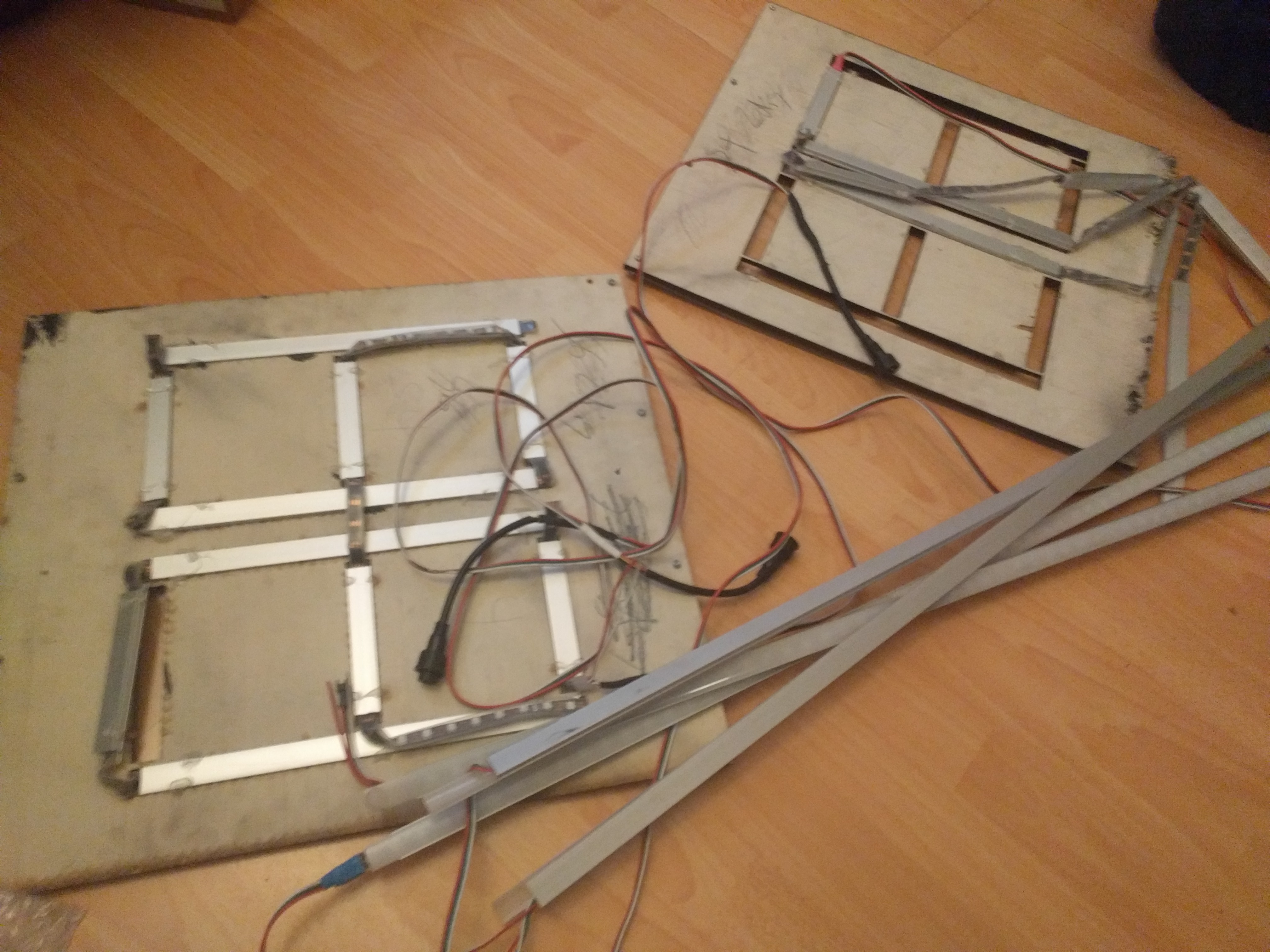
    The original aluminum backing had the LED strips hot glued on (!)  No wonder they were falling off...with dodgy wire repairs and cables everywhere.  At least I organized the cables before transport (and this pic):

    All this was replaced with a proper cut-to-size and elevated (for better diffusion) wood backing and 3D printed LED bracket holders.  I also used the 3D printed wire clamps I designed to provide much needed strain relief.  Then I cut wood spacers using nice scrapwood from a shelf I took out of my closet (dont tell my landlord! :P). 

     It was the perfect size.  Plus, I love to recycle when possible.  I reinforced the spacers and did a first pass with wood glue, before tapping and drilling it all together with proper hardware.  Note the absence of hot glue! :P

  • 3D Printed Lock Nuts

    CriptasticHacker07/27/2023 at 22:53 0 comments

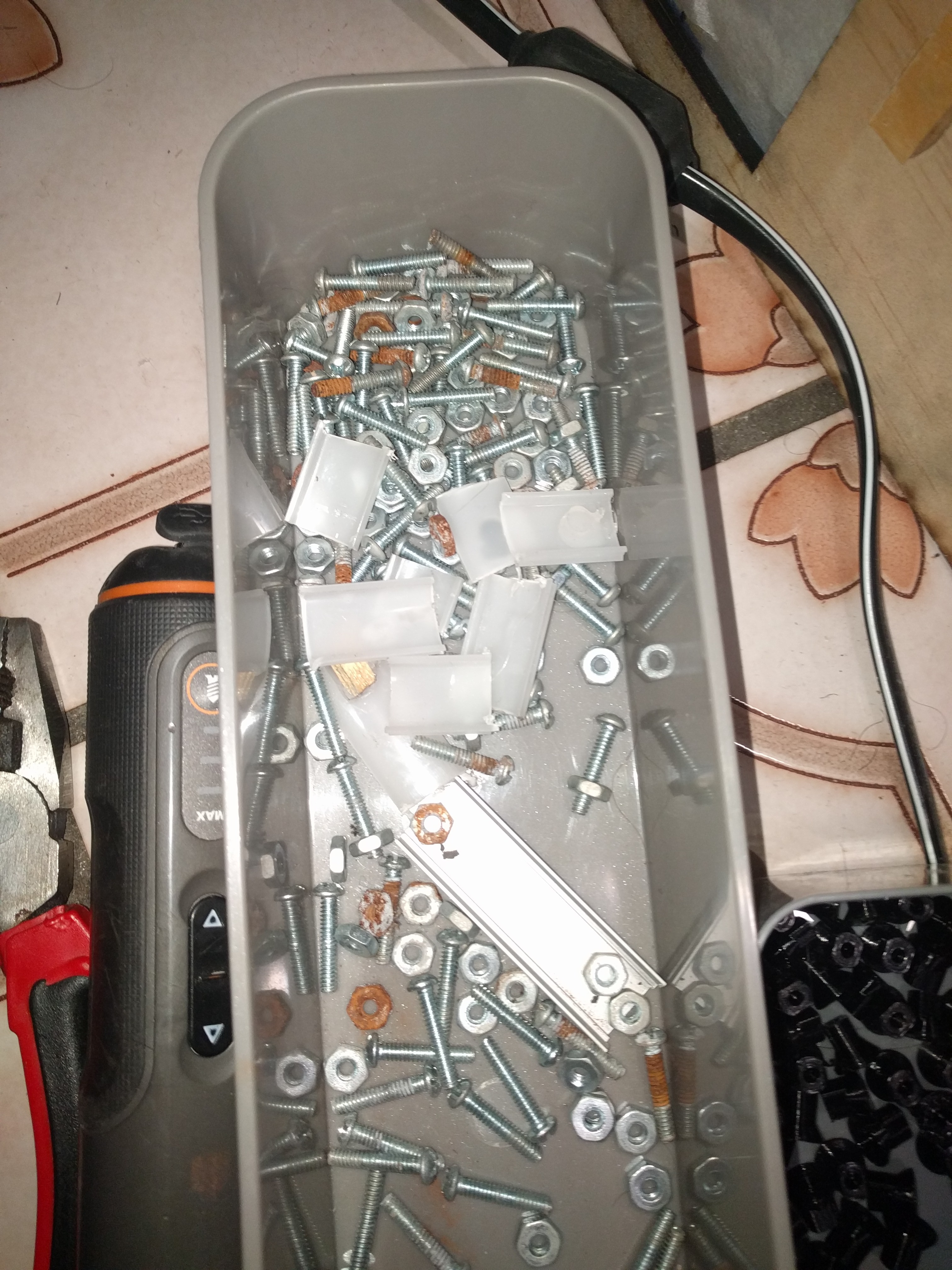
    Another big issue on arrival was the mounting hardware.  Long M4 size screws were sticking out all over the place, cutting and scratching things.  They were also rusted wth many loose nuts, and not even mounted in the same direction!

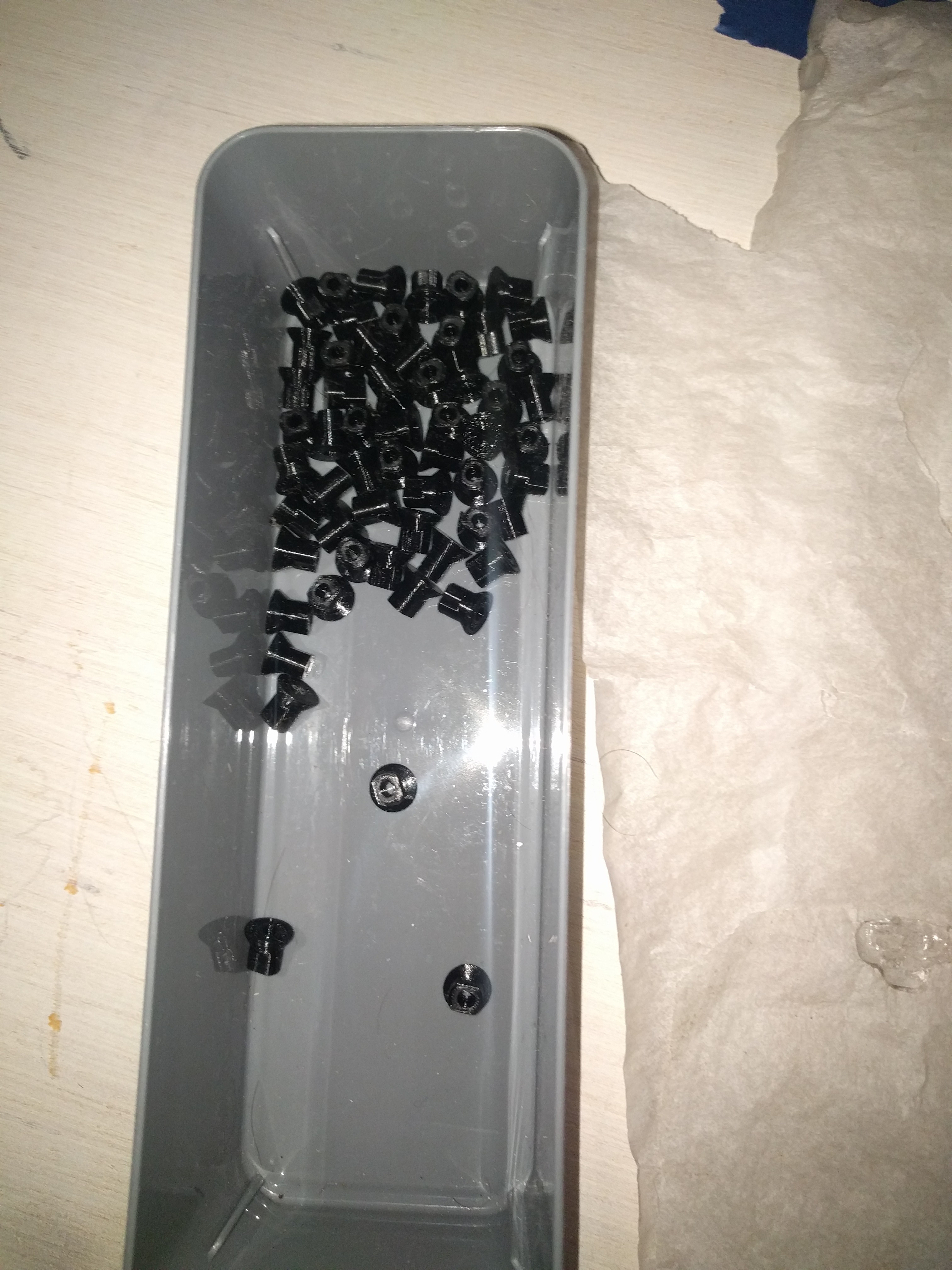
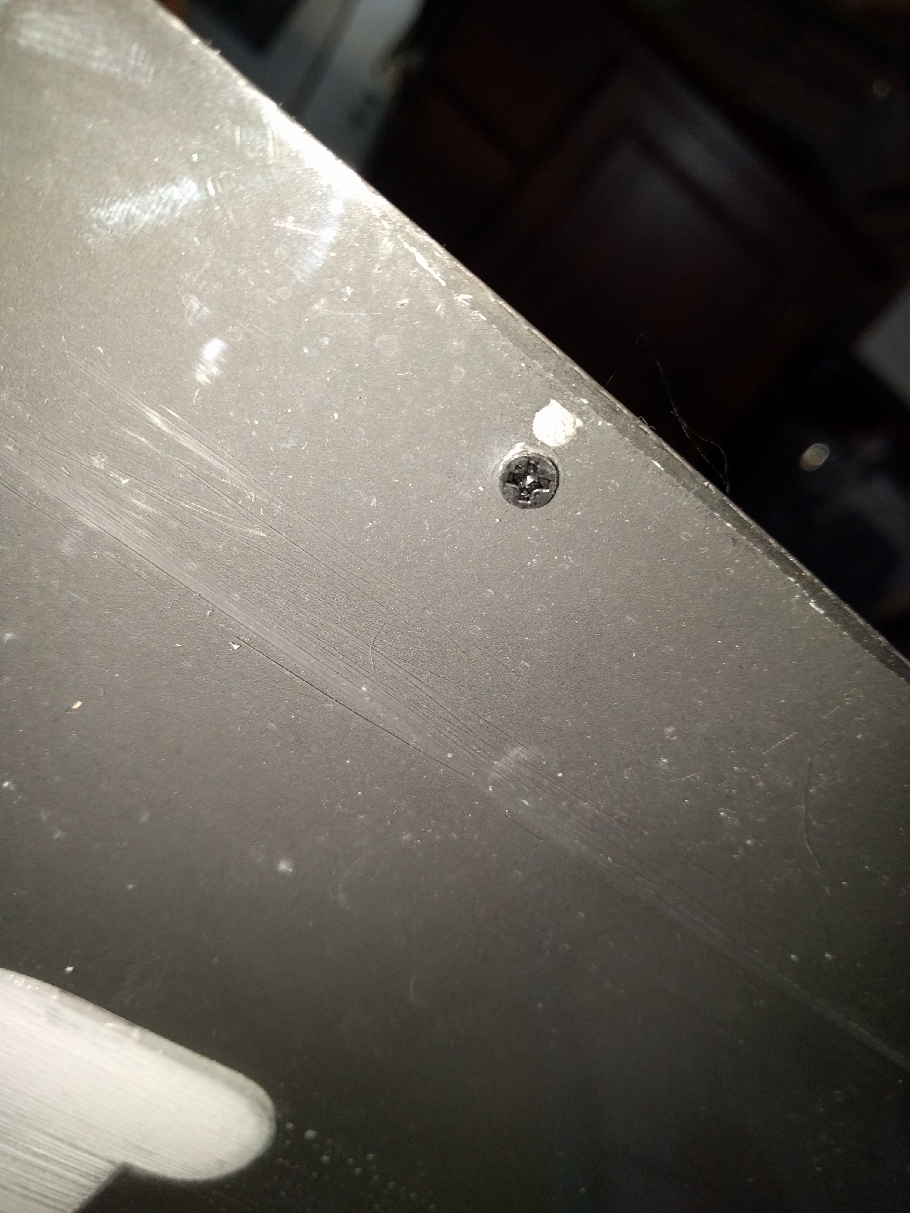
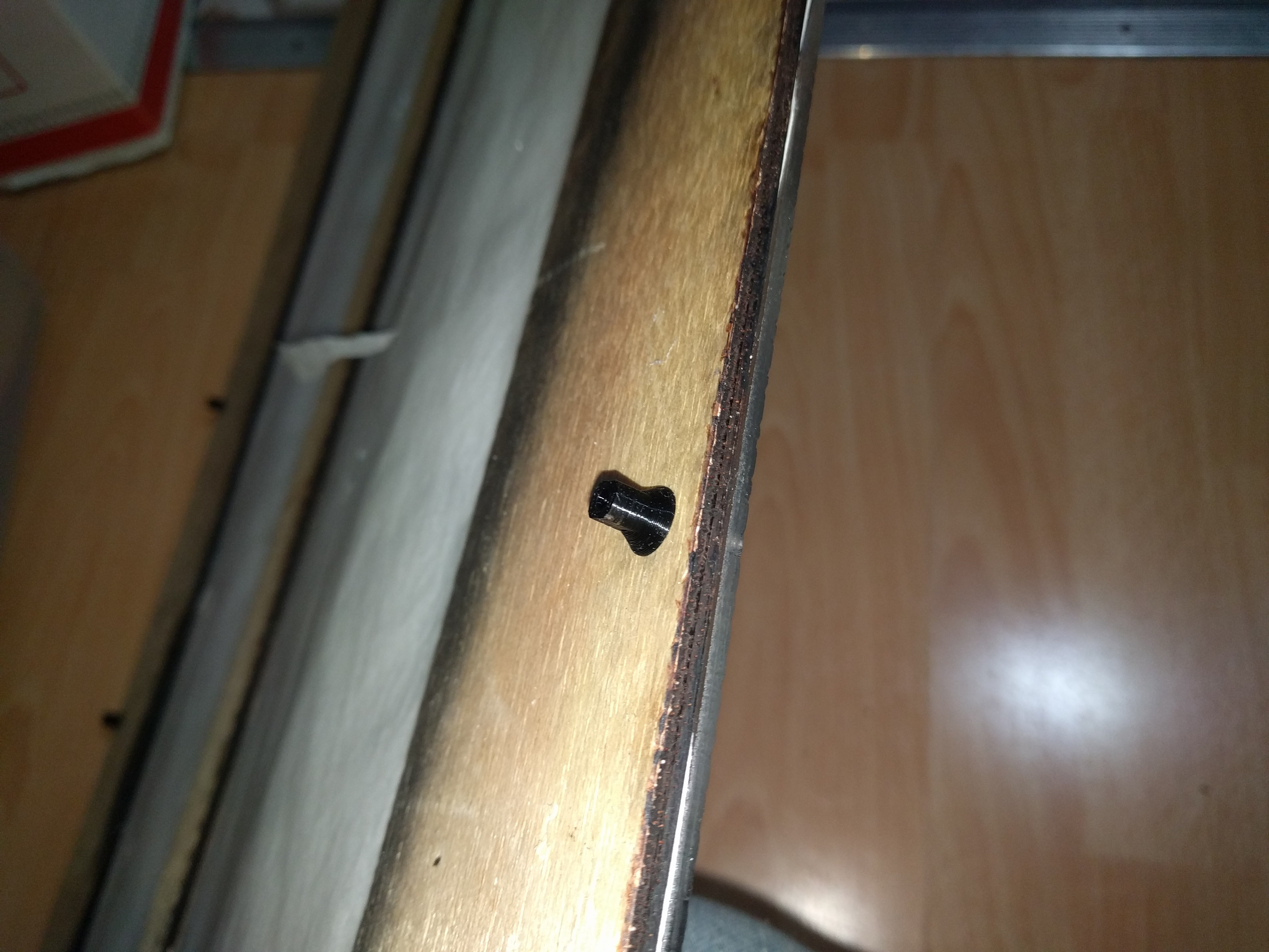
    These have got to go!  Instead, Ive designed and printed a nice PLA locknut.  I'm also using M3 Countersunk black screws, which will nicely match the black matte face of the panels.

    I designed the lock nuts with a built in large surface area to double as a washer, and long flat sides for easy gripping with pliers.  It made installs a breeze ^_^

    Back in Black!  Looking a lot better now.  This setup is also very easy to remove.  Since the lock nuts are self-tapped they are also shock resistant and make a much better contact with the plywood.  The countersunk screws are notw nearly flush with the plexi panel as well, making the outdoor box mounting a little easier.  

    And best of all, no more sharp metal to catch on me and scratch up the other plexi!

    [To be continued...]

  • Clip it!

    CriptasticHacker07/27/2023 at 22:25 0 comments

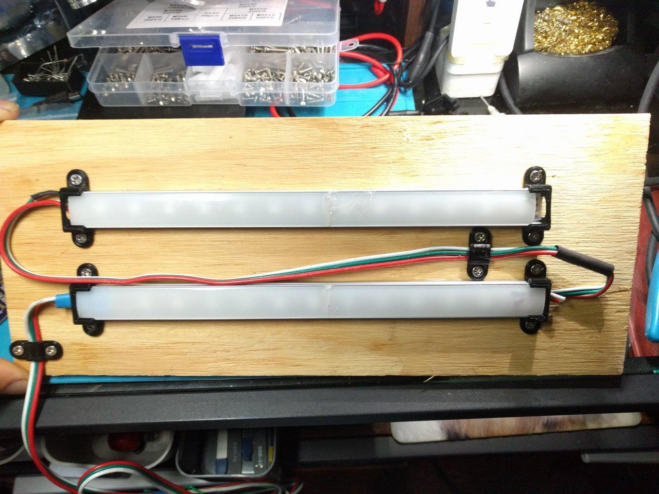
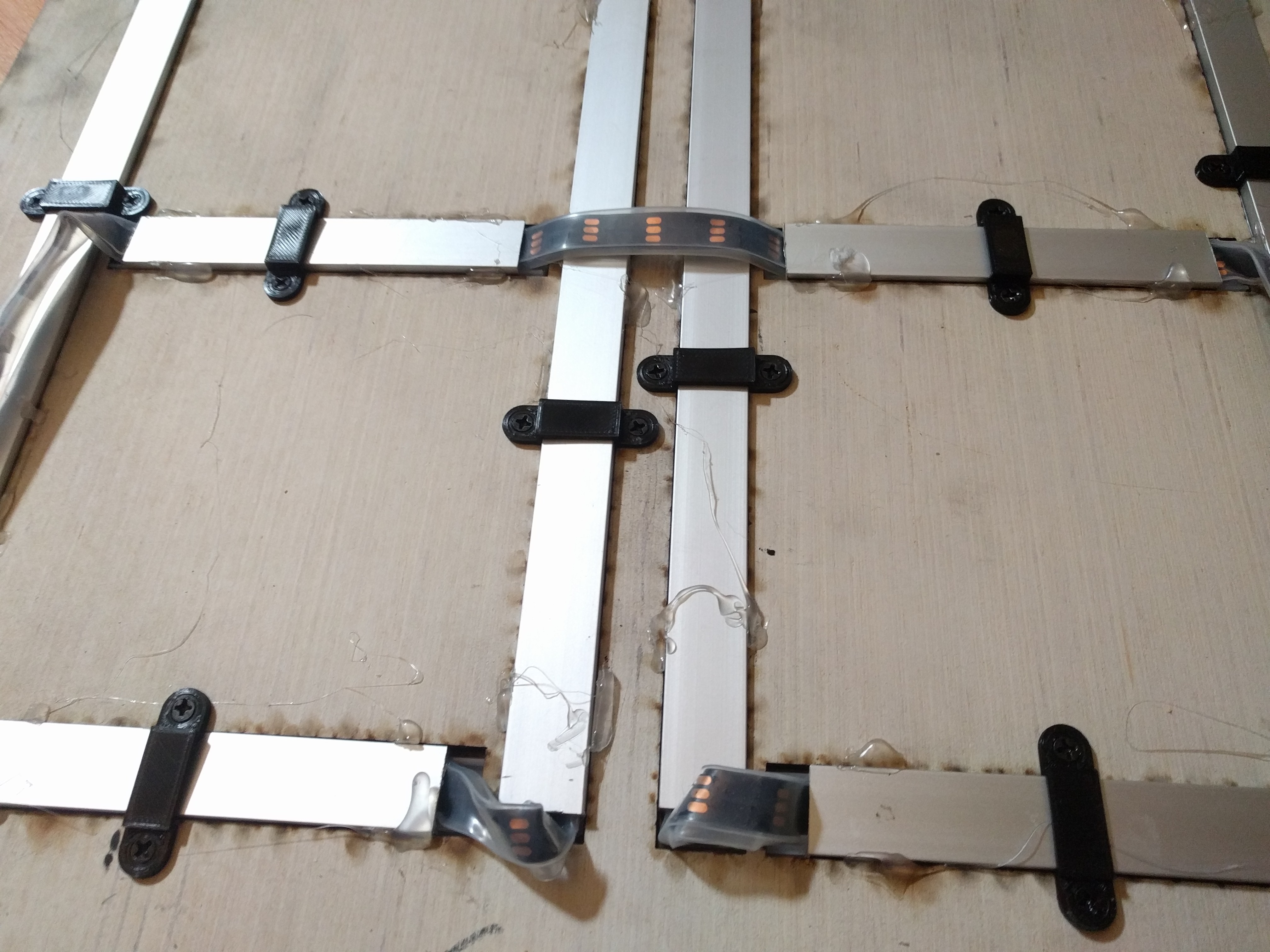
    One of the first orders of the day is to design and 3D print holder clips for the previous hot glued LEDs.  Hot glue wont hold up to the elements and temperature changes outdoors, so a mechanical support option is much preferred:

    How things were when they arrived:

    not looking so good! :O 

    Now let's do some TLC:

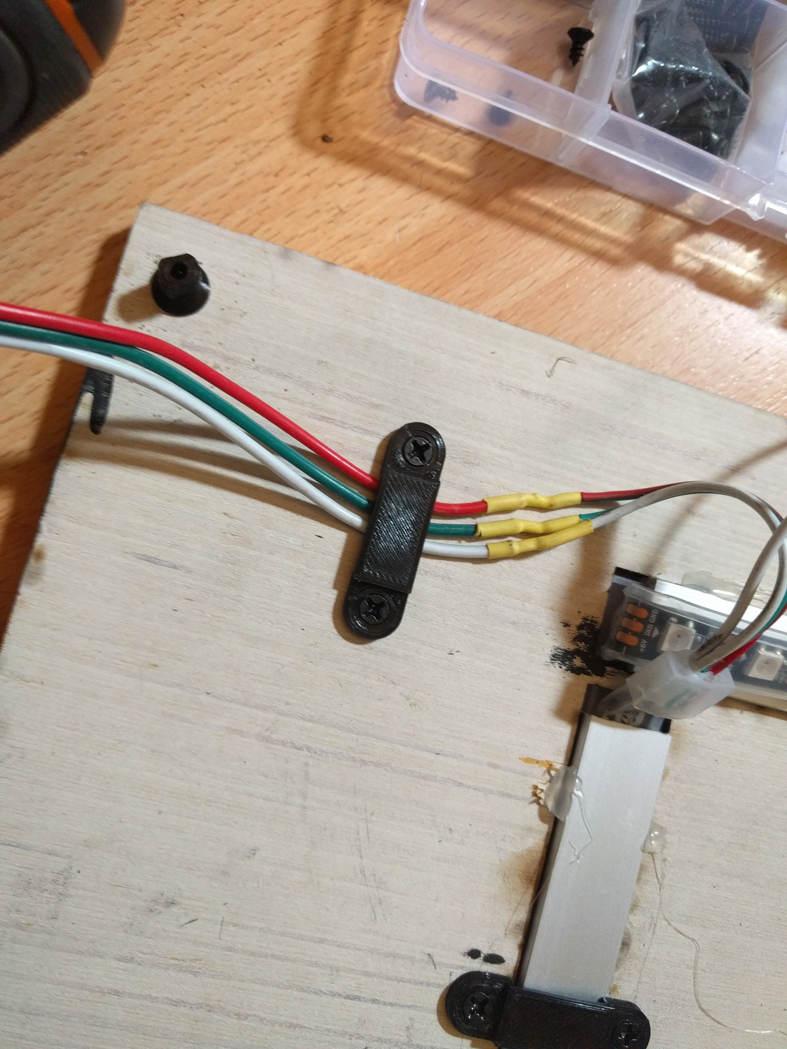
    ^ adding in some very essential strain relief.  Its not perfect (those heat shrink connections were certainly not my work!) but it ill do the job well for now


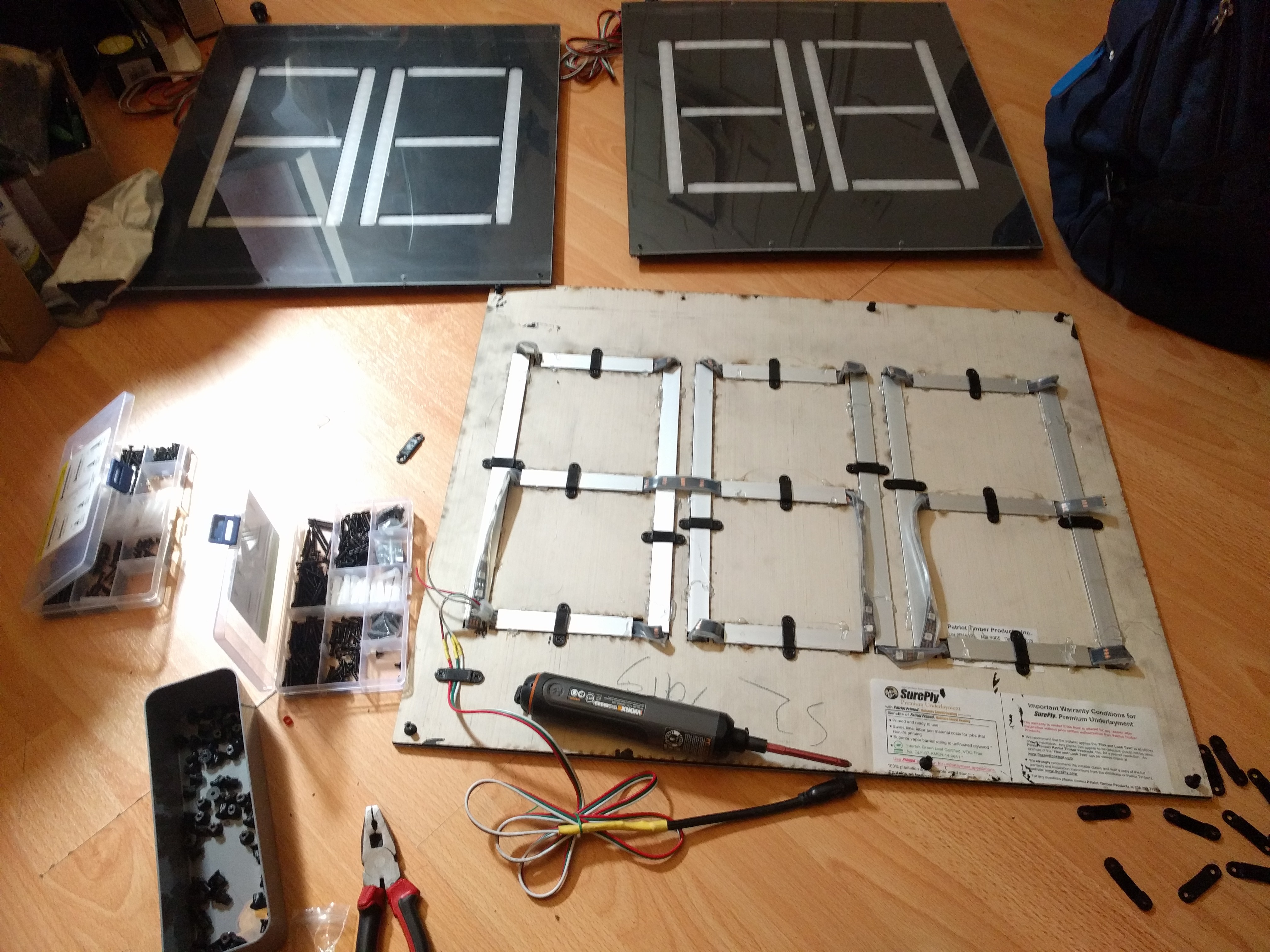
    ahh, now isnt that better?  Nice cozy LED digits all mounted correctly.  Youll notice the strips are sticking out in many places instead of being cut to match the slots - a choice made by the previous designer to save time I guess, and instead did not use those LEDs in the code.  A bit hacky, but it works I guess.


    [To be continued...]

  • Tackling the MCU / level shifter

    CriptasticHacker07/07/2023 at 18:07 0 comments

    Now that we have a somewhat safer power supply setup, and a way to attach things they don't fall off, it's time to dig into the microcontroller stuff.

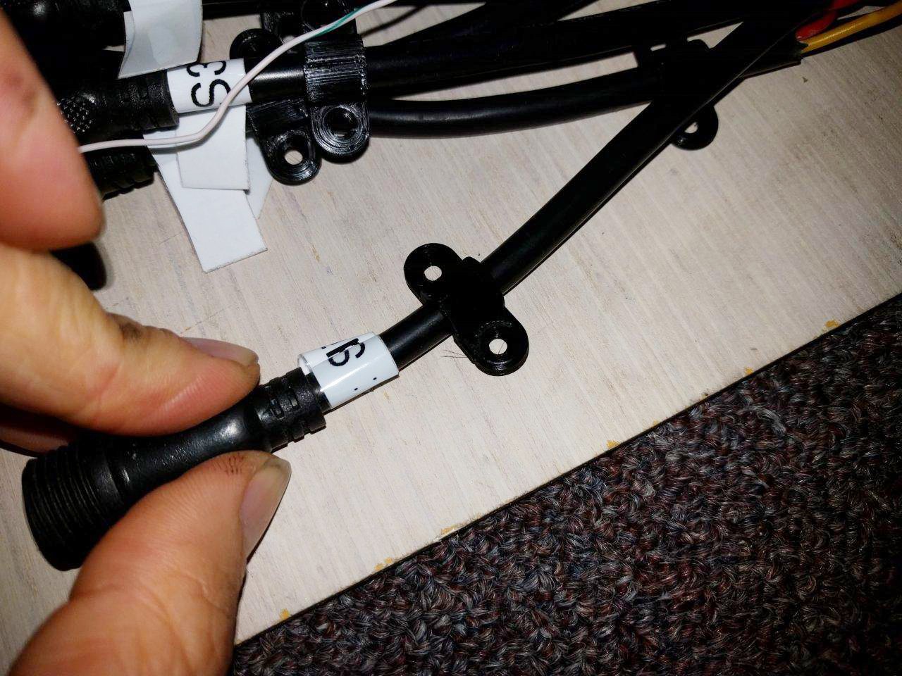
    The first thing I had to do was figure out the slight wiring mess.  Fortunately, the previous hacker labelled many wires.  So it was largely a matter of cross-referencing those markers to the Node32 (ESP32 module) pinout and the respective LED boards.  The sample test code helped a lot, since it had some info as well.

    After that, I assembled a perfboard module.  


    However, realizing how much time it was taking and also finding out I'd have *much* more lead time to finish this all, I opted to design a custom board.  

    These days I really shy away from "one-off" hand-soldered solutions, especially with an open source, reproducible design like this.  It makes greater sense to develop a board that can be shared with others, updated, and re-made if there's a failure of some kind.

    I searched for a "Node32" Eagle CAD footprint.  One came up, but as usual, it was a bit janky.  It had the wrong pin spacing and nothing was labelled.  The schematic symbol didn't label all GPIO pins, either. :/

    Time to make my own..

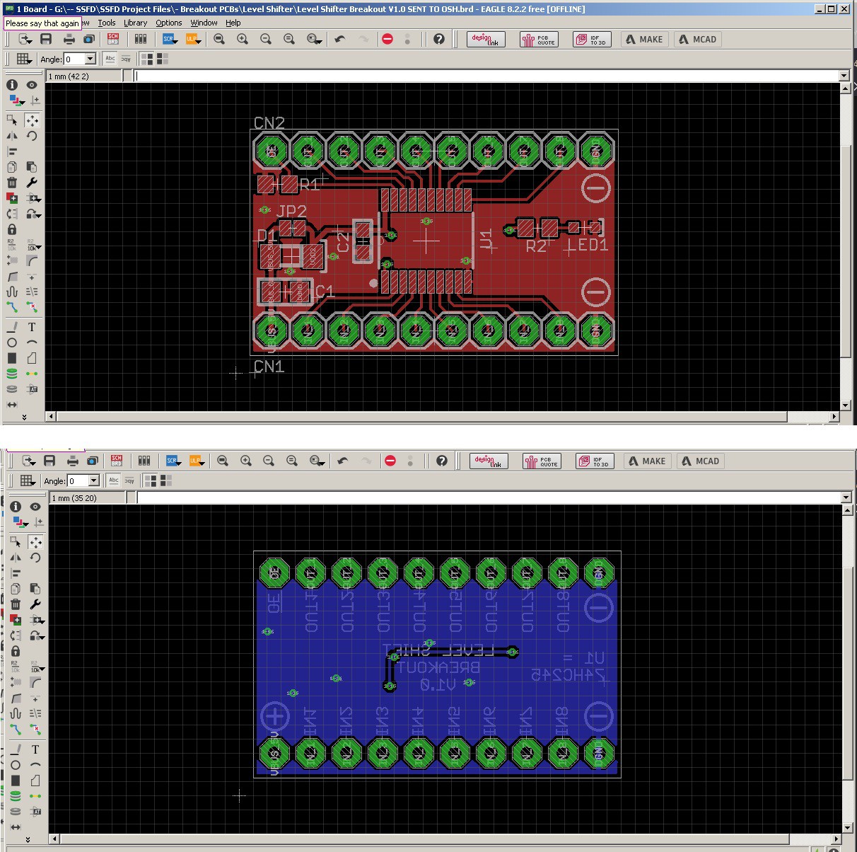
    I also designed a custom nice level shifter PCB for the 74HC245.  Confident this will work great when it gets back from the fab:

    Now it's onto making a combined board with the Node32.  Ideally with a disaply and control output, and the necessary pin header or Ethernet connector.  Some output plugs for voltage readings would be nice, too ;)


    [To be continued....]

  • Power Supply and 3D Printing clamps

    CriptasticHacker07/07/2023 at 17:52 0 comments

    My first step is to focus on safety and power reliability.  I don't actually want this thing to work if it's going to catch on fire, lol.
    so I'm replacing the giant open frame 5V 60A one with something more compact and fully enclosed.  

    At the time of this writing, this model is now out of stock, but it looks to be the same as the one here.  Heck, there's even one with more juice (15A) advertised for these very LEDs.  Strongly considering picking that one up...

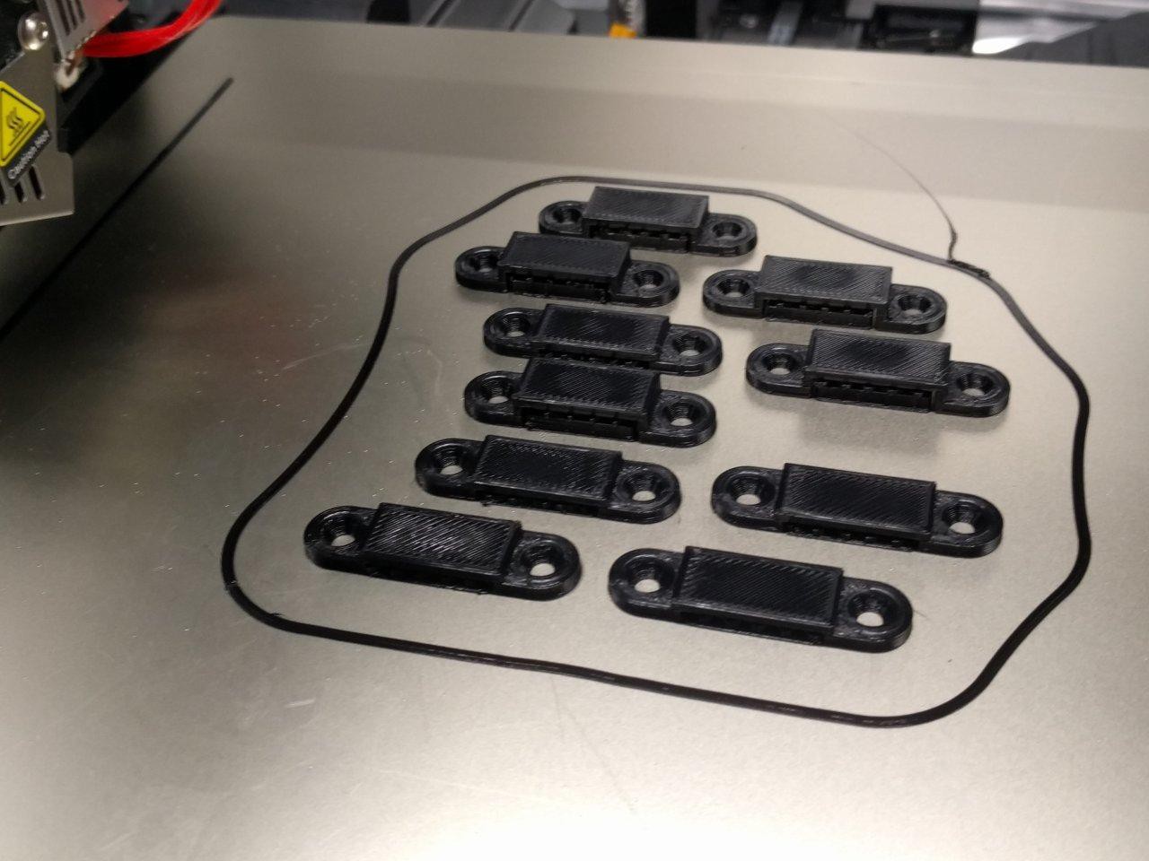
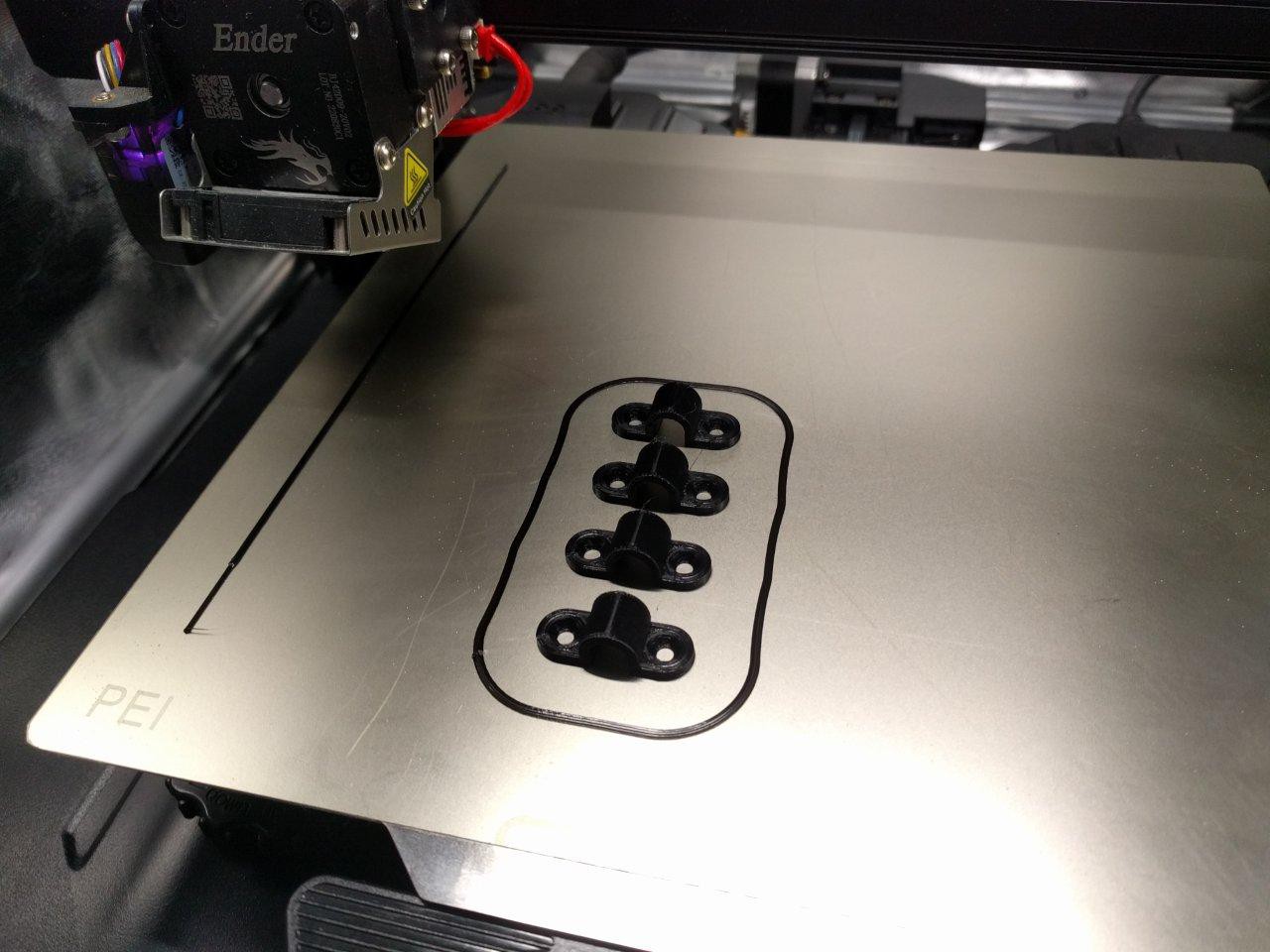
    After that, it was on to modeling and printing some legitimate clamps. I certainly don't trust holding everything on with hot glue, as is the current state I received it in.  Sure, I could use some kind of epoxy or foam double tape, but I'd like to have this be serviceable and have parts replaceable when needed.


    There are 3x clamps here for holding in the PSU, one small clamp model for holding down the individual board output connector cables, and a flat wider clap for holding down the LED strips.

    I made two wide clamp variants, 1 type that's 2mm tall and 1 type that's 4mm tall.  This is to accommodate the somewhat jerry rigged installation of LED strips which have differing protuding Z heights.

    The blue PSU clamp in the picture has an extra cutout for the power LED.

    Everything printed out great, and I'm confident these will be usable on a first iteration.  I did some minor tweaks to my countersunk M3 holecut model and it works perfect now :)

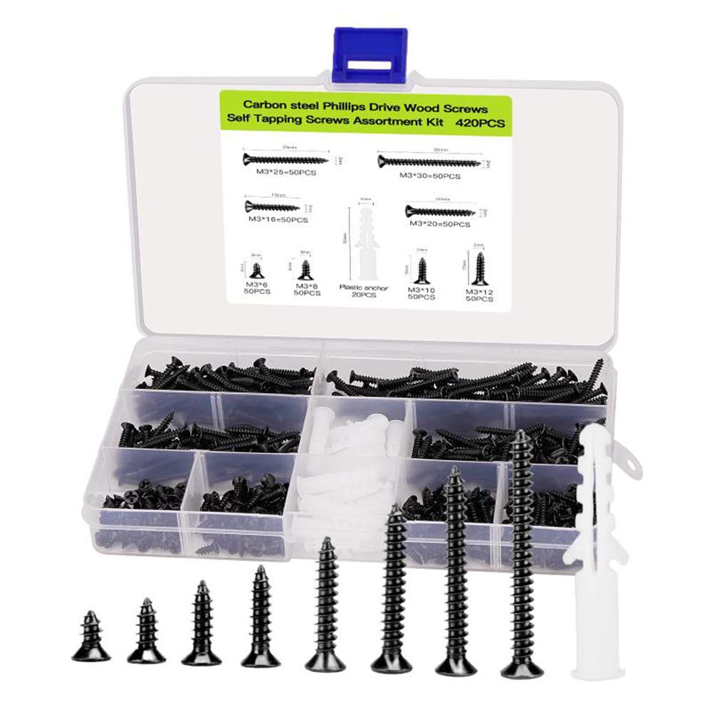
    They are all designed to work with these screws:

    Note, the models did not include the full AC power plug width, so some minor rotary drilling will be needed for two clamps.  no biggie.  I also need to sand / drill off the nubs underneath the power supply for a flush fit.  The radius for the corners fits perfectly at 6mm, using my trusty 3D printed fillet gauge from the wonderful @Matt_DatumCAD :)

    [To be continued...]

View all 10 project logs

Enjoy this project?

Share

Discussions

CriptasticHacker wrote 07/18/2023 at 05:32 point

all will become clear in time.  I just got the panels in hand and will show it all when I do more write ups.  Doing a lot of cleanup at the moment! :P
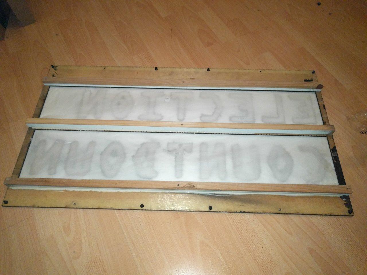
there are 9 panels - some have 2 digits, some have words.  its all LED strips.  Keep following, Ill post more soon :)
  Are you sure? yes | no

Thomas wrote 07/15/2023 at 16:37 point

Cool project! But what do the actual LEDs look like? Is each digit or number a discrete module?

  Are you sure? yes | no

CriptasticHacker wrote 01/02/2024 at 23:01 point

each panel has a long string of LEDs! WS2812s. It's hardcoded which digit segment is what LED position on the string.

  Are you sure? yes | no

Similar Projects

Does this project spark your interest?

Become a member to follow this project and never miss any updates