The computers I wanted to use this panel with are:
- the TX-0, one of the first transistorized computers, mid 1950s
- the PDP-1, a sort of successor to the TX-0, famous for Spacewar! ~1960
- the PDP-4, similar to PDP-1 but not the same. 1962
- the PDP-7, same architecture as the PDP-4, first machine to run UNIX. 1965
- possibly the PDP-9 and -15, same architecture again, also (briefly) ran UNIX
Of course an 18 bit panel is also compatible with smaller word sizes. My particular interest here is the
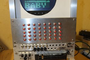
- Whirlwind I, the ancestor of all of the above. Probably the first computer that was designed for high reliability, real-time and interactive use, being a piece of and controlling a system rather than doing pure number crunching, and as such the spiritual grand-daddy of the modern microcontroller. Started 1947, in serious operation by about 1951
Hardware
The general design is the same as that of Oscar's PiDPs. The main difference is that this panel has columns of 18 bits (instead of 12): 3x18 LEDs and 2x18 switches/buttons. To drive the LEDs, one LED row is driven high and the 18 column pins are driven low for every LED in that should be on. To read the switches, one switch row is driven low and the column pins are sampled. By cycling through the rows, all LEDs and be set and all switches be read.
This was my first real attempt to use KiCad or build any sort of circuit in hardware. After a day of designing and layouting the board I got some feedback and made some fixes and adjustments, then ordered my first ever batch of PCBs from JLCPCB!! A week later they arrived and the first board was soldered the next day. It worked immediately, success!
Aesthetically I was inspired by this tiny PDP-8 front panel.
The pinout is compatible with the RaspberryPi GPIO header. This makes it compatible with widely available hardware and easy to use. However, eventually I also want to hook up FPGAs for more timing-accurate simulations.
TX-0 simulation
My first target for a computer to simulate was the TX-0. Since I had already implemented most of it in verilog I decided to use verilator to get something up and running easily.
This is not the place to discuss the TX-0 and its evolution over the years in depth. You can watch my little Youtube series to learn more about it. The incarnation I have simulated so far is the original one with 64kw memory and no new instructions.
After deciding which switches, buttons and LEDs would have which exact functions (remember this is a generic panel not specifically designed for the TX-0), I wrote some verilog and C(++ i guess, verilator...) and did some simple tests like clearing the accumulator, examining memory and so on. Next I'd have to run some actual code.
To get some interaction I implemented the Flexowriter interface. This allowed me to actually run UT3, short for utility tape 3, an early interactive debugger and the progenitor of DDT.
The real fun starts with graphics so I also implemented the display interface. Because simulating the screen is a bit demanding I'm just sending coordinates of the points that are to be intensified over the network and do the heavy lifting on my laptop. The display is based on the wonderful PDP-1 simulations by Norbert Landsteiner. With the display working I could finally behold the beauty of the Minsky circle which I had previously written for the TX-0.
PDP-1 simulation
Even though there is still a lot that could be done on the TX-0 I decided to tackle the PDP-1 next. With a lot of the framework already in place I got my verilog code to show signs of life after only a few hours. Getting the PDP-1 functional enough to run something like the minskytron or spacewar is currently WIP.
PDP-9 simulation
I sent one panel to Lars Brinkhoff who expressed interested in doing an accurate simulation of the PDP-9. The 9 is a slightly weird machine because it uses microcode for part of the logic. A working PDP-9 should be compatible with the original UNIX, exciting!
... Read more »


 dave
dave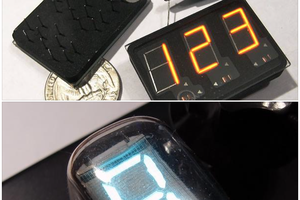
 Ken Yap
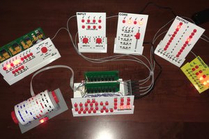
 Michael Gardi
I have soldered a PCB right now, and follow the Instructions from here : https://github.com/aap/blincolnlights, but i have the same issue like Andy. I use a fresh installed Raspberry 2.
When i start mkptyfl from the tools directory i have a wonderful blank screen :(
Do you any suggestions ?