 Mitsuru Yamada
1. Concept
As a practical application of my PERSEUS-9 computer for astronomical observation, I decided to create a hardware and software system to display the celestial coordinate system of an equatorial mount. This computer is not suited to perform a large amount of processing at high speed because of its 1970s processing speed. Therefore, instead of controlling the mount from the computer side, the PERSEUS-9 reads and displays control status of the controller. From the button operation of the hand controller to the counting of motor drive and drive pulses, the system is configured with homemade hardware MCT-6. The count values are converted to angle values in right ascension (R.A.) and declination (Dec.) by CI-2, a homemade floating-point interpreter for PERSEUS-9, and displayed in real time. No automatic GoTo action or polar axis correction from the computer side is performed. Figure 1 shows the MCT-6 and the computer PERSEUS-9, and Fig. 2 shows the homemade equatorial mount.
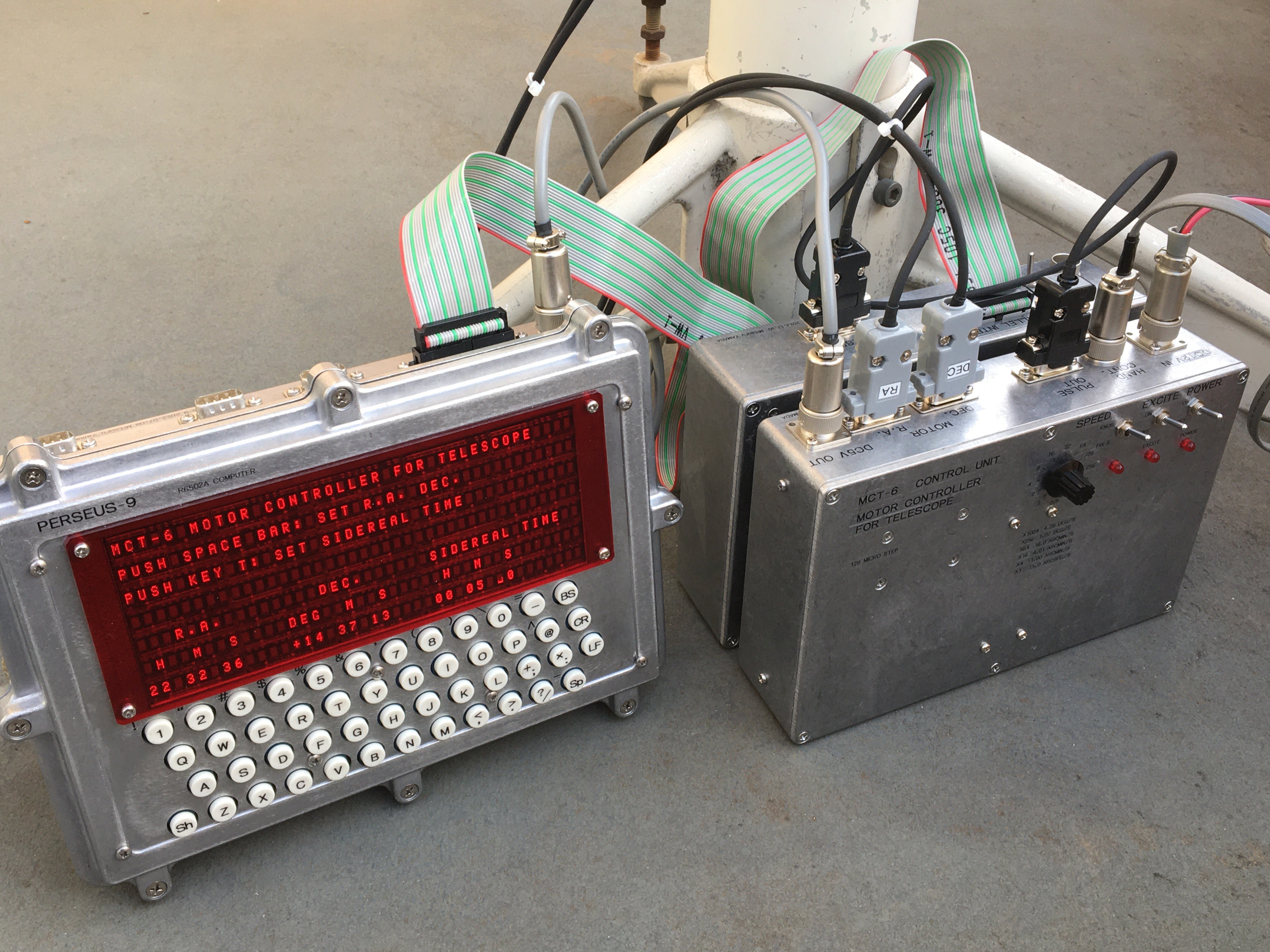
Fig. 1 MCT-6 the telescope mount controller and PERSEUS-9.
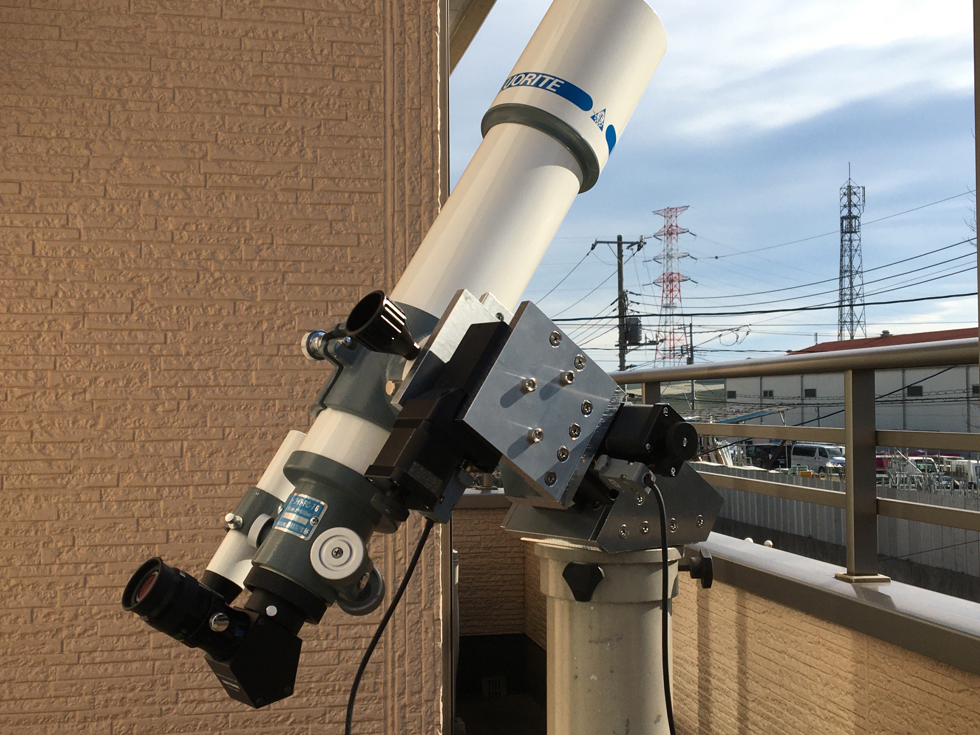
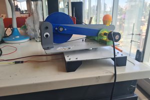
Fig.2 Homemade telescope equatorial mount with a 7.6cm refractor optical tube.
2. Equatorial mount
Another major challenge for me in this project was to build an equatorial mount that would be practical for my own visual observations. An equatorial mount has two orthogonal axes, one of which is the R.A. axis, which is parallel to the earth's axis of rotation. The R.A. axis rotates once every 24 hours, 56 minutes, and 4 seconds, which means that the telescope can automatically track a fixed star. This is known as tracking diurnal motion. Assuming that the telescope's observation resolution is about 1 arcsecond in angle, the vibration during tracking must be kept to less than a fraction of that in order for the star not to appear shaky. On the other hand, if the telescope is moved in a different direction to slew another object, the speed must be several hundred times higher than the tracking speed.
There are difficulties in satisfying these two conditions simultaneously. For example, if such a speed change is achieved using a normal stepper motor drive system, the step period during diurnal motion tracking will be about once per second of time or once every 15 seconds of angle, and the tracking image will appear to shake violently. Therefore, if a micro-step drive method that divides the stepper motor steps into smaller steps is used, it is possible to perform fine driving of several tens to several hundreds of steps per second even during tracking. In this way, a drive system with sufficiently reduced vibration is generally constructed.
It has also been difficult for me to prepare mechanical elements such as shafts, bearings, and worm gears that can withstand a certain amount of moment. So this time, I decided to see if I could solve this problem by using a commercially available motorized rotary stage. This motorized rotary stage is used for optical experiments and industrial applications and is expensive, but recently I found that it is available at a relatively low price through a certain mail-order site. Figure 3 shows the appearance of the motorized rotary stage used. This motorized rotary stage has a 60 mm diameter rotating part, and a 200 P/R stepper motor directly connected to a 90:1 worm gear. Both sides of the stage can be connected to other structures with M5 and M6 bolts.
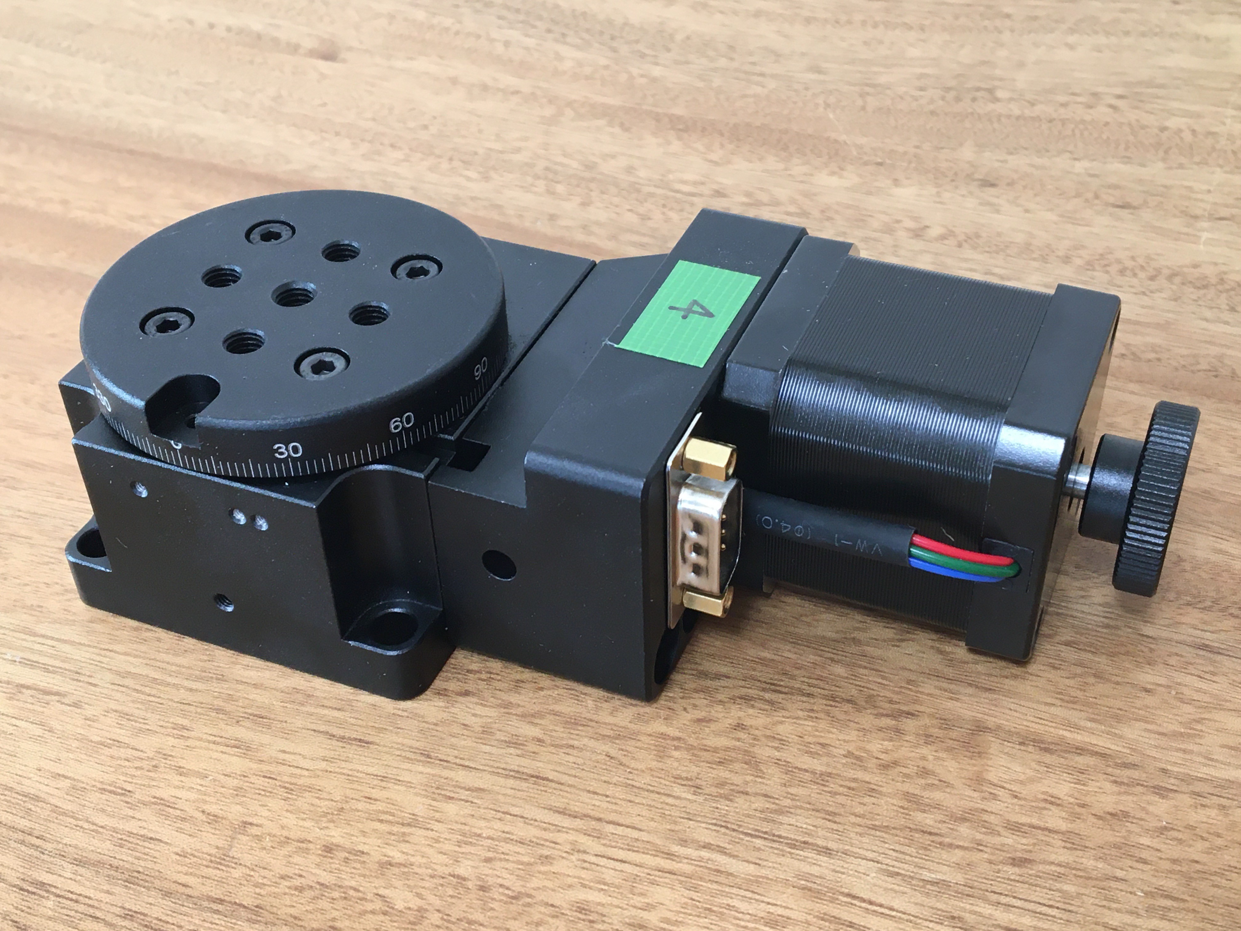
Fig. 3 Motorized rotary stage Y200RA60.
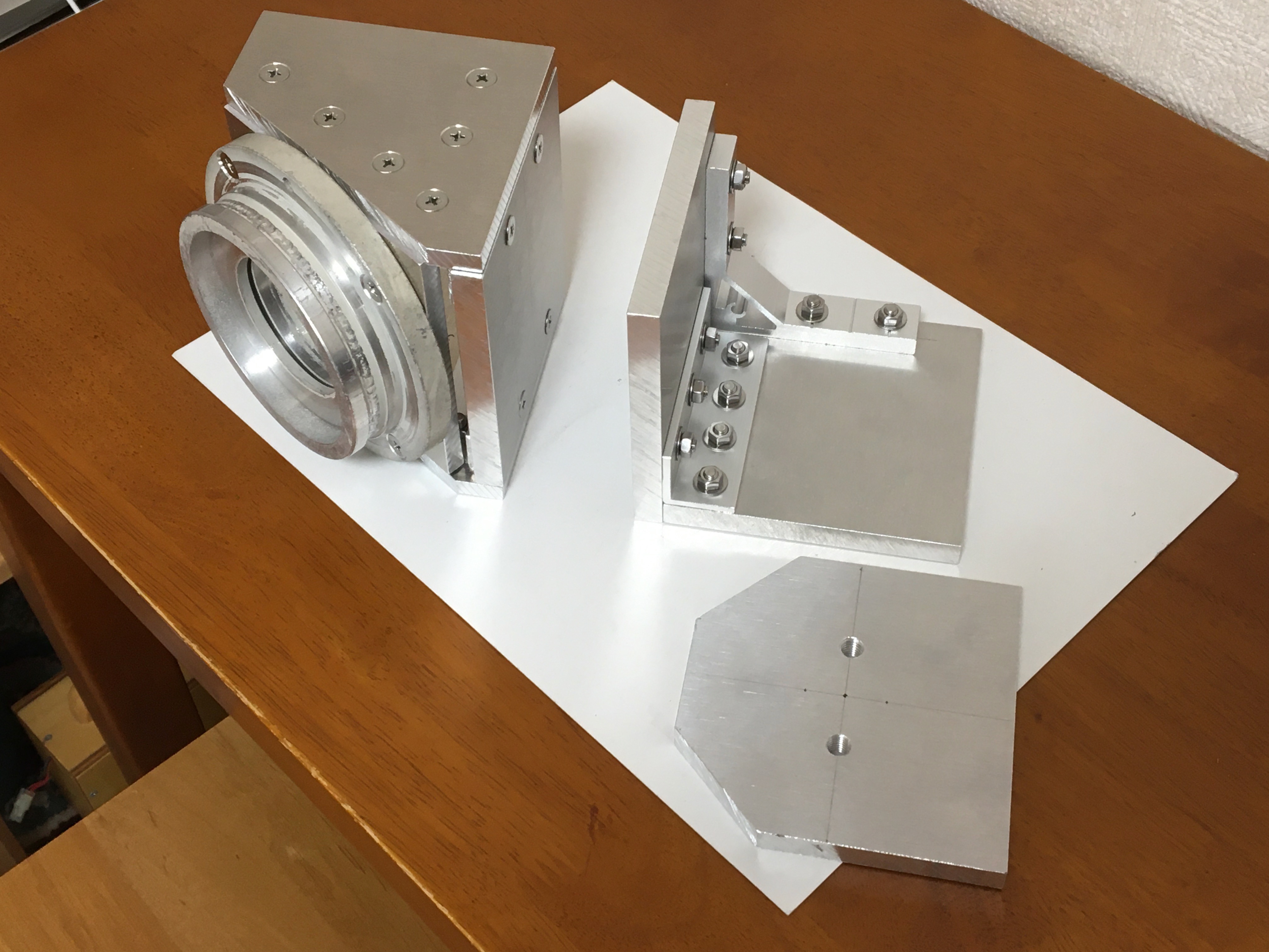
The appearance of the self-made equatorial mount is shown in Fig. 4. The structures on the equatorial mount other than the rotation stage were made of 100mm x 100mm, 10mm and 7mm thick aluminum materials that were machined and used. On top of the pillar connection body, the rotation stage of the R.A. axis is fixed to the face of the aluminum material, which is assembled to be perpendicular to the latitude value. On the rotary stage of R.A. upper surface, an L-shaped...
Read more »

 Antonio Lopez
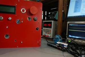
Is the purpose of this project to avoid using a laptop with auto guiding software? Why not control the motors with a more modern microcontroller, such as Arduino or Raspberry Pi? Or are you repurposing old hardware (which is awesome, BTW)? I'm just trying to understand the reason behind why you used the Perseus 9.