0%
0%
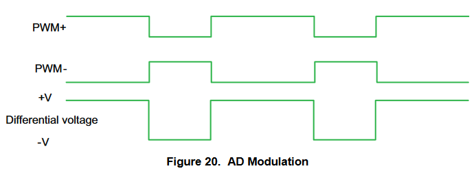
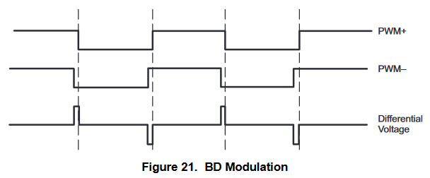
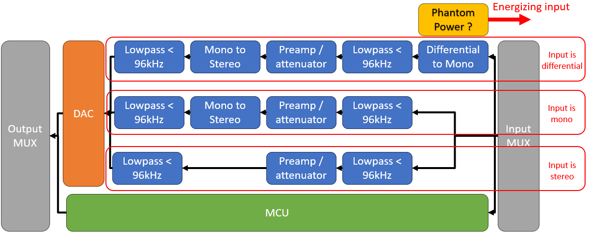
Digital Audio Mixer w/ Filters & Multiple USB I/O
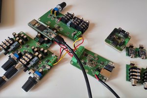
Using FPGAs and MCUs to build my dream audio setup
 MS-Dzo
Become a Hackaday.io member
Already have an account? Log in.
Just one more thing
To make the experience fit your profile, pick a username and tell us what interests you.
Pick an awesome username
hackaday.io/
Your profile's URL: hackaday.io/username. Max 25 alphanumeric characters.
Pick a few interests
Projects that share your interests
People that share your interests
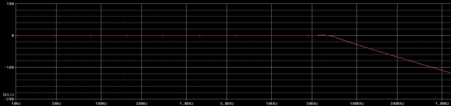 As for the ripple, it should be perfectly inaudible at 20KHz since it's only -0.007dB !
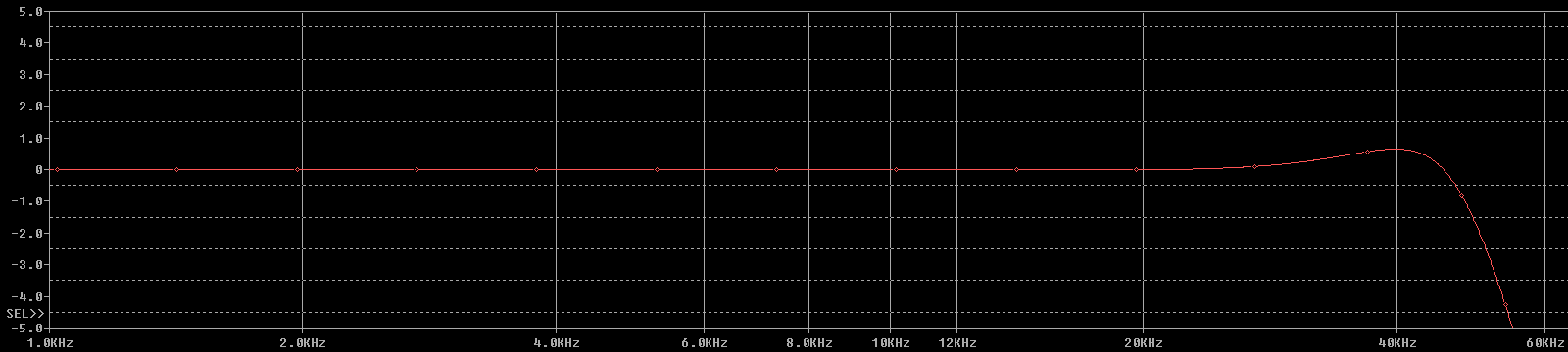 Turns out having a whole semester about butterworth and chebyshev did prove useful after all, uh.
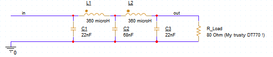
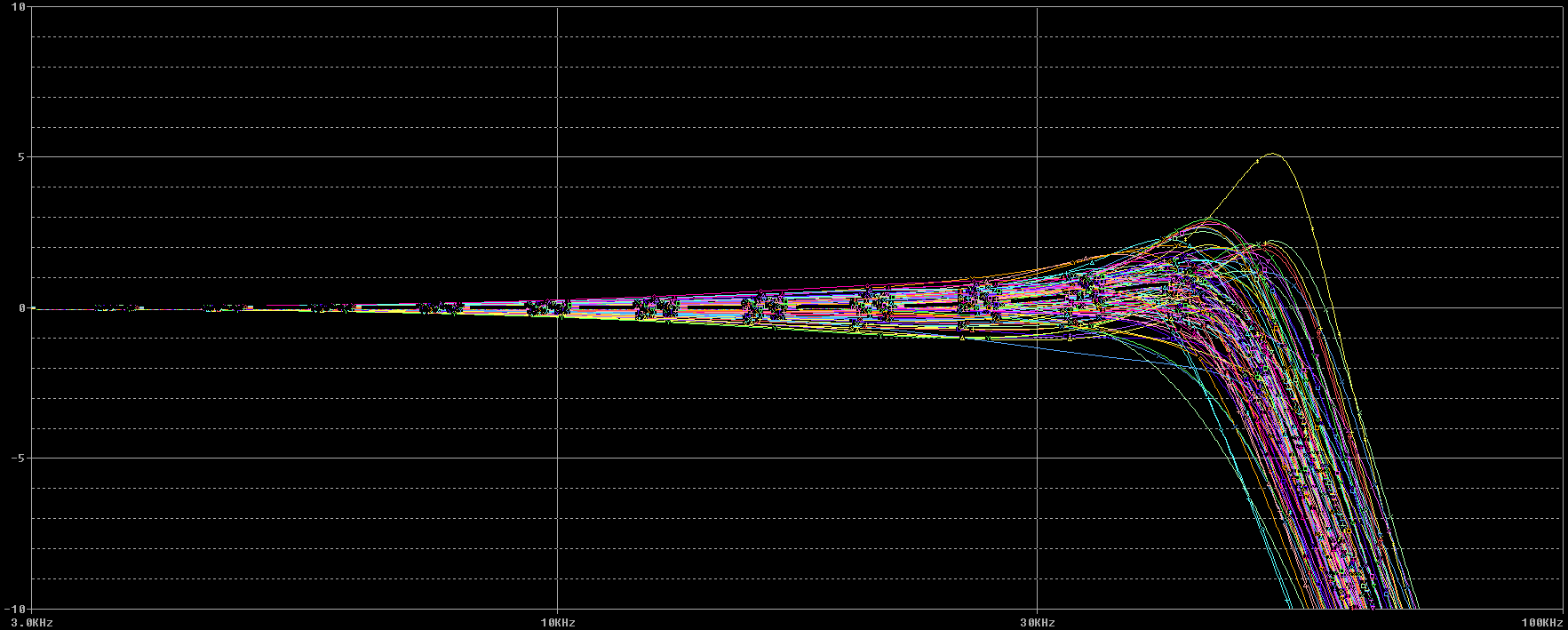
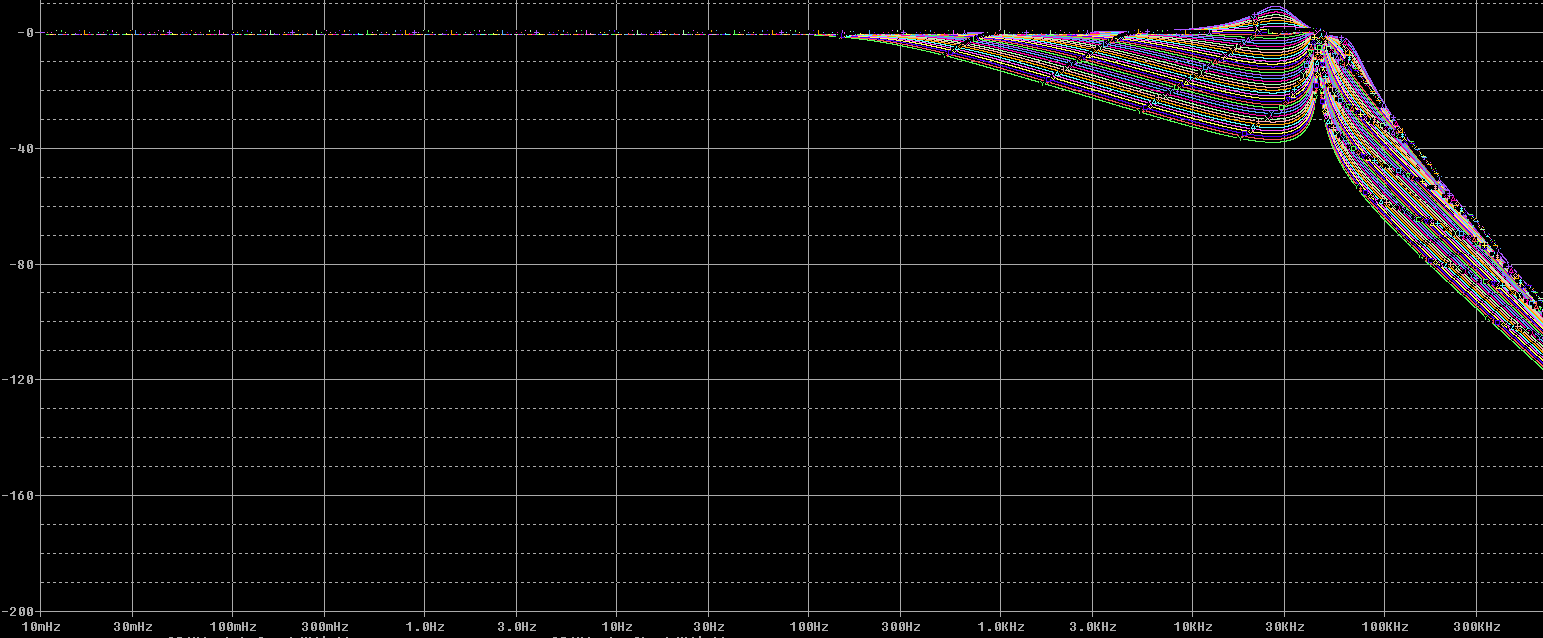 and, just to test something, here's a second order LC low pass filter response for an impedance varying between 1Ω and 1kΩ
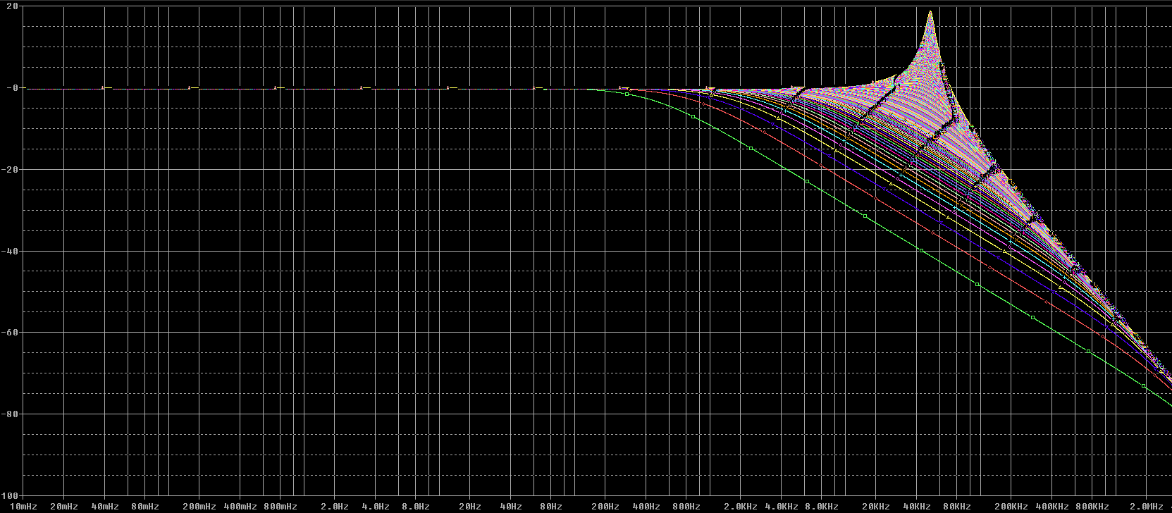
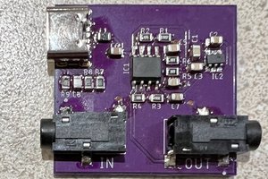
 Voila ! a DAC.

 Nick Sayer
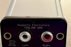
 Michele Perla
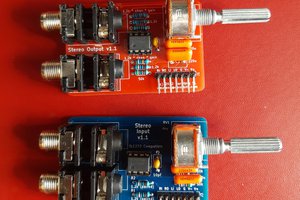
 David Moreno Montero