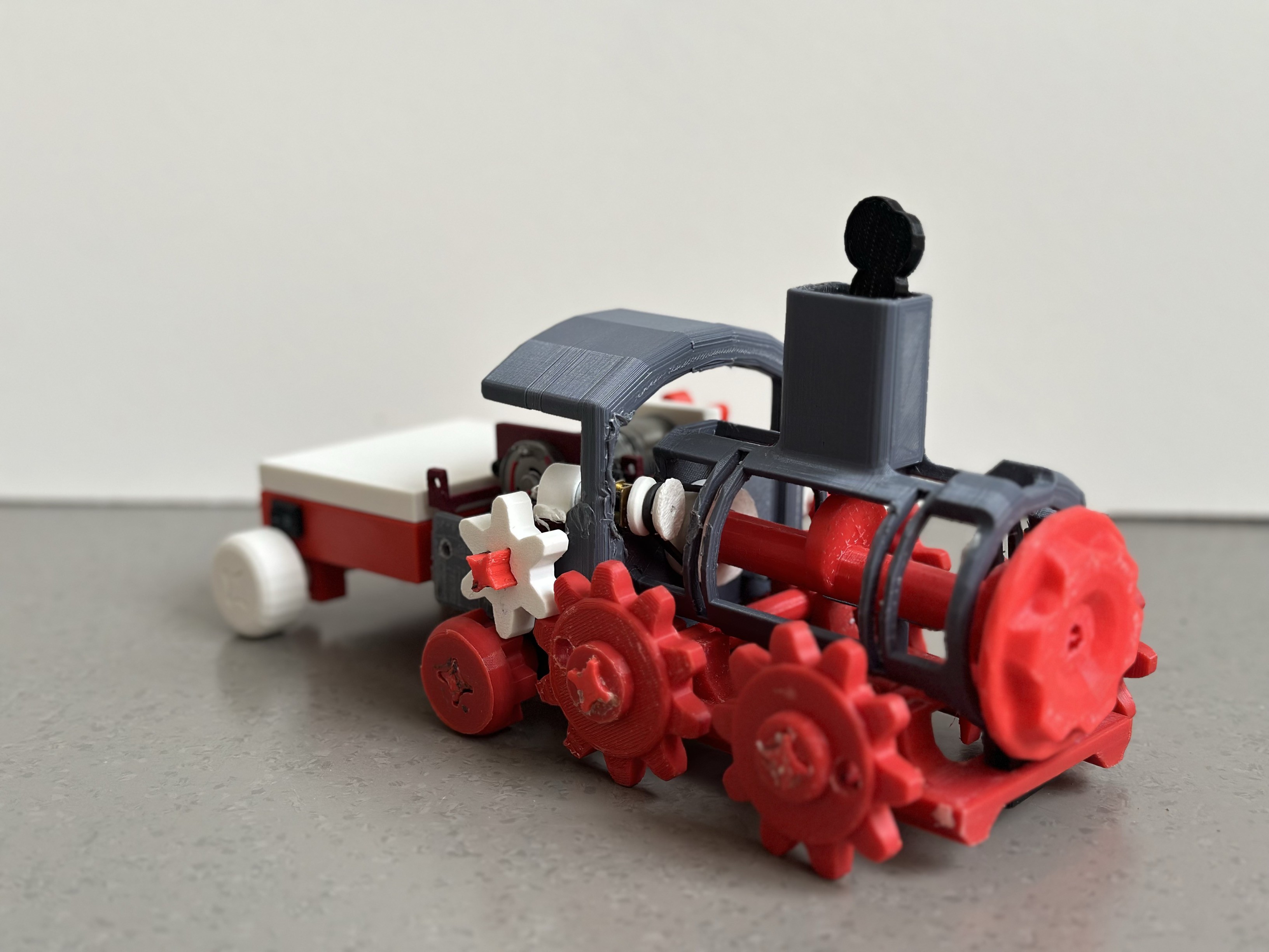
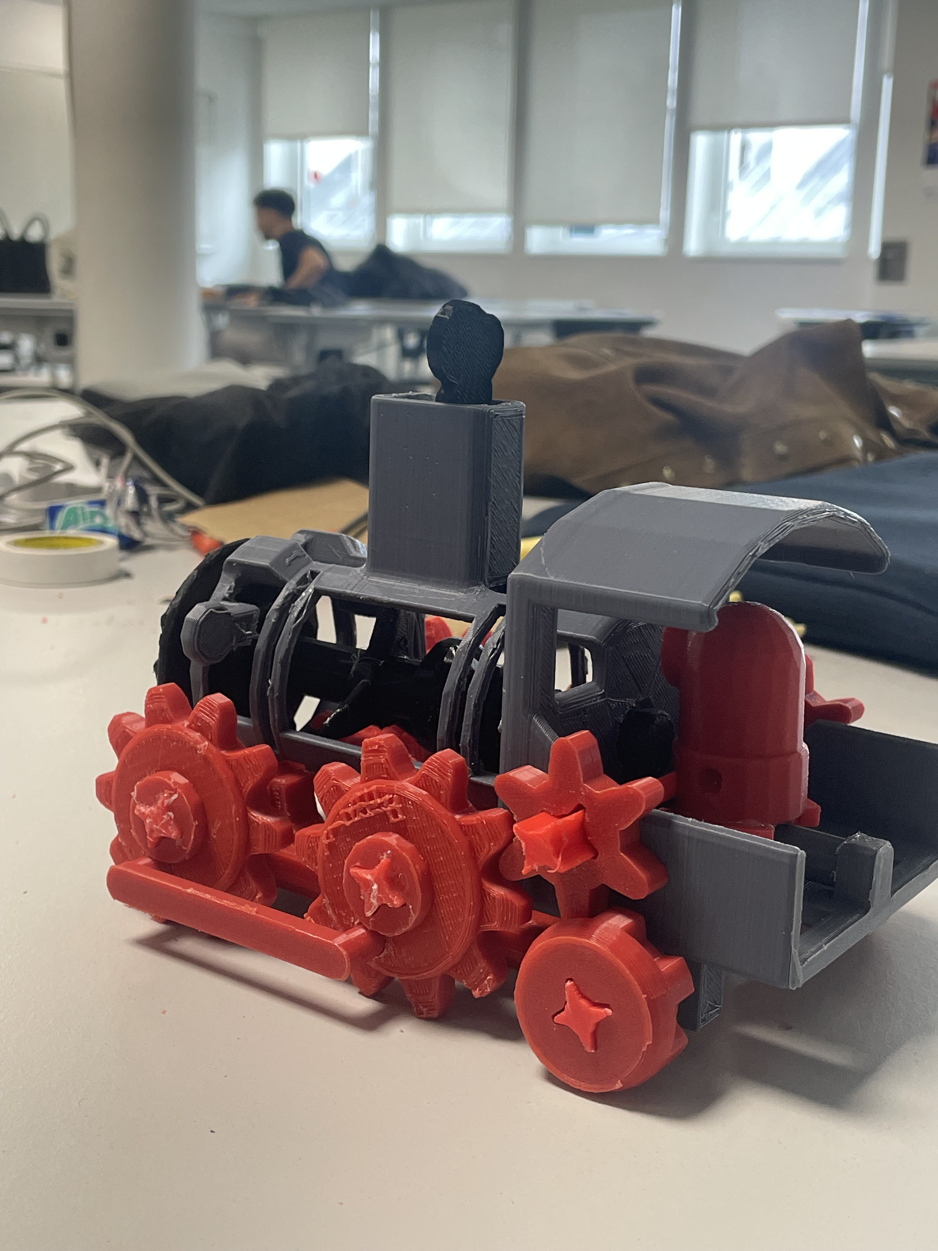
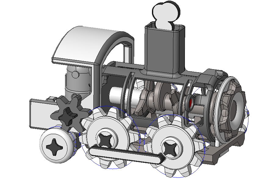
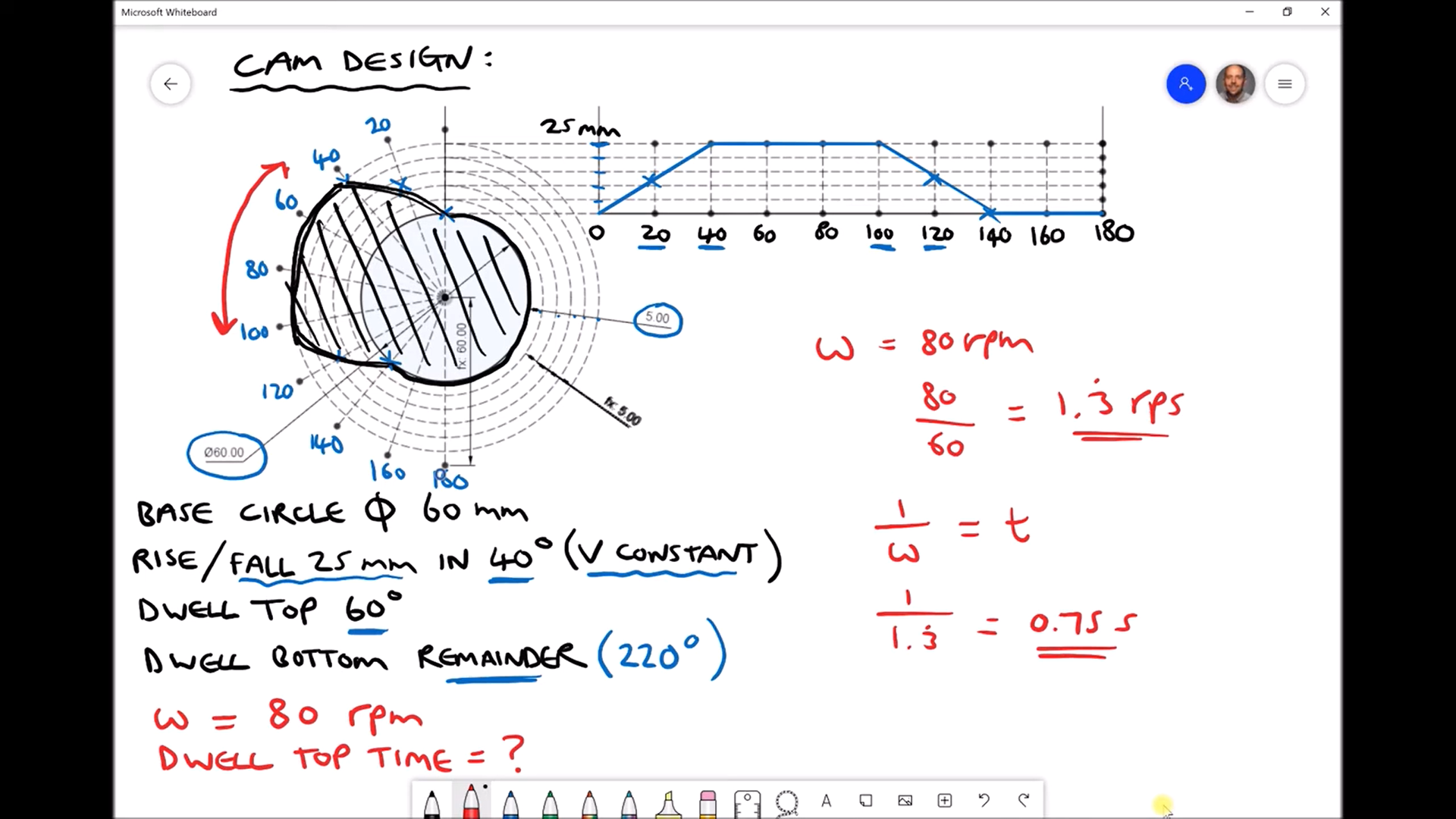
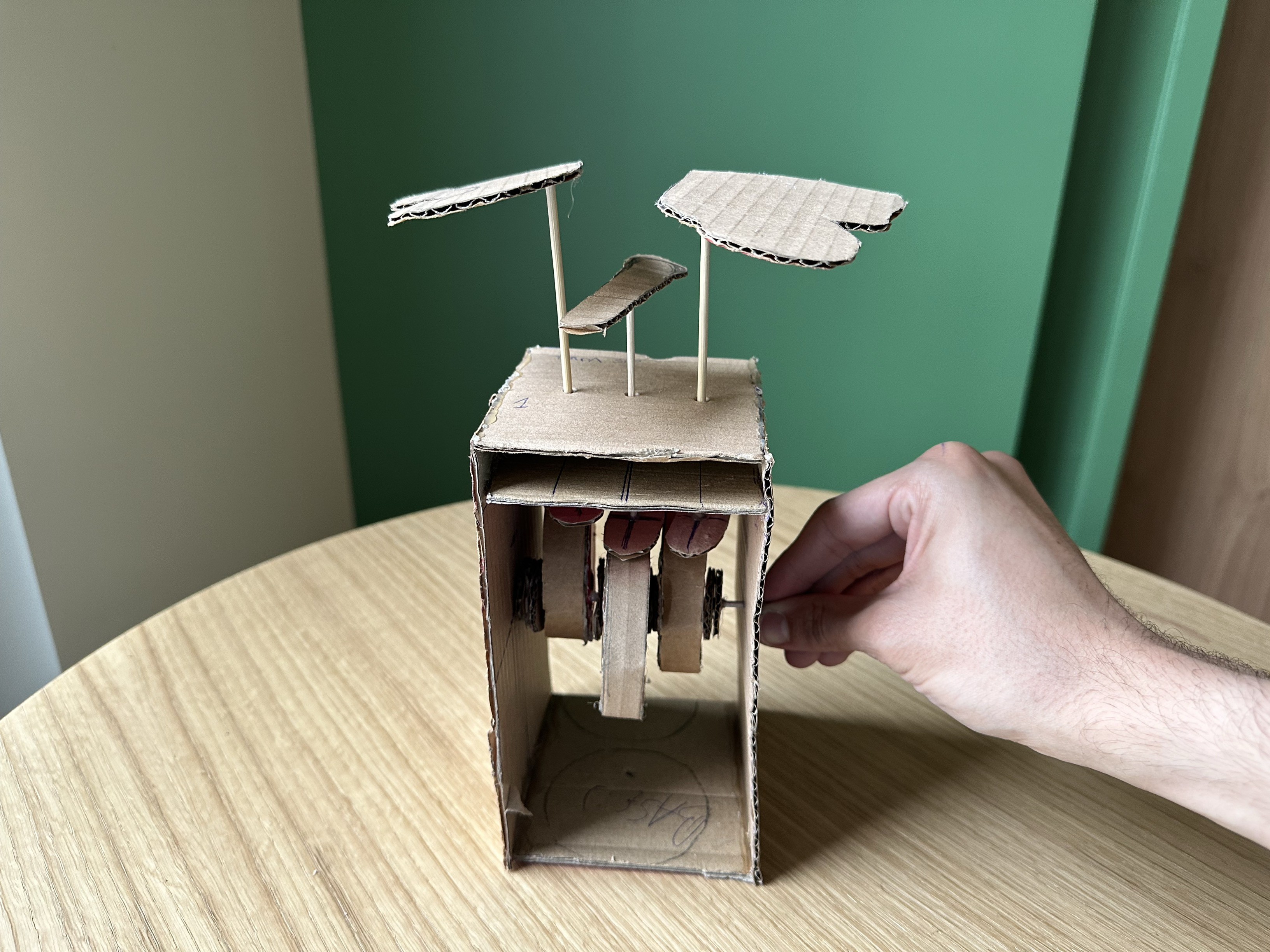
The aim of this project is to create a steam train and demonstrate various mechanical movements using an integrated drive gear system. The primary mechanism involves a drive gear that propels the entire gear system, showcasing the intricacies of mechanical motion. Additionally, we aim to illustrate the cam follower mechanism, for which we will design a round cam to simulate the movement of smoke. This feature will enhance the realism of our train model and provide a comprehensive demonstration of how different mechanical components interact.
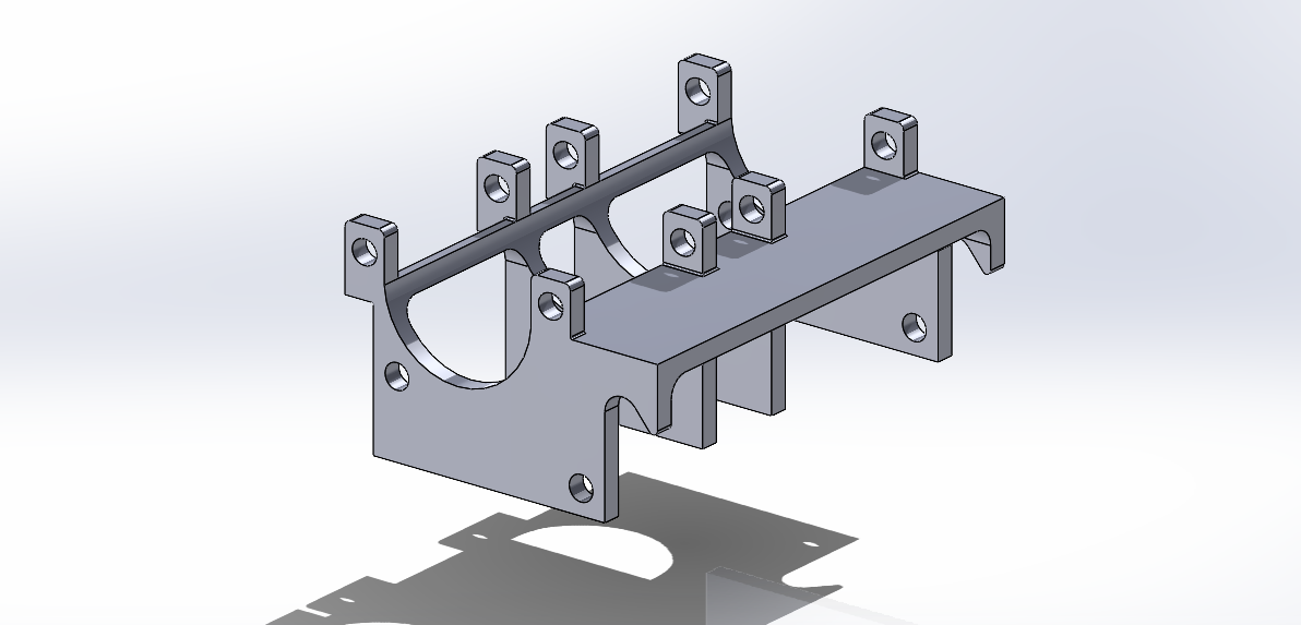
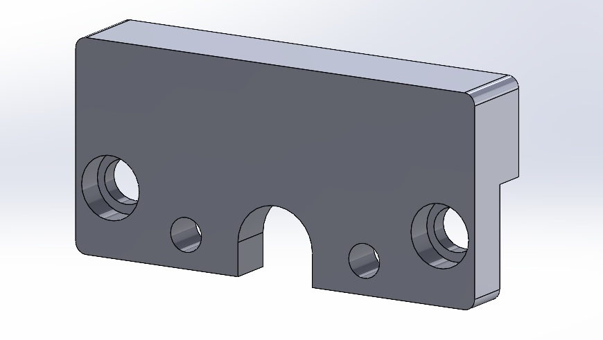
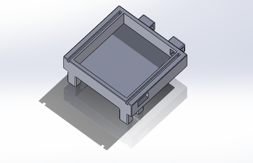
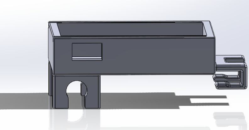
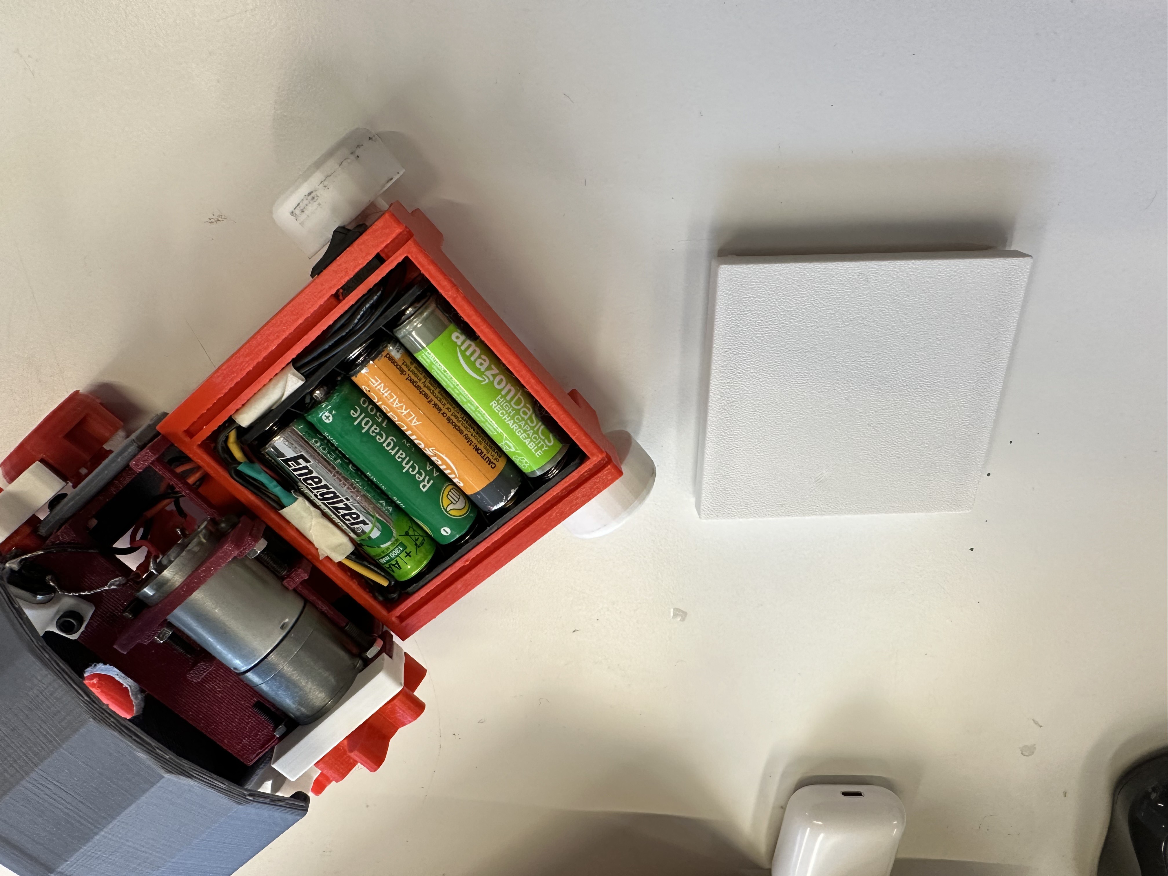
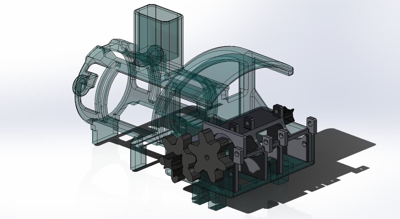
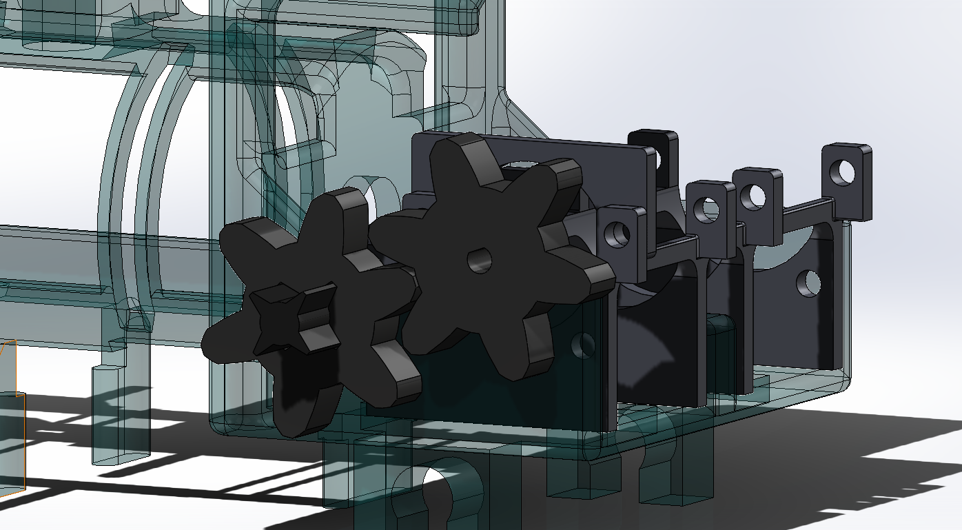
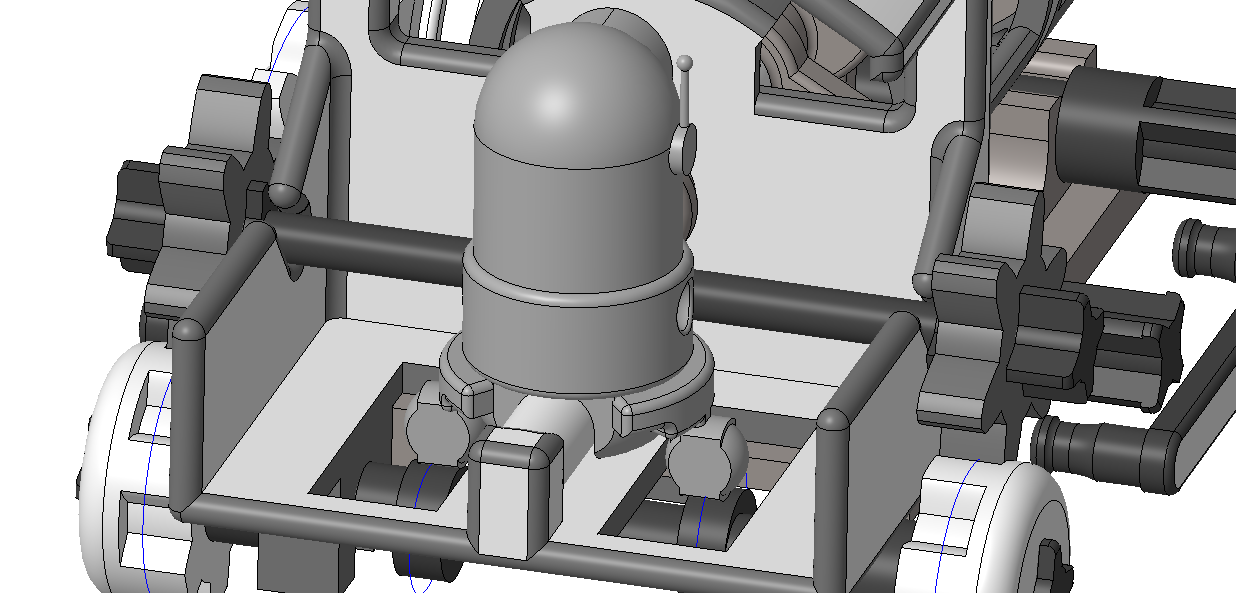
To achieve this, we have meticulously designed and assembled various parts, including the motor mounting support, drive gear, and battery trailer. The motor mounting support includes precise geometries to secure the motor and ensure the drive gear remains in position, preventing any axial displacement. We also designed a trailer to house the batteries, featuring a clip mechanism for optimal attachment to the train body.
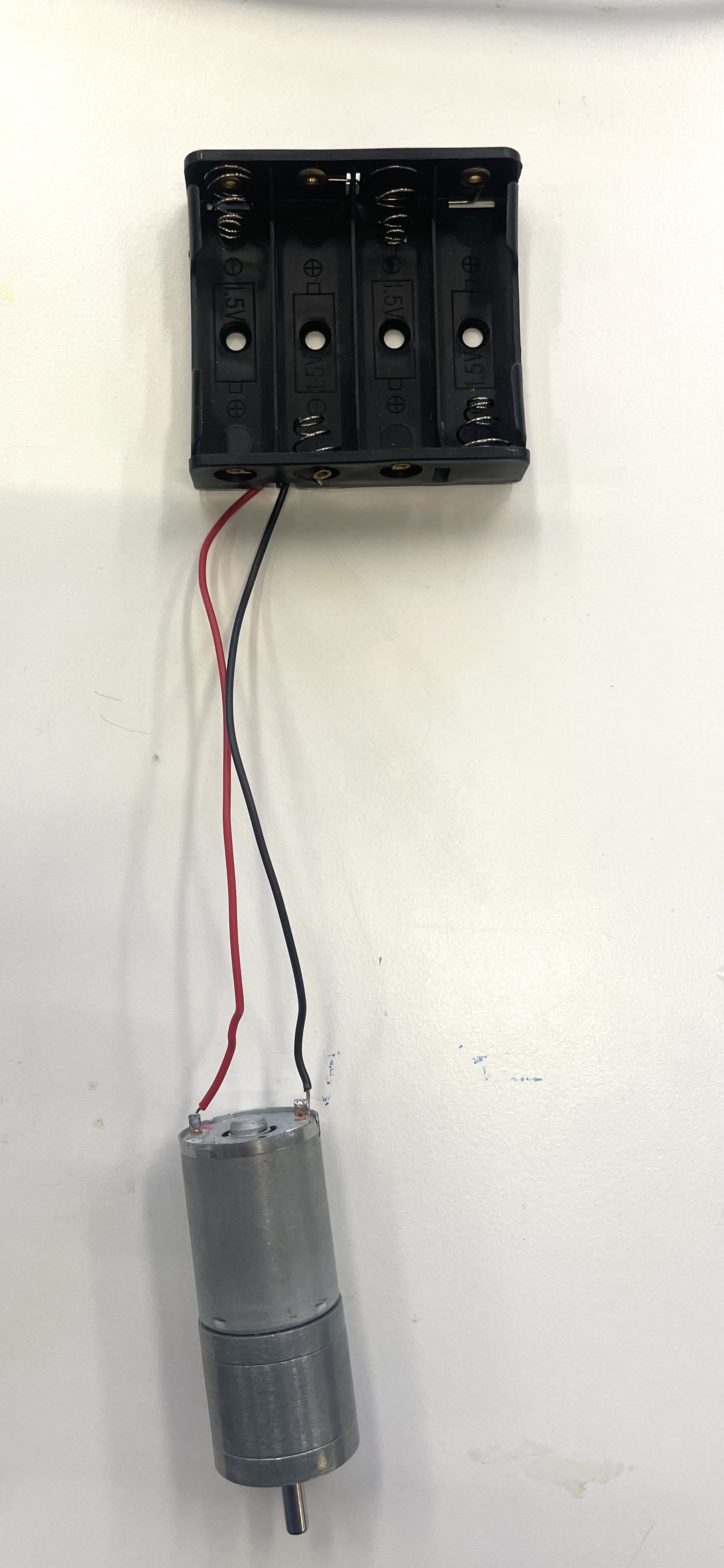
In addressing the challenge of space for multiple batteries, we devised a solution to power both motors with a single battery, carefully soldering the positive and negative wires to ensure a reliable connection. This efficient design not only saves space but also simplifies the electrical setup.
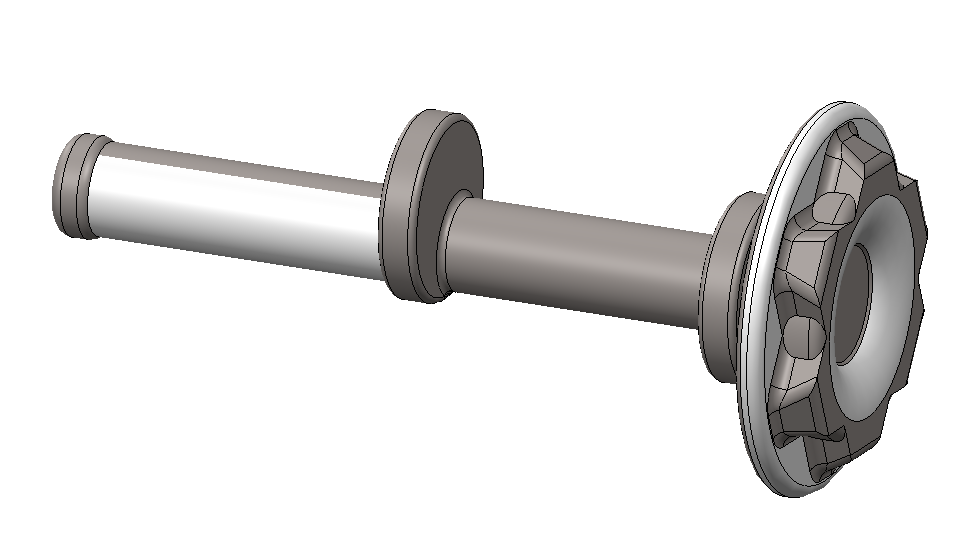
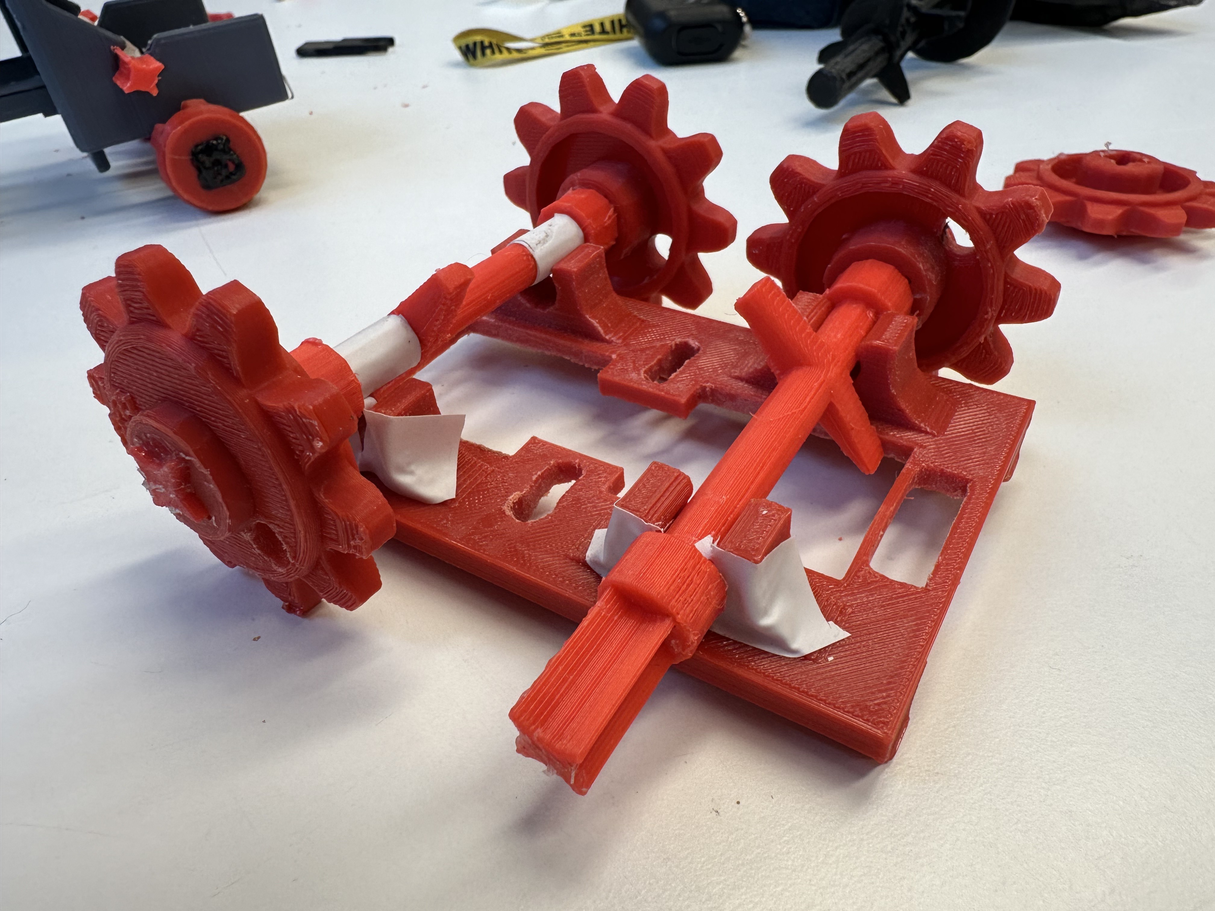
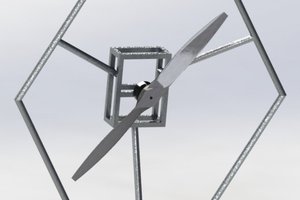
Further enhancements were made to the central axis, where we initially encountered issues with blades causing movement jams. By redesigning the axis and incorporating additional gears, we automated the system to better demonstrate the cam follower mechanism for the smoke effect. The precise placement of gears and the use of a taut rubber band ensure smooth operation without slippage.
Our comprehensive design also includes features like countersunk screw holes to avoid interference with the drive geared wheel, ensuring seamless rotation and preventing motor to get stuck. These detailed considerations and adjustments contribute to the overall functionality and educational value of the project.
Ultimately, our steam train model aims to provide a visually engaging and representation of mechanical systems, illustrating how different components work together to create a cohesive and functional mechanism.

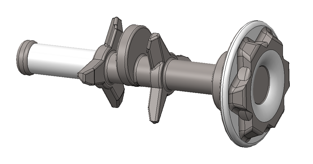
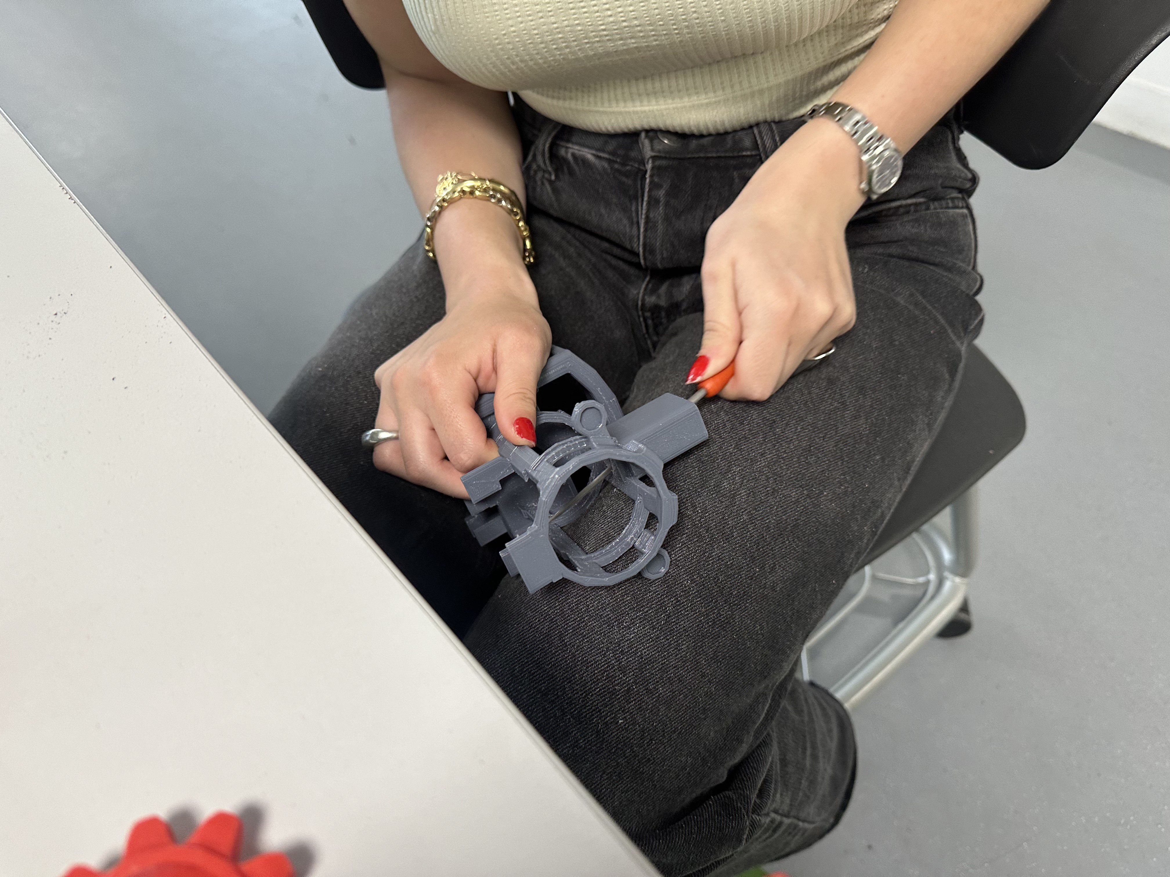
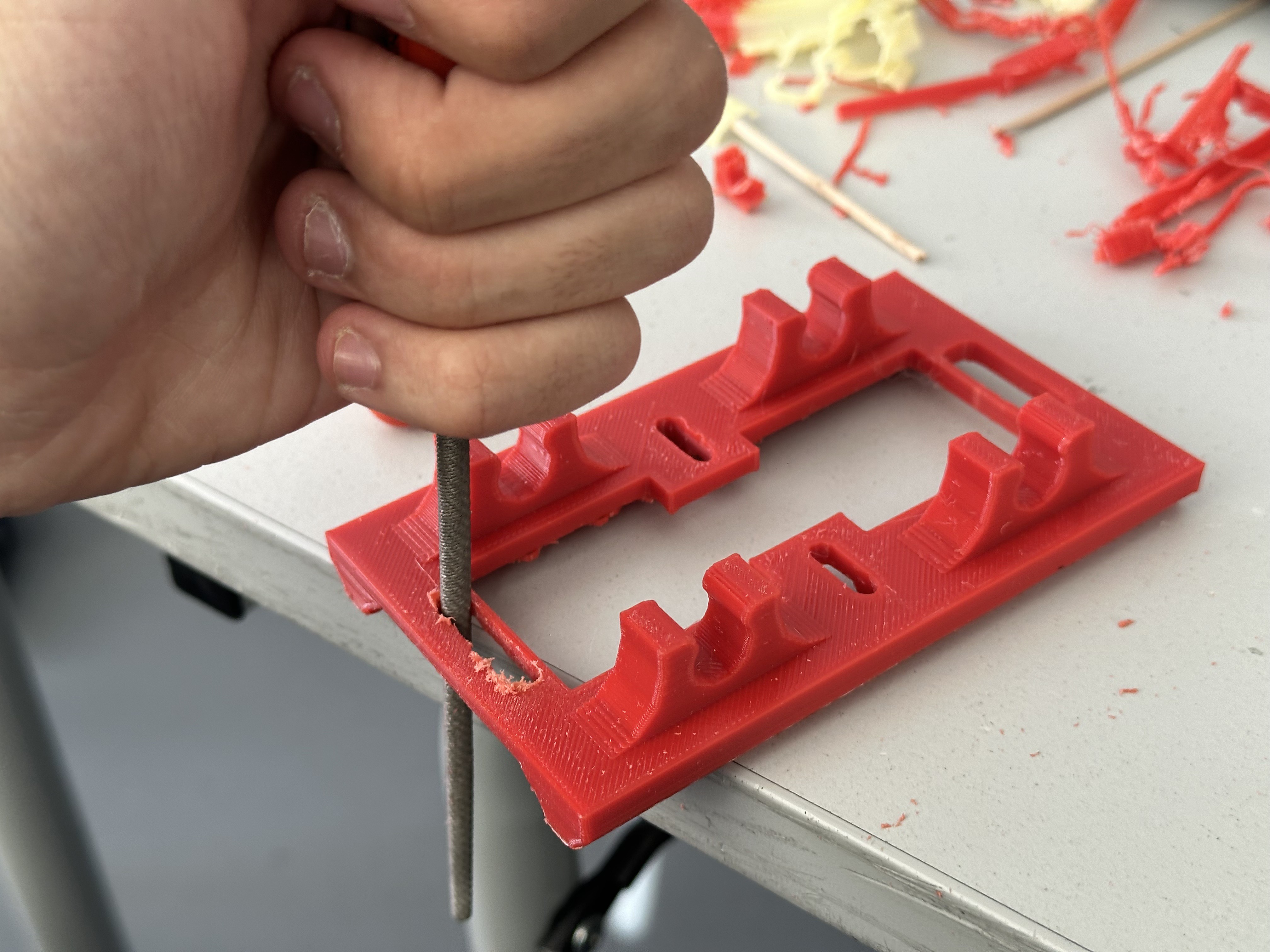
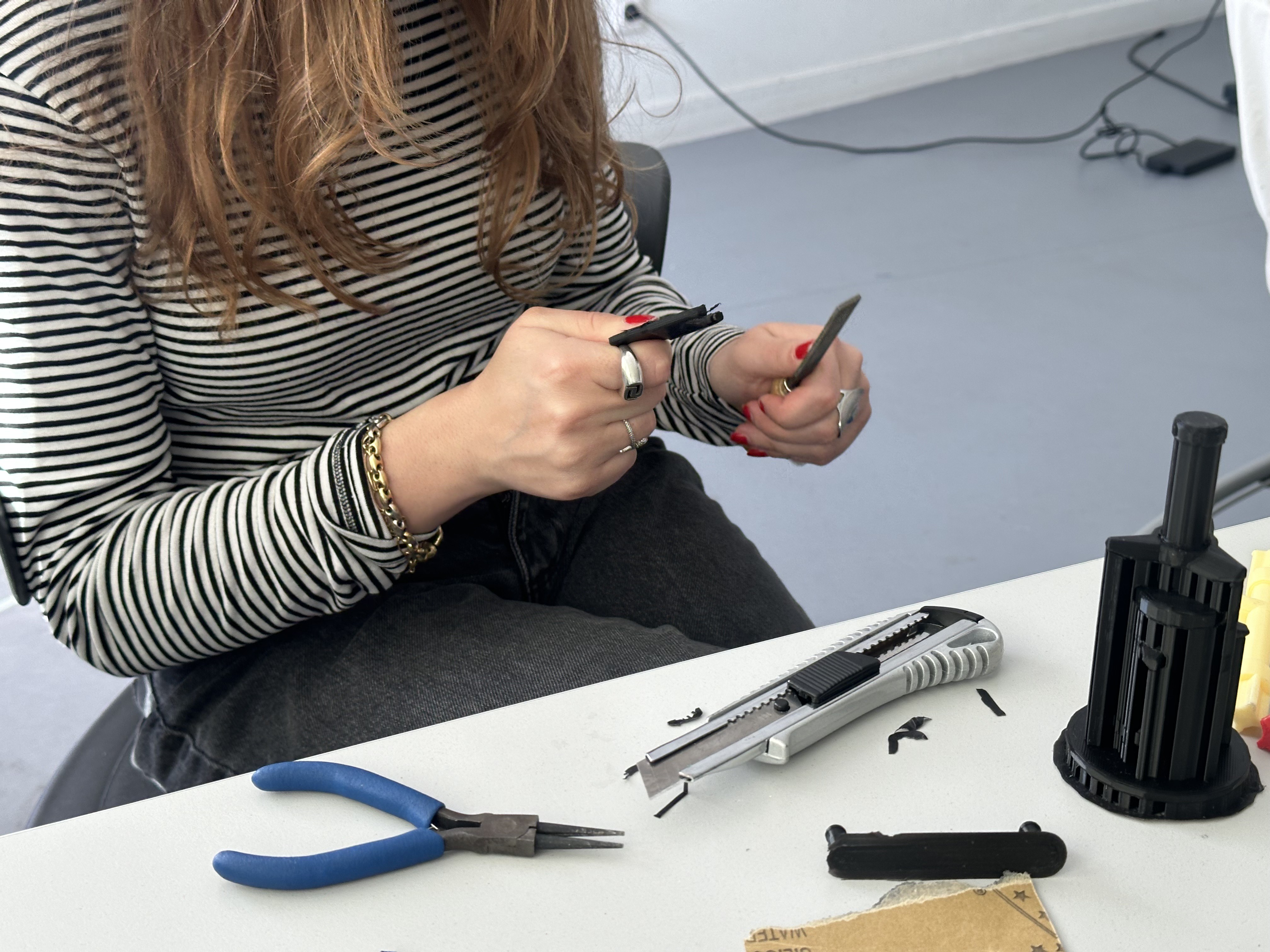
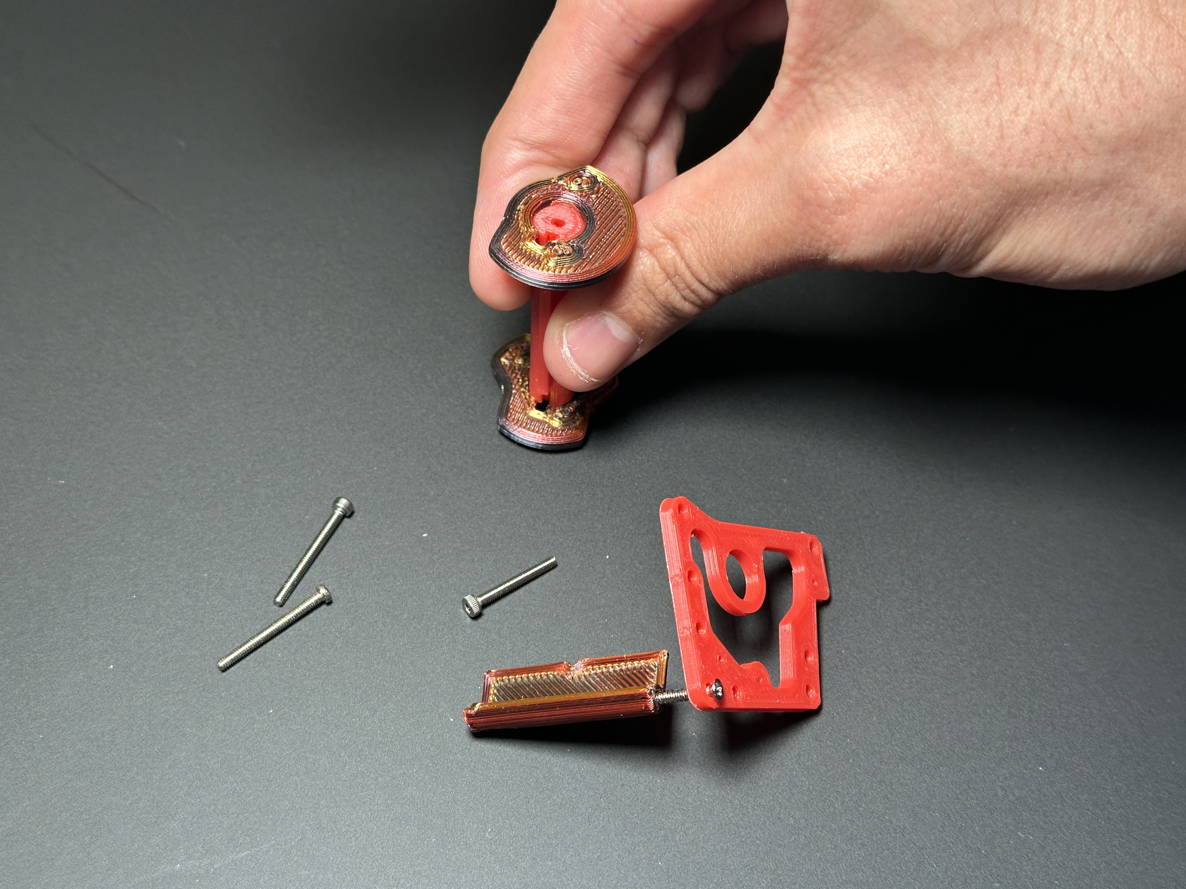
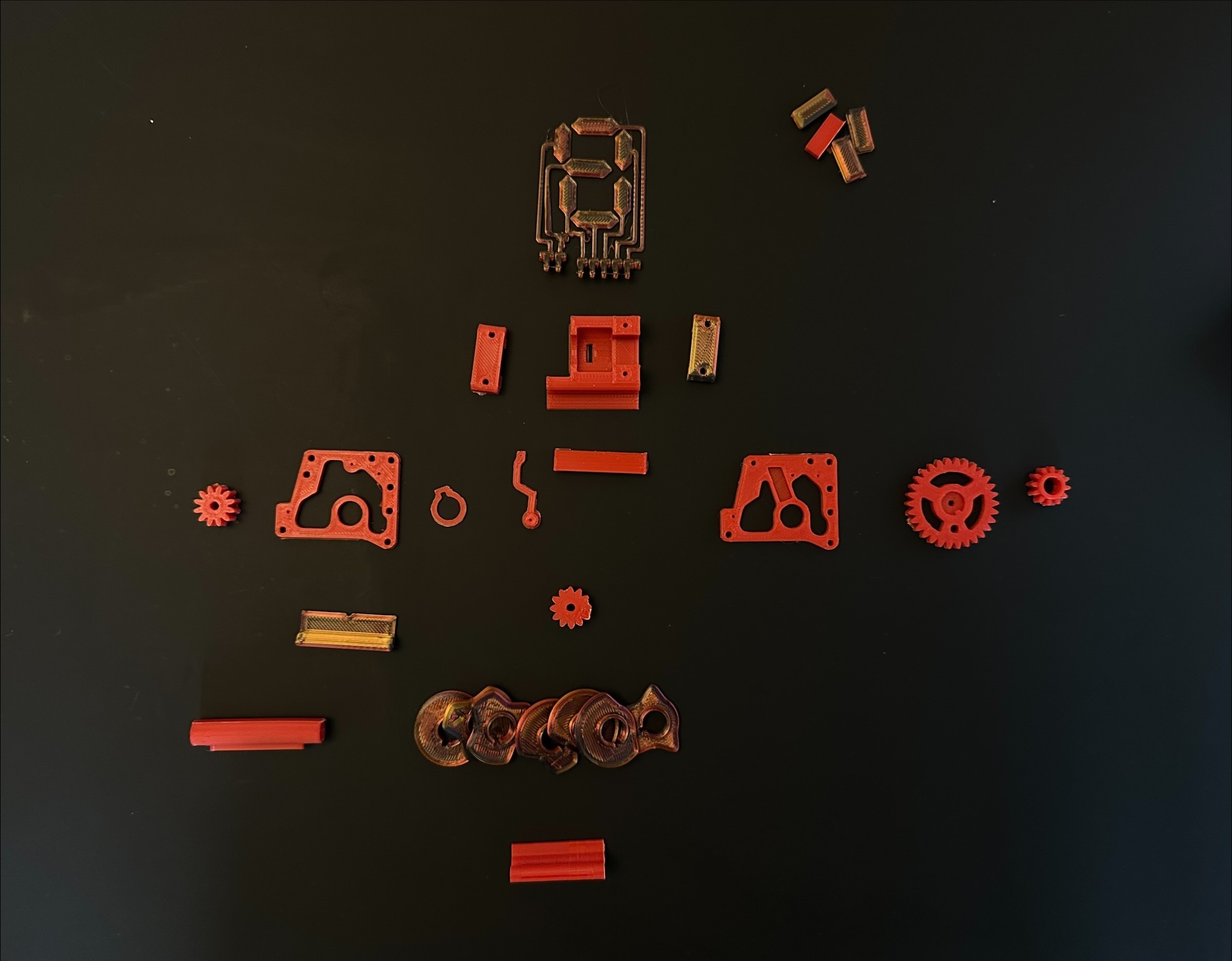
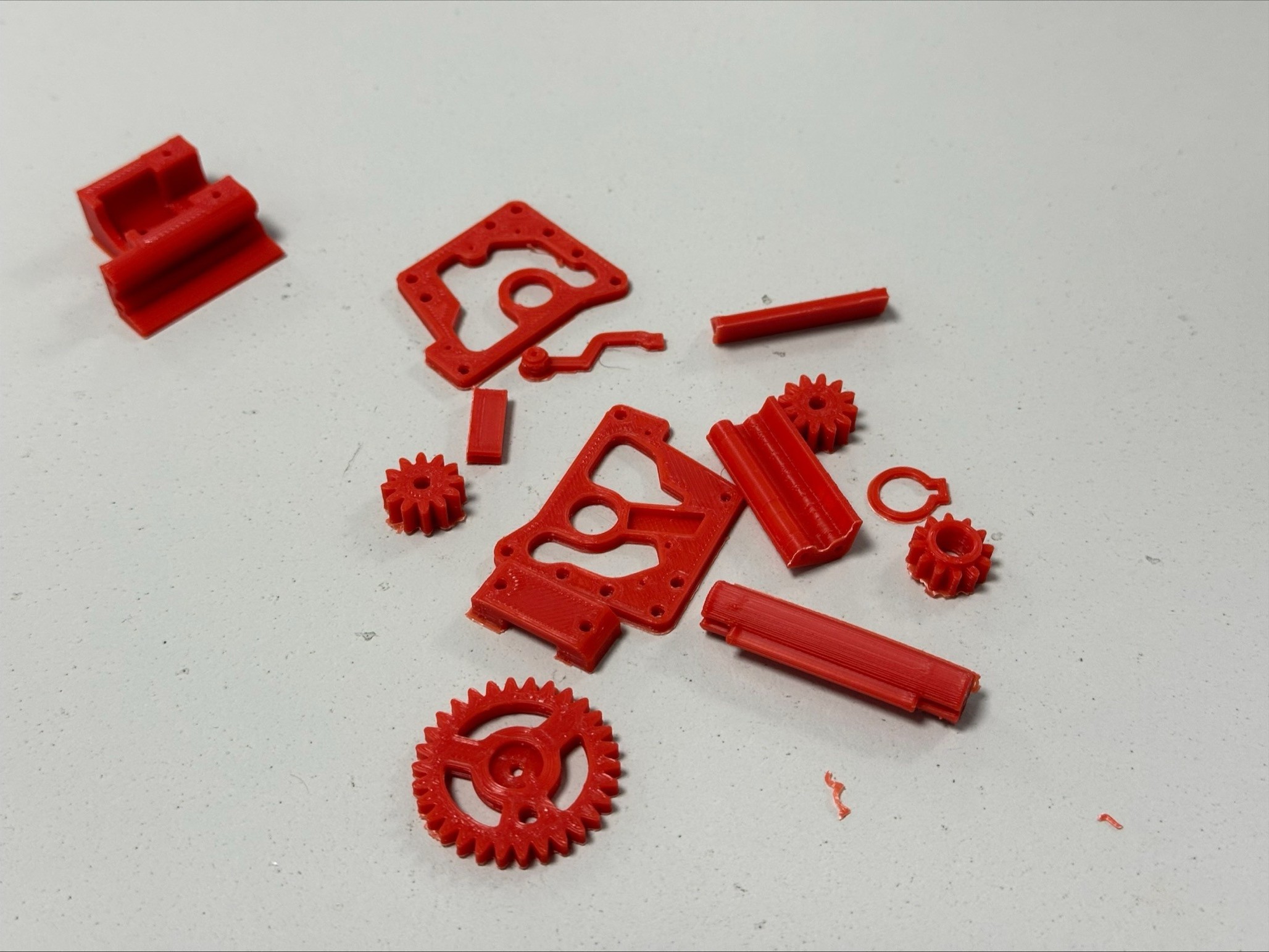
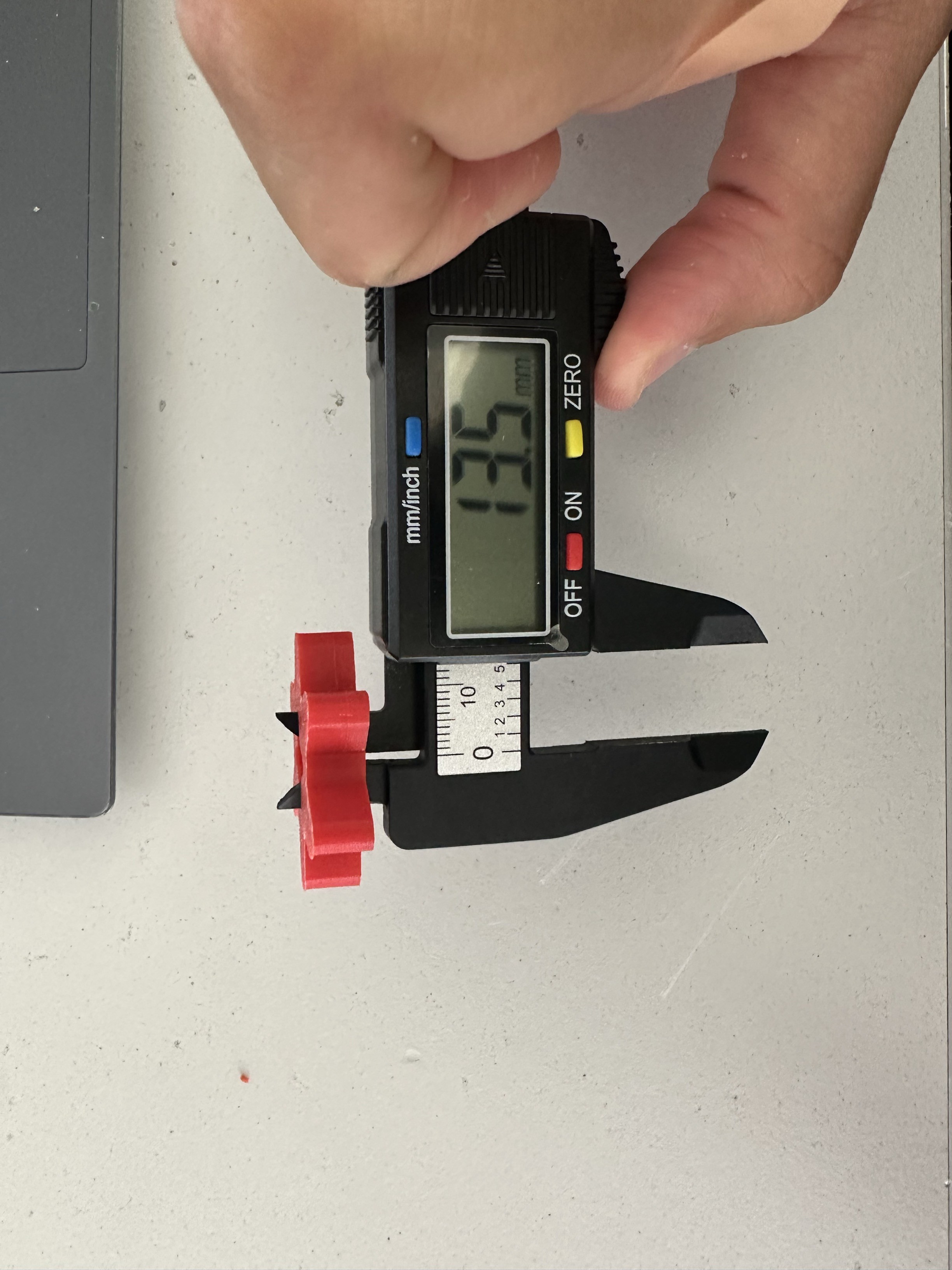 Meticulously measuring the actual pieces for redesigning the parts with the proper tolerances
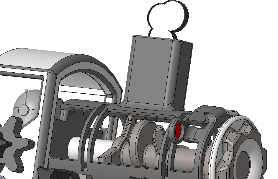
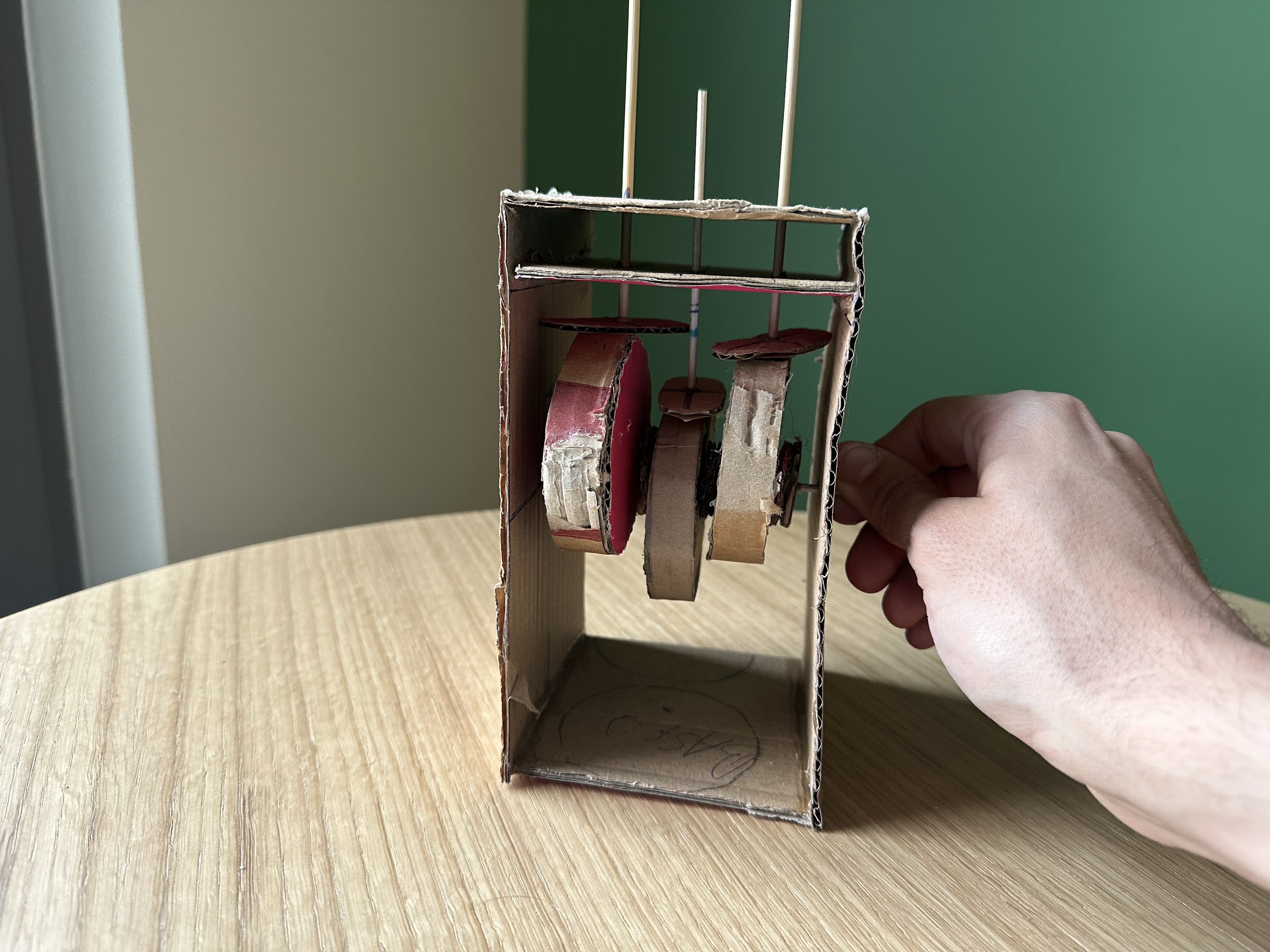
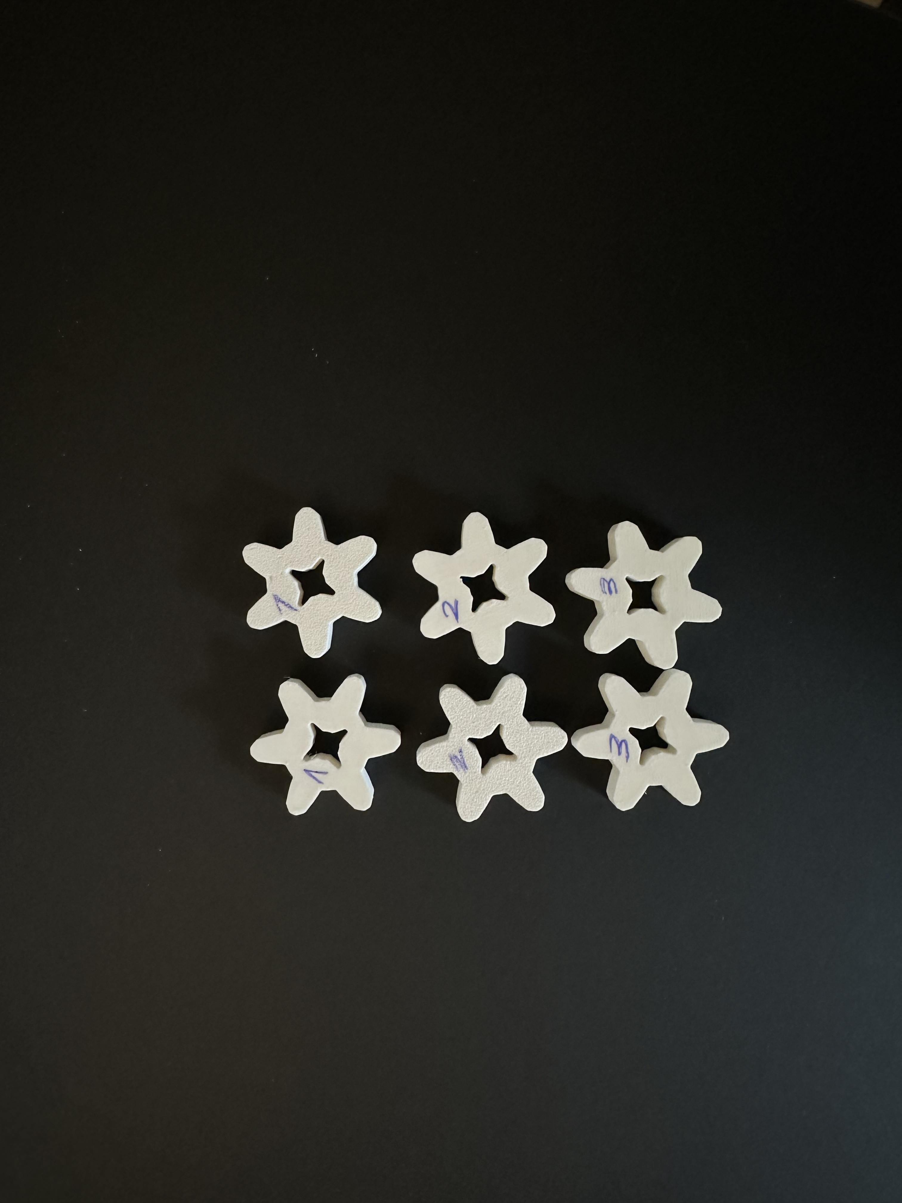
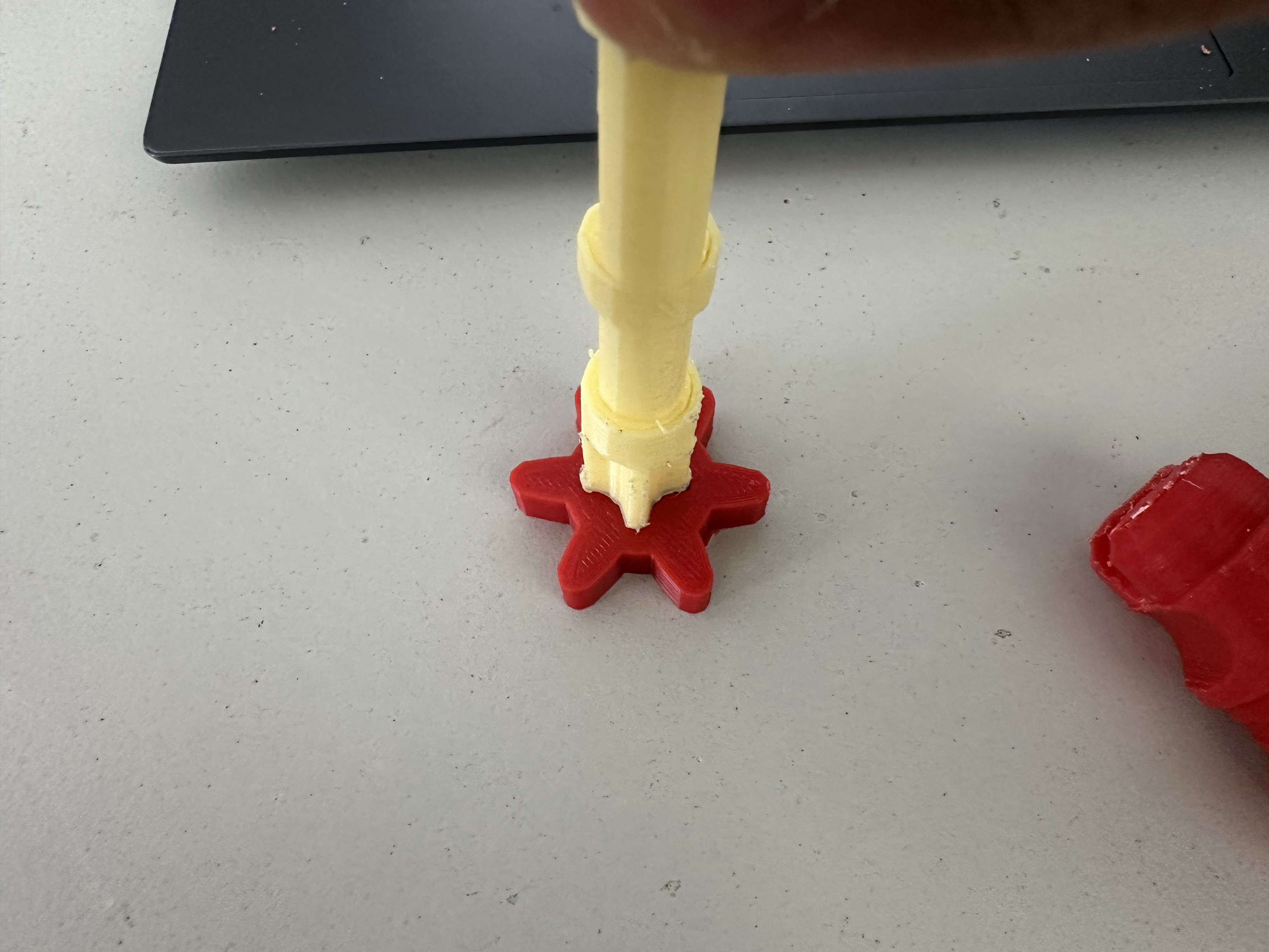
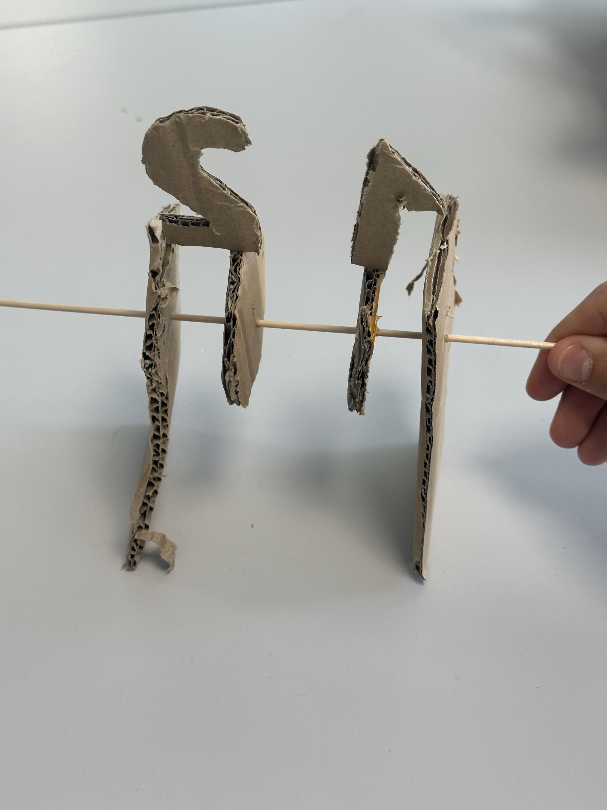
 *Trying out how cams work are working before attaching the animal we want to move.
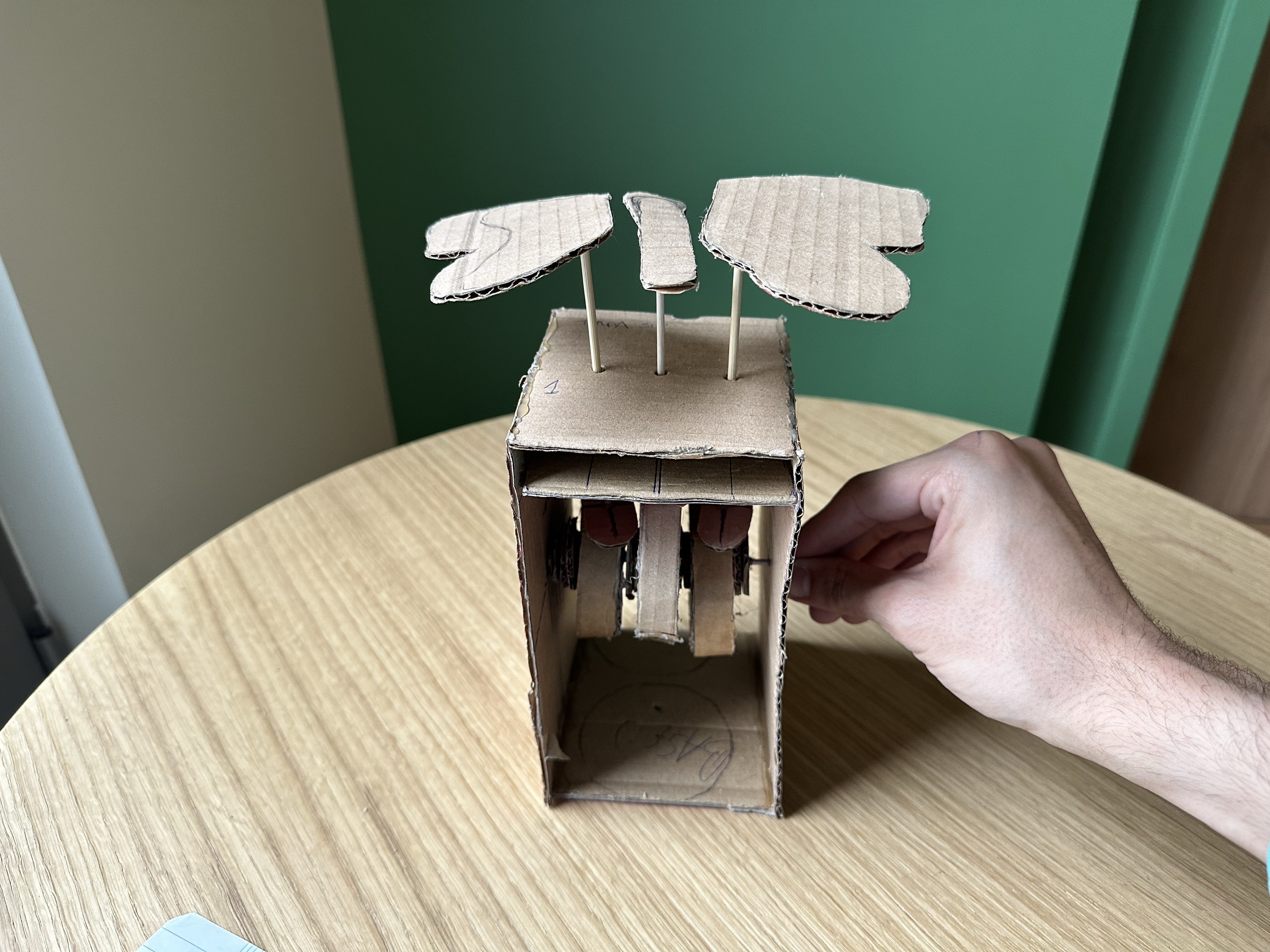
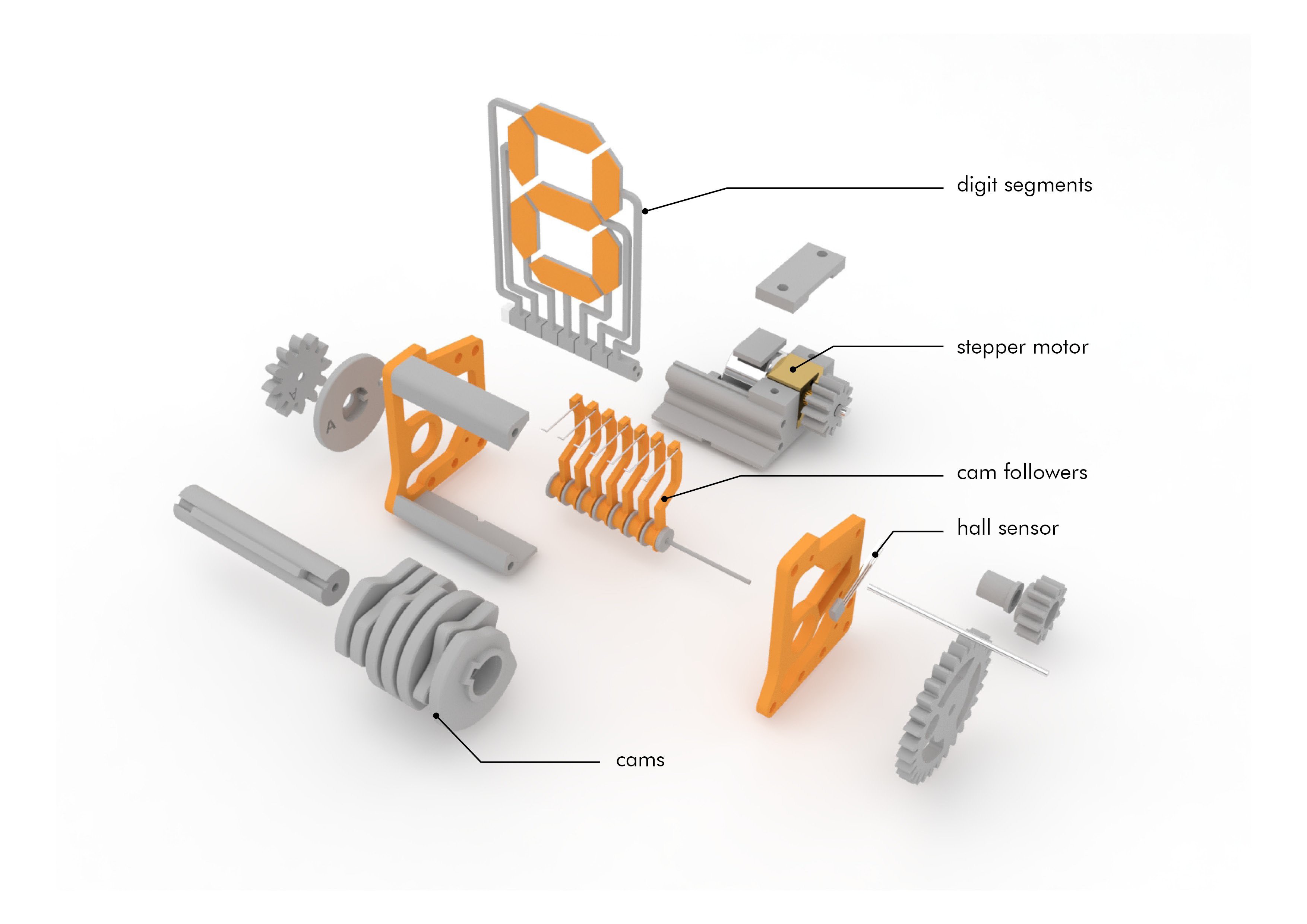
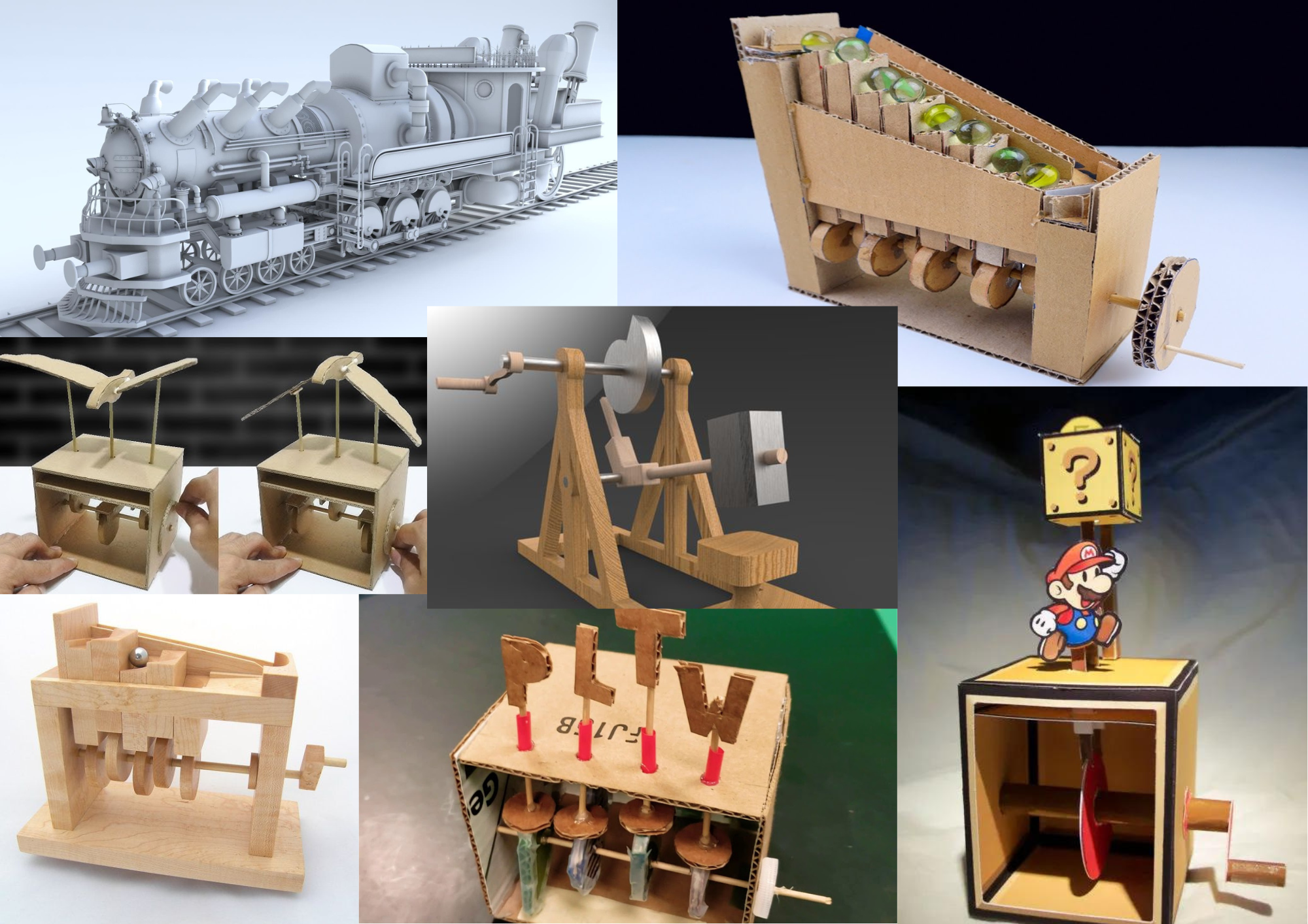
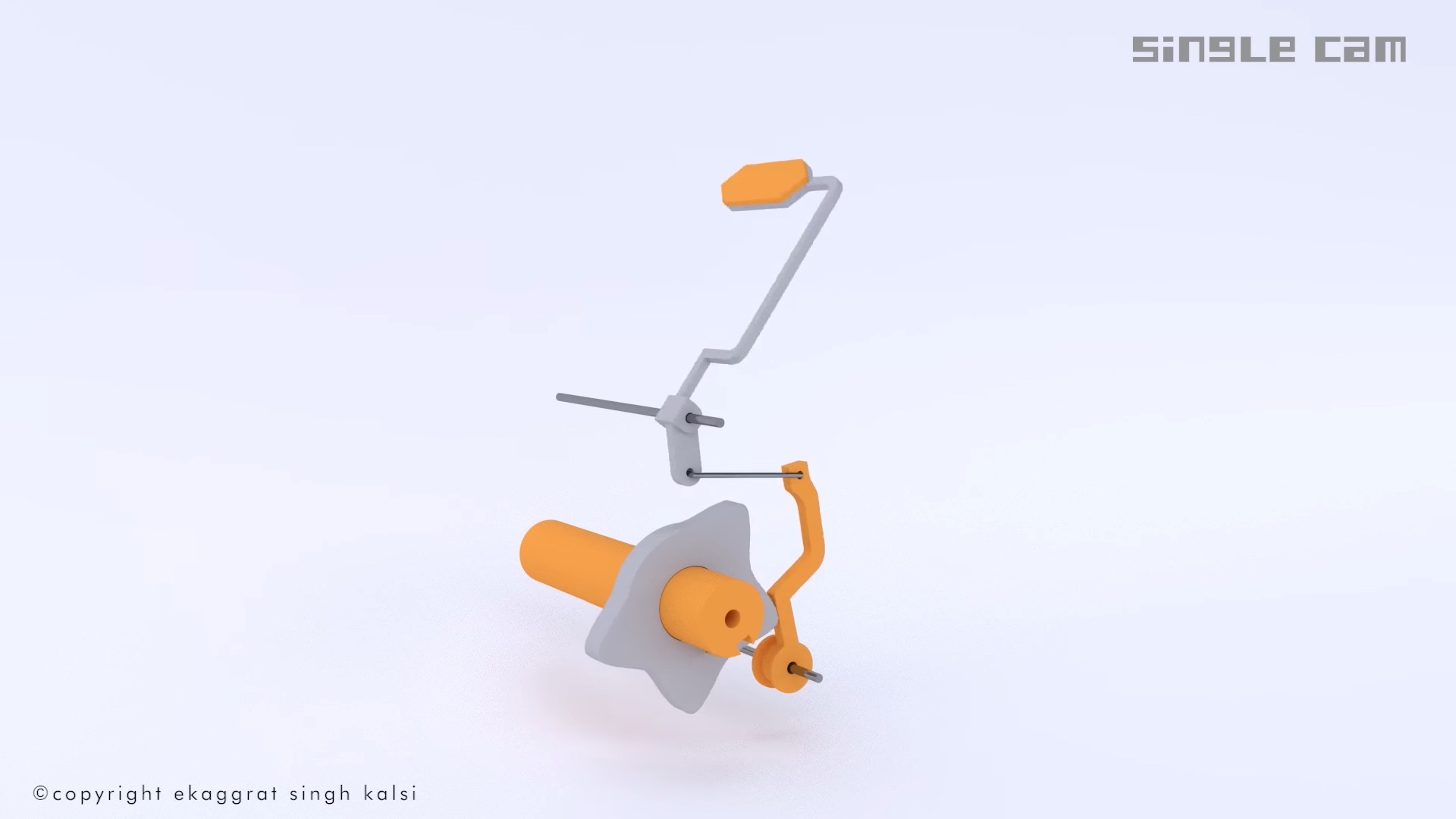
 Explanatory drawing
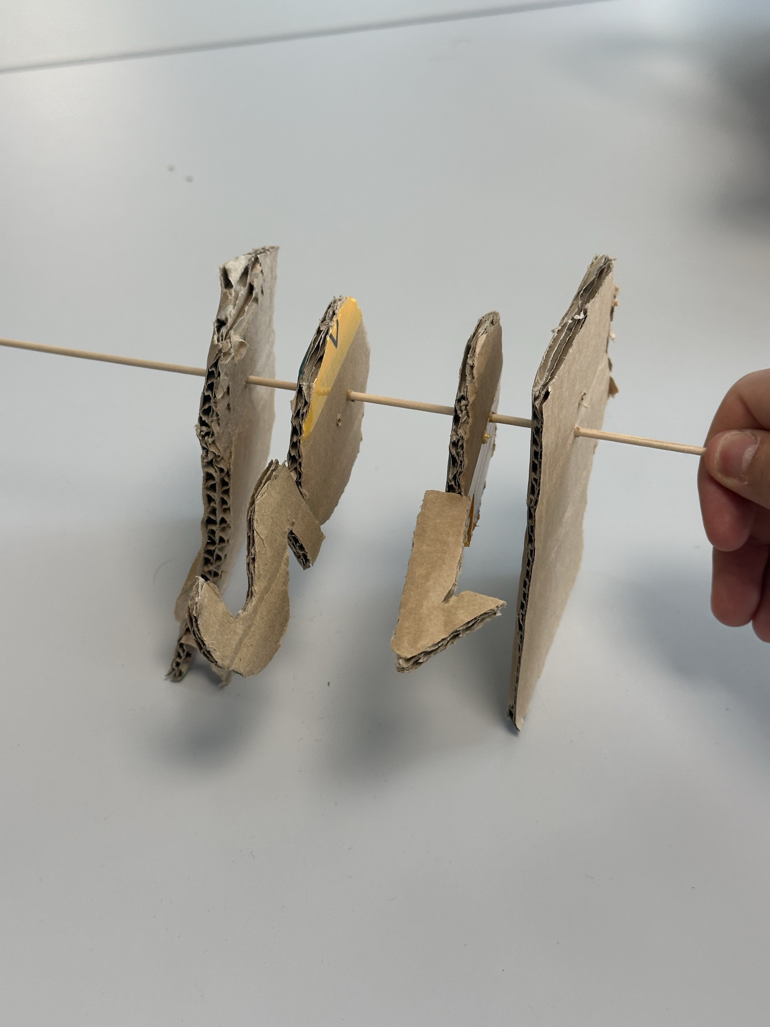


 Peter Buckley
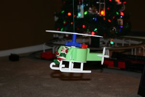
 Mike Rigsby
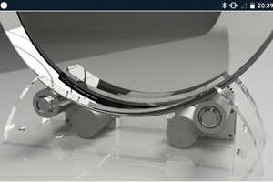
 terryspitz
 ken.do
Question: Is there one or two motors? It looks like one motor drives the wheels and another drives the smoke stack and rotating front. Please advise.