0%
0%
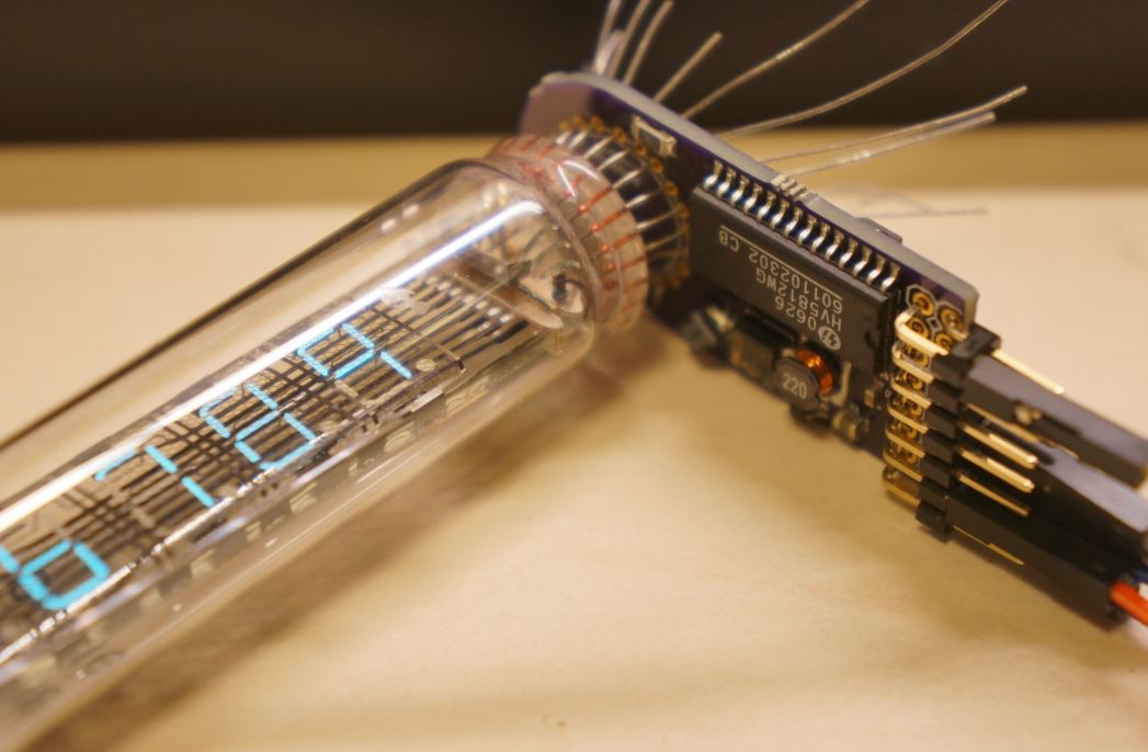
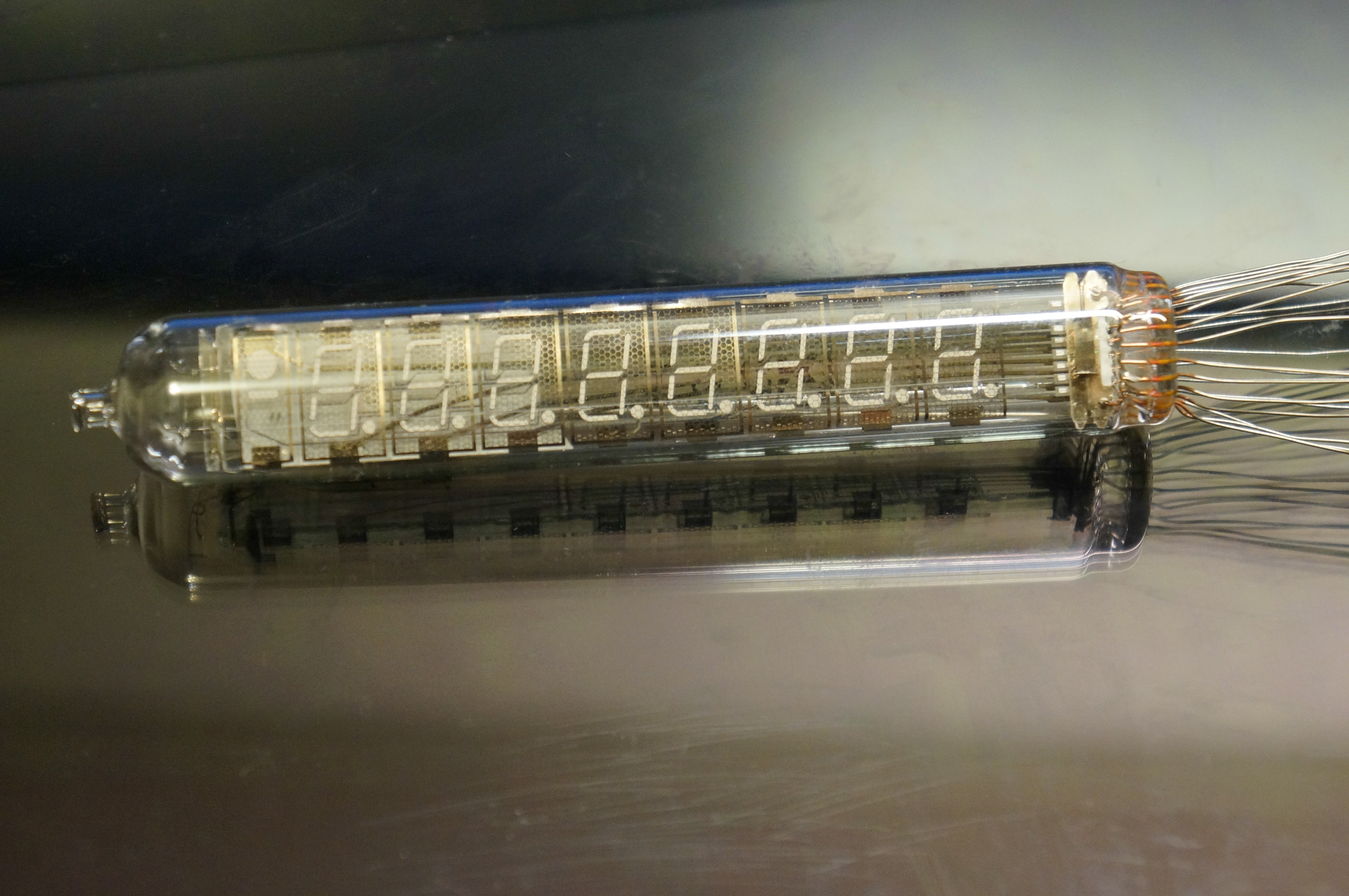
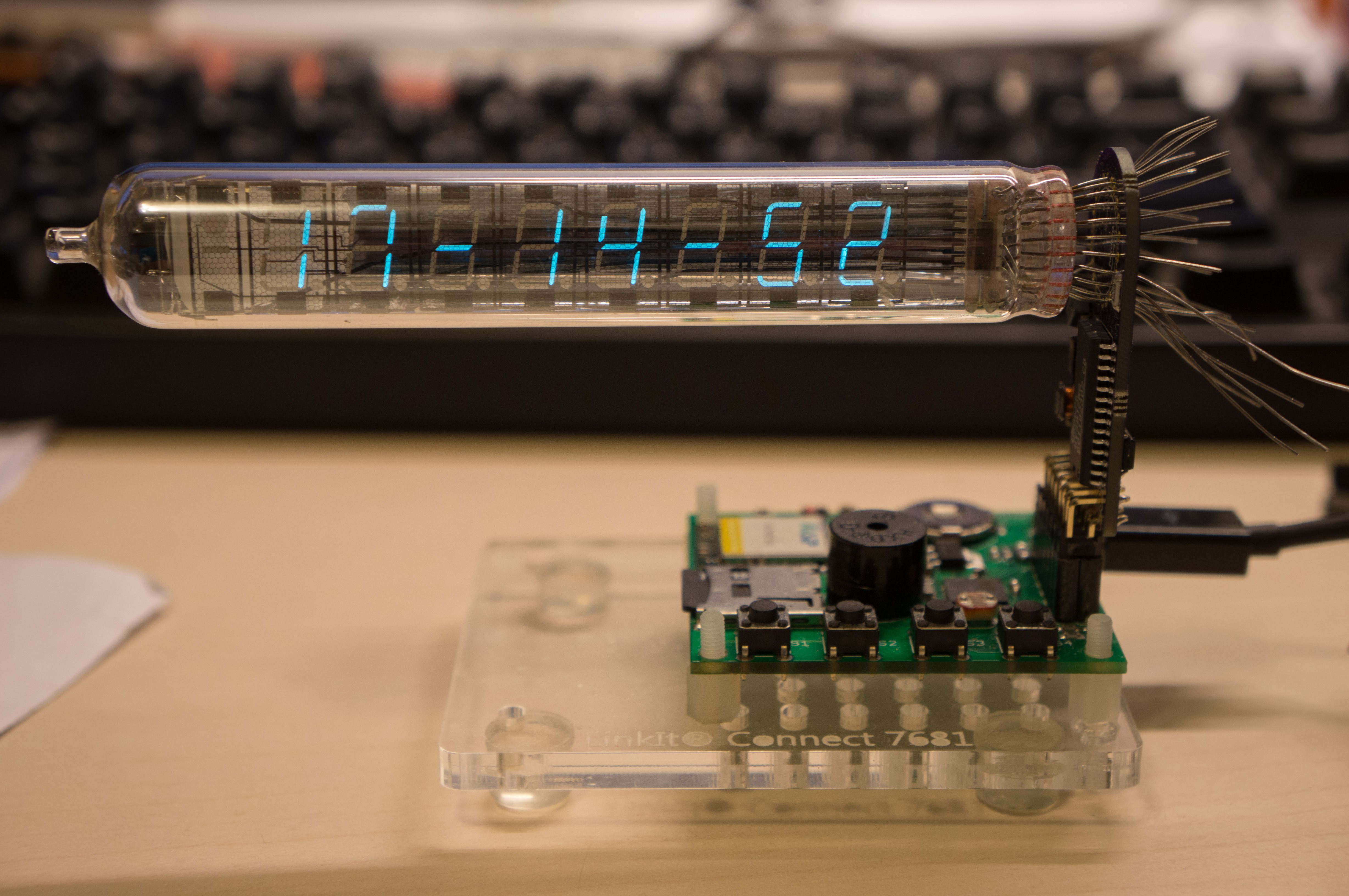
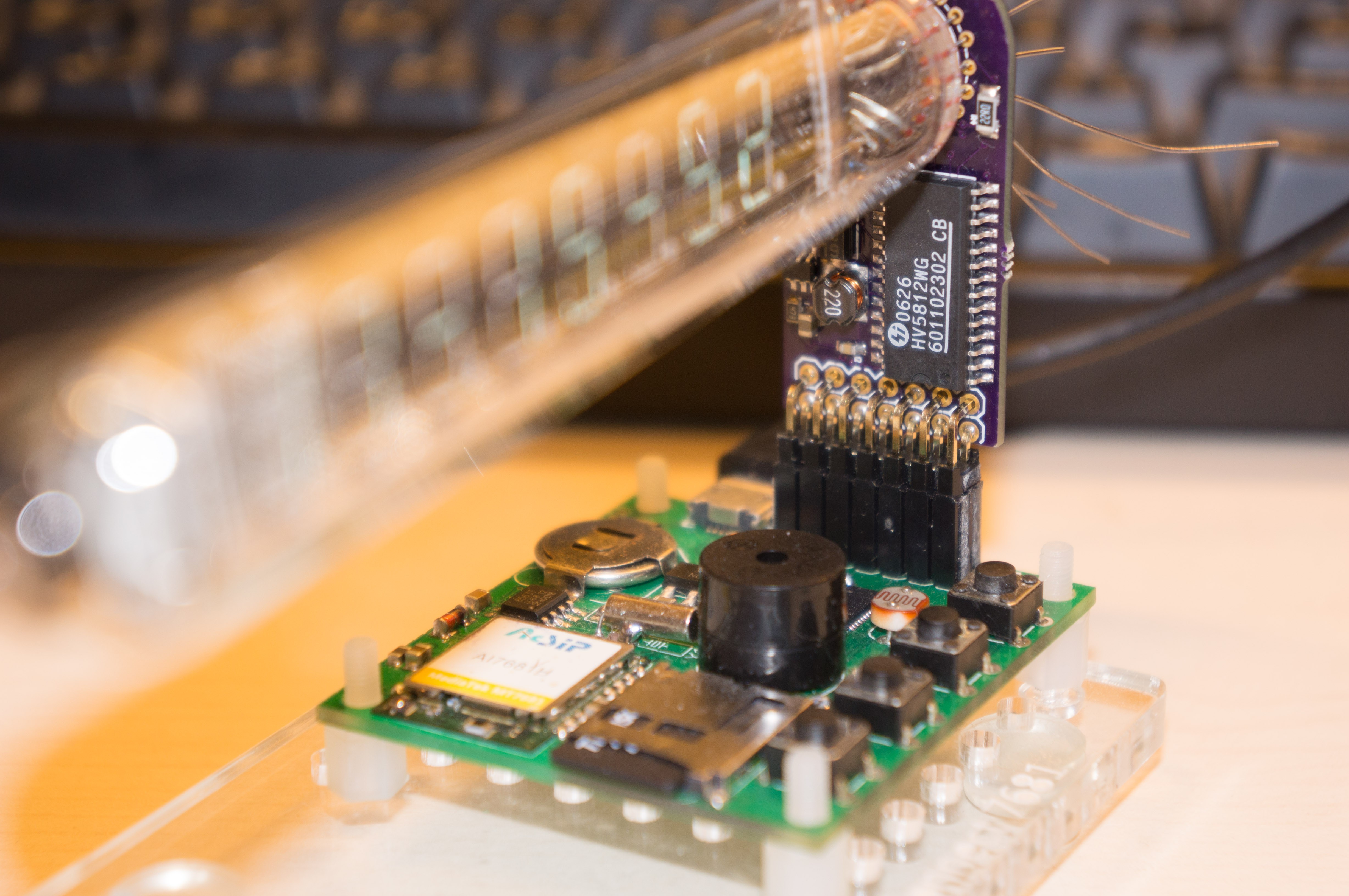
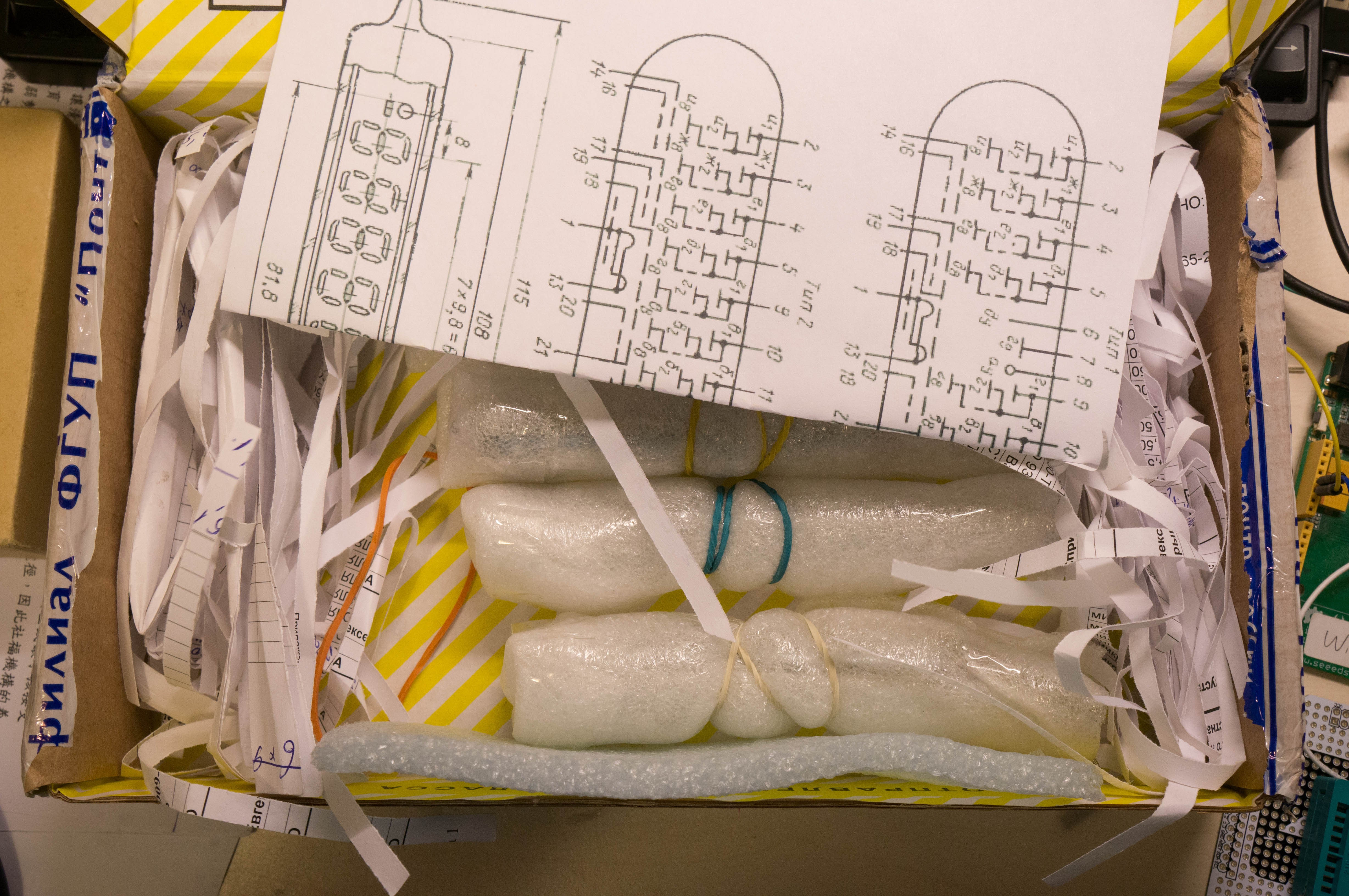
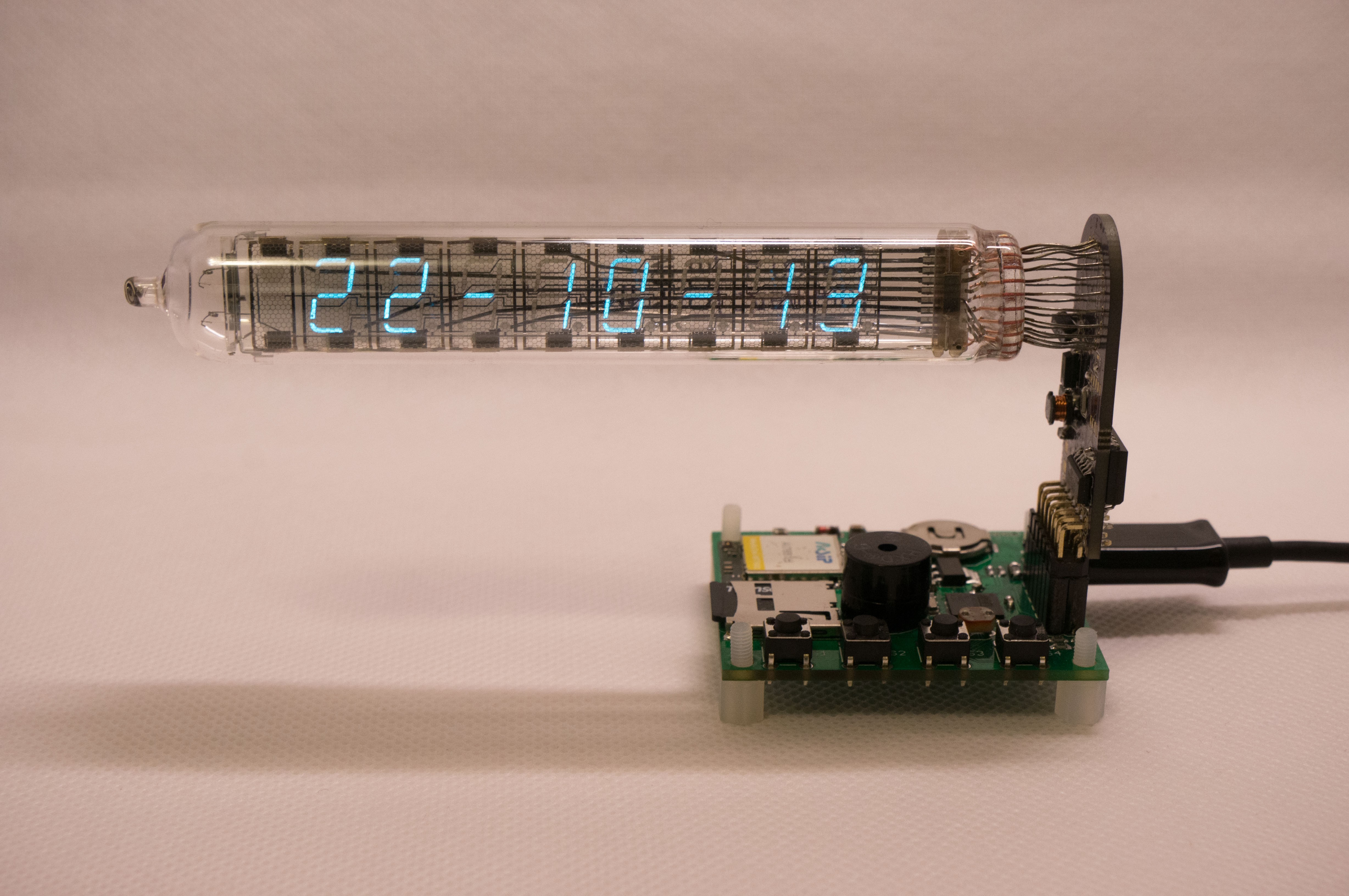
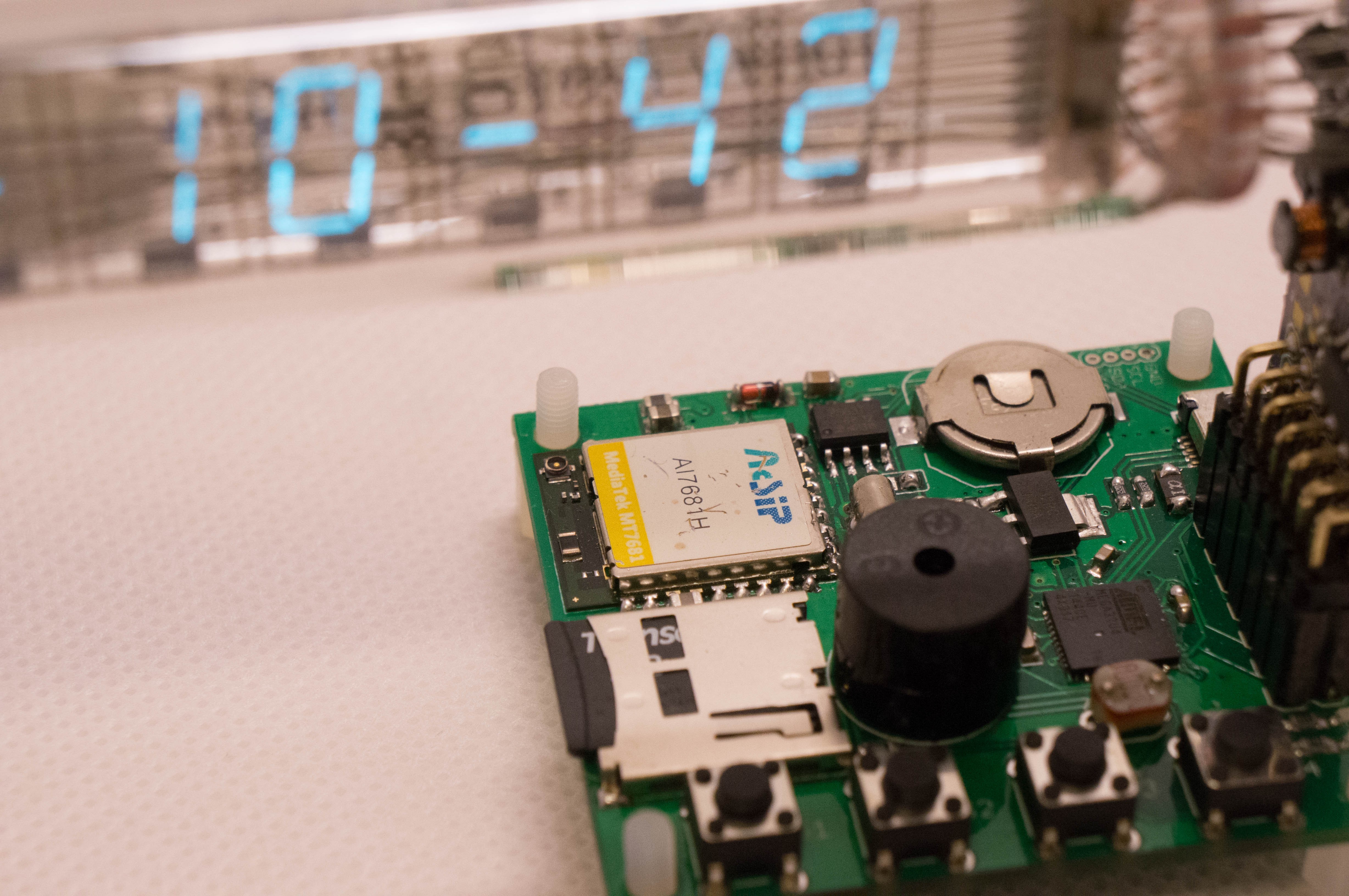
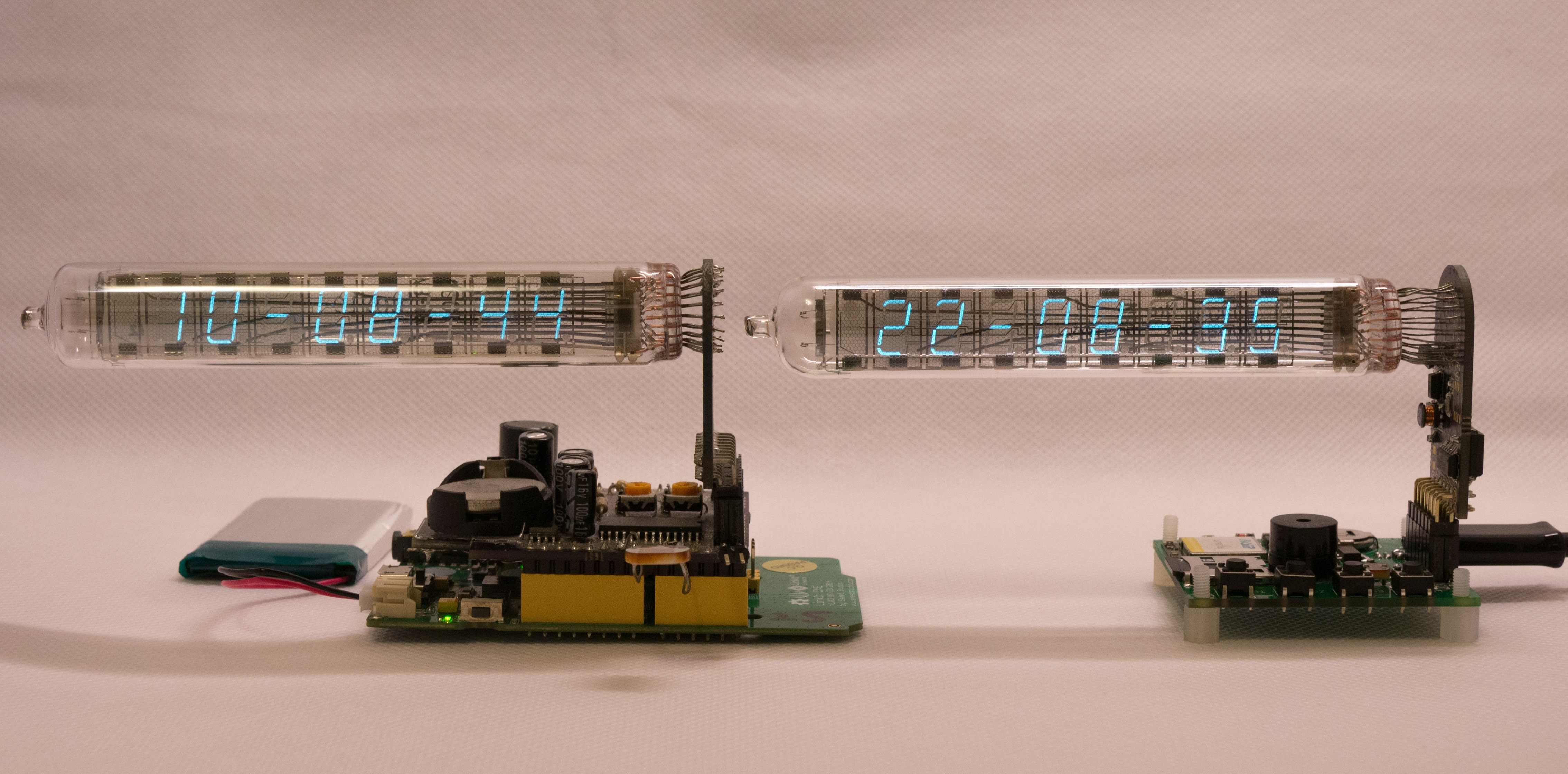
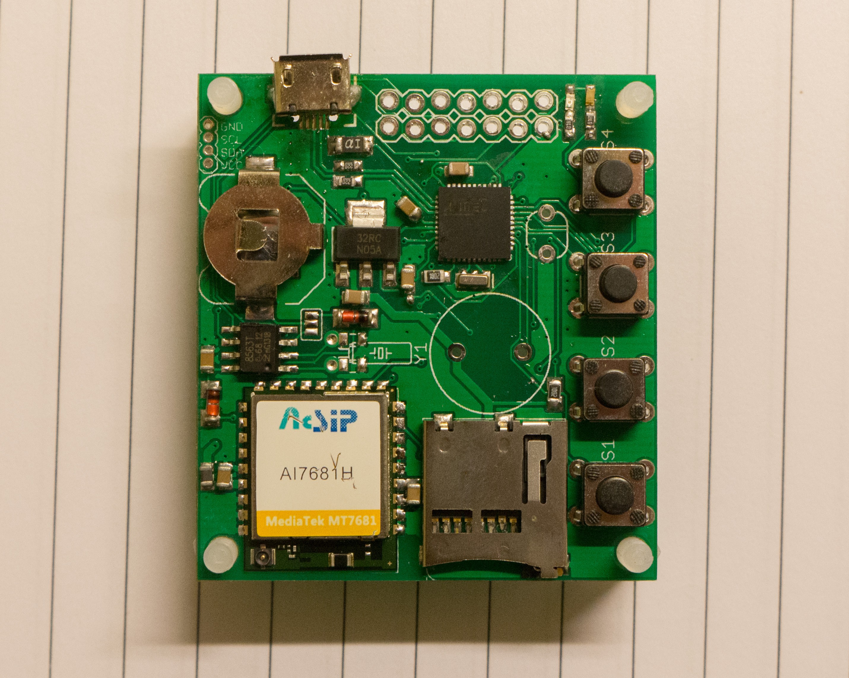
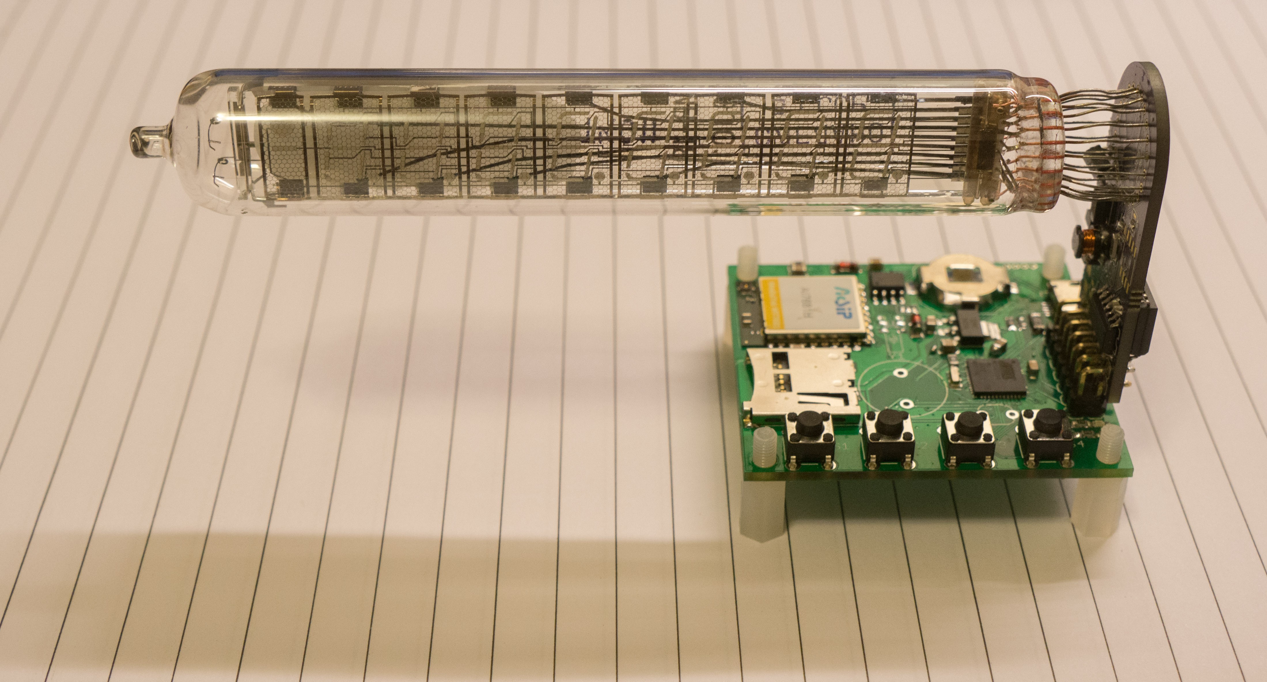
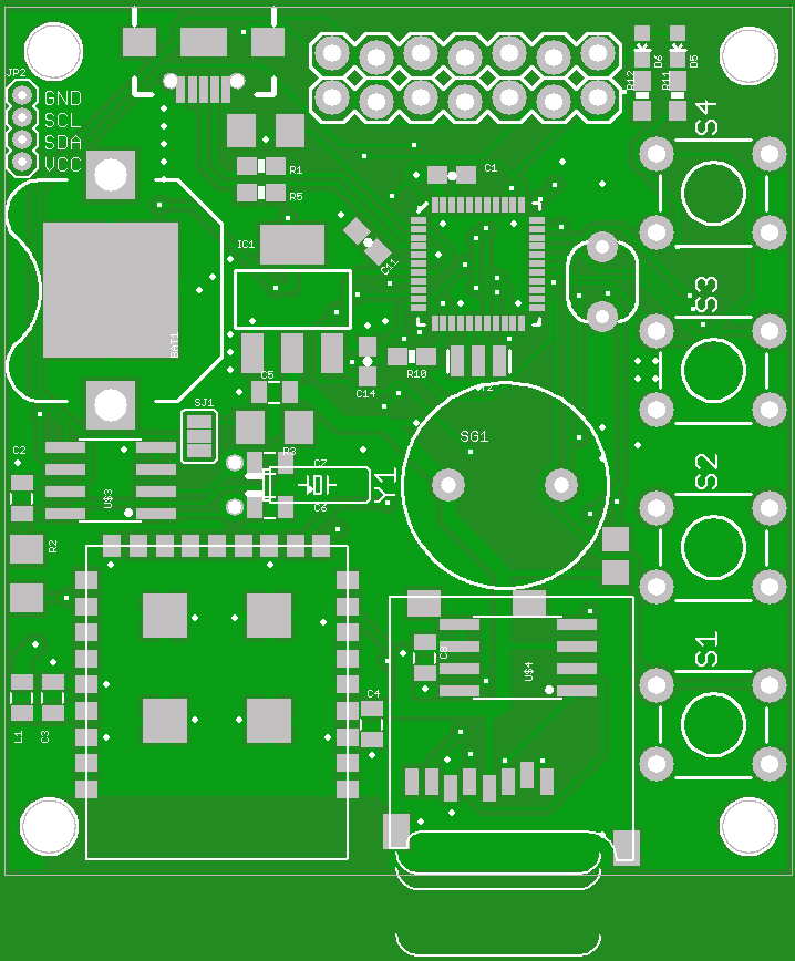
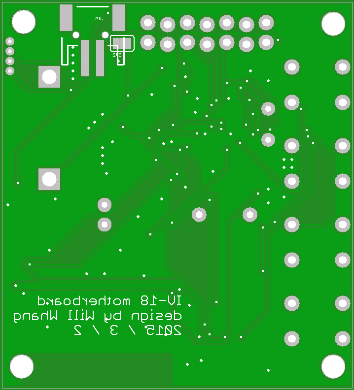
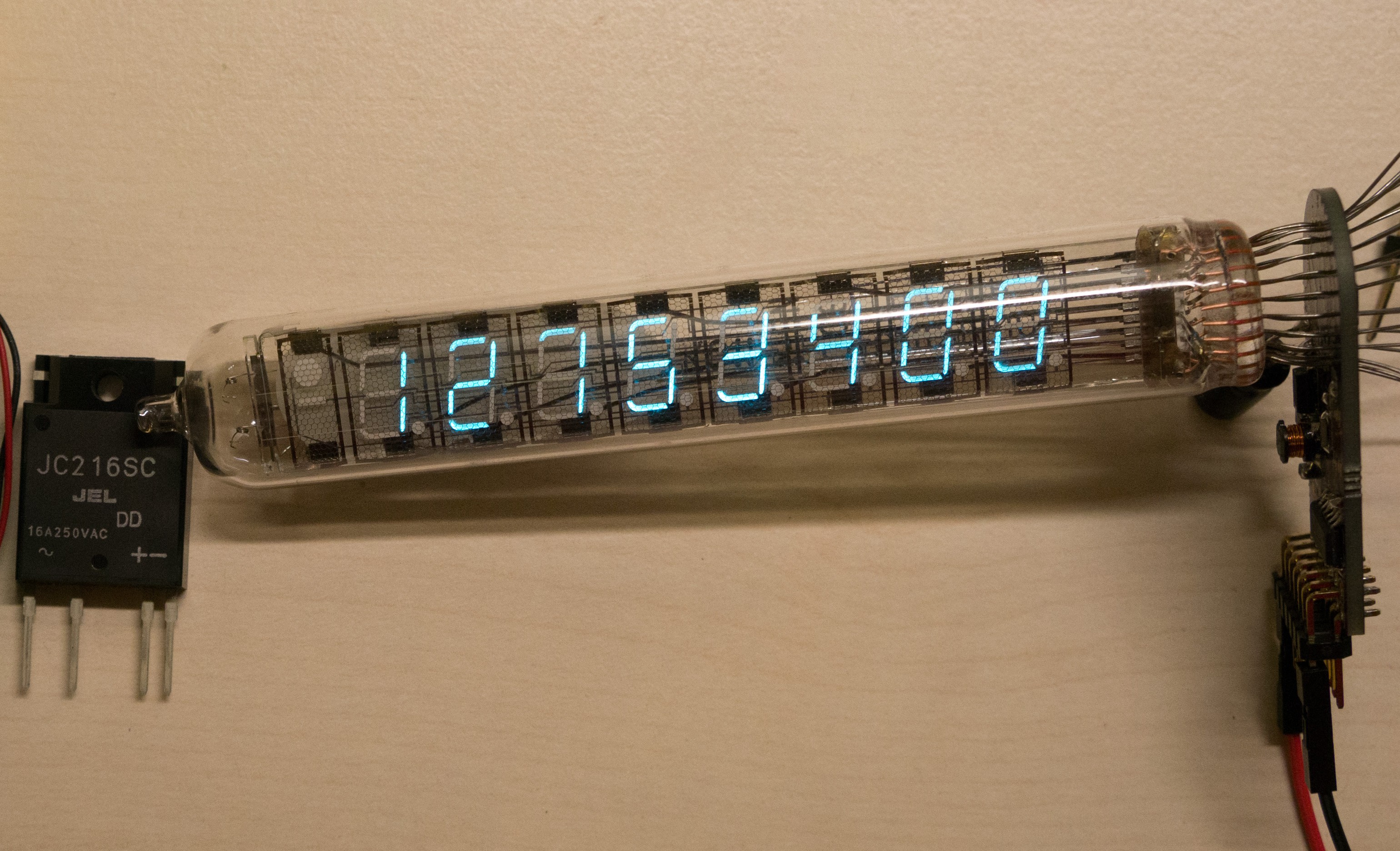
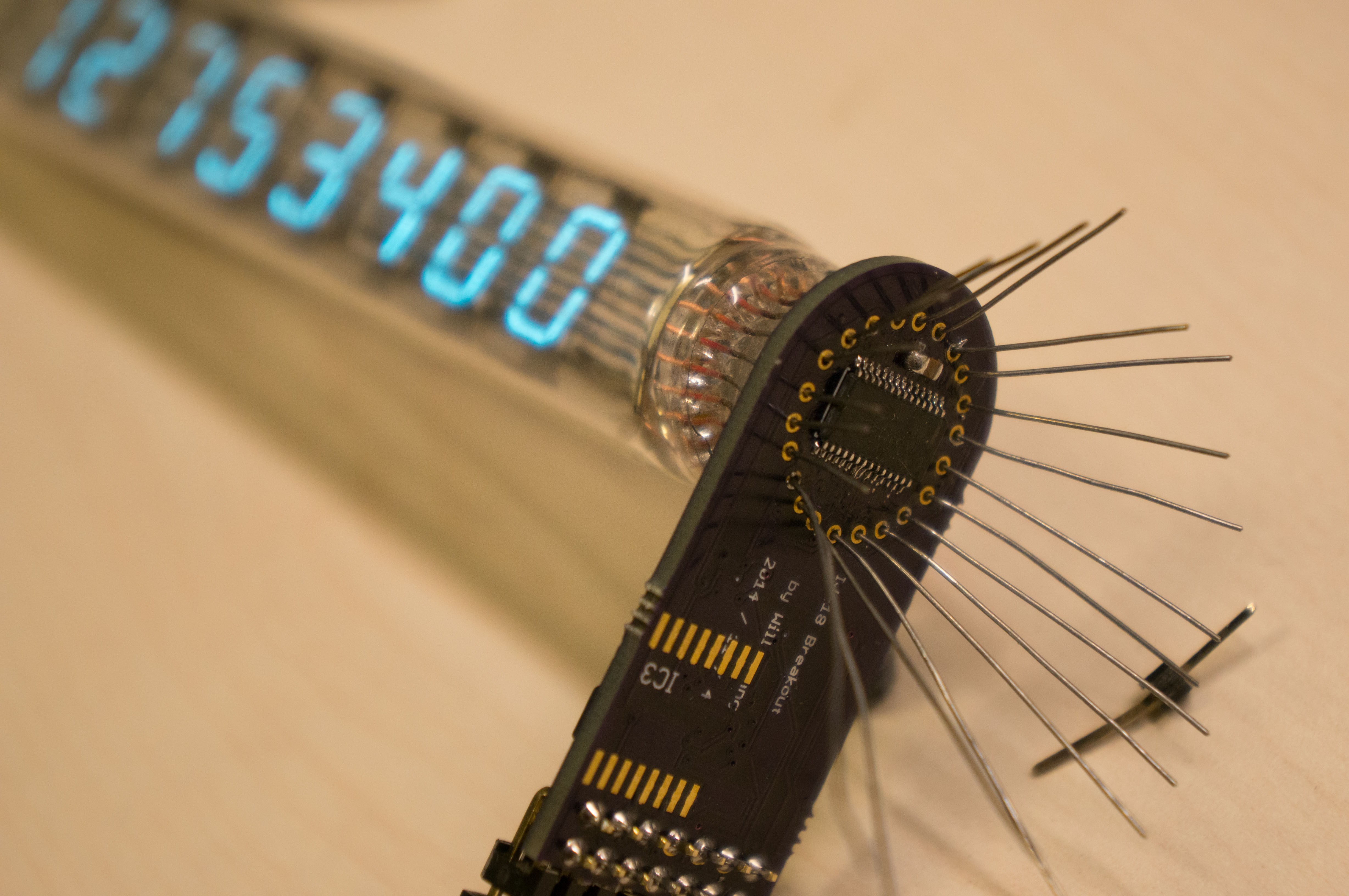
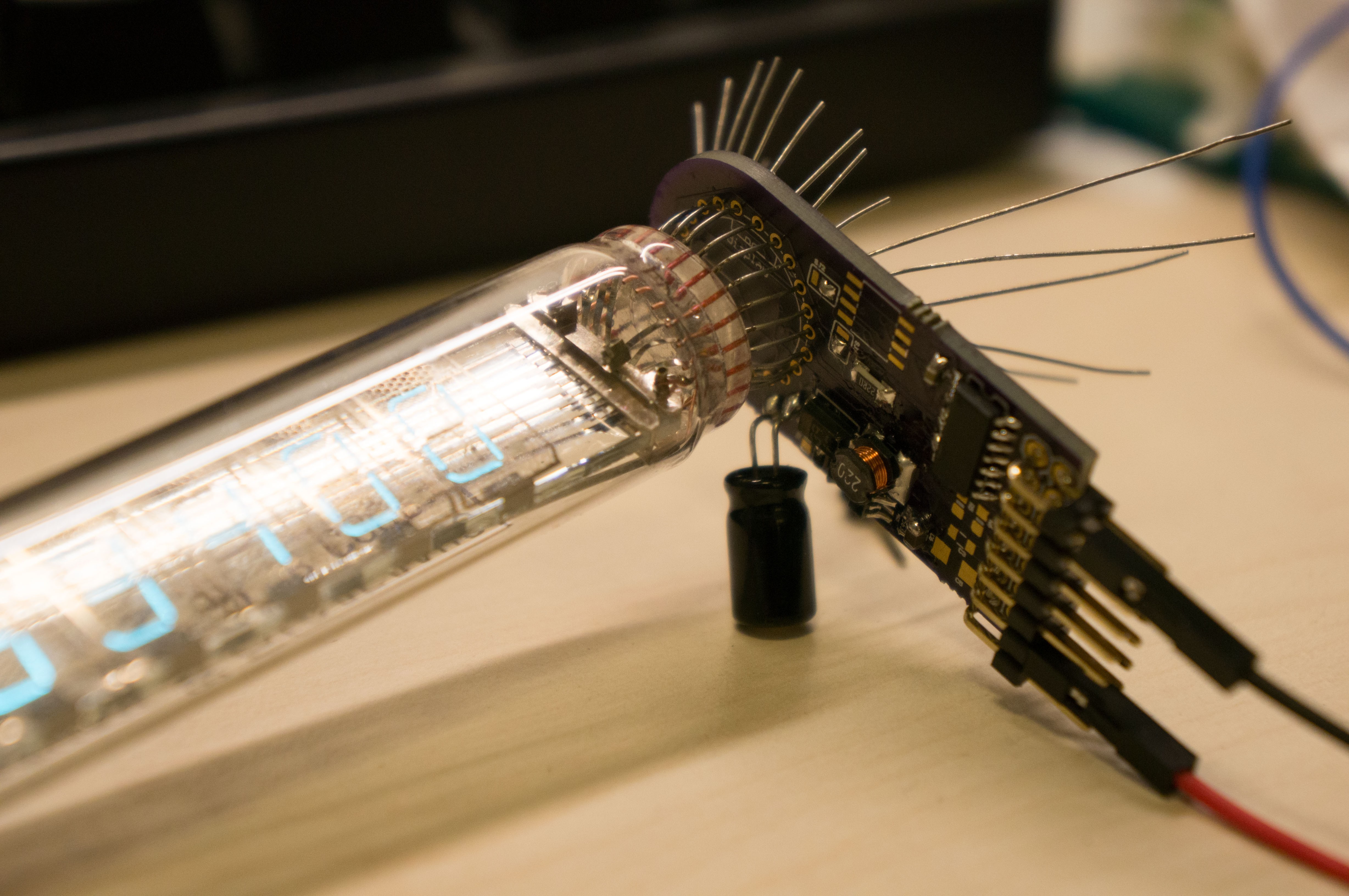
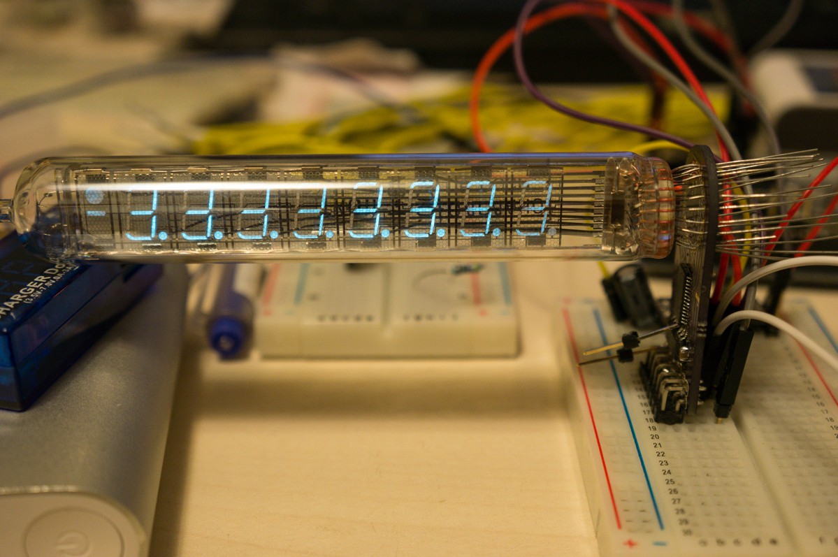
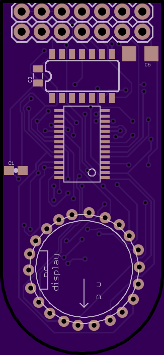
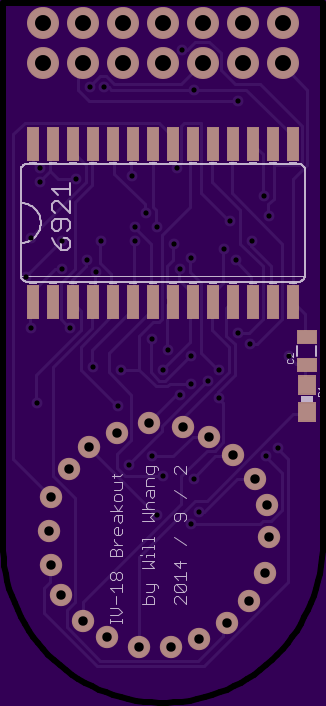
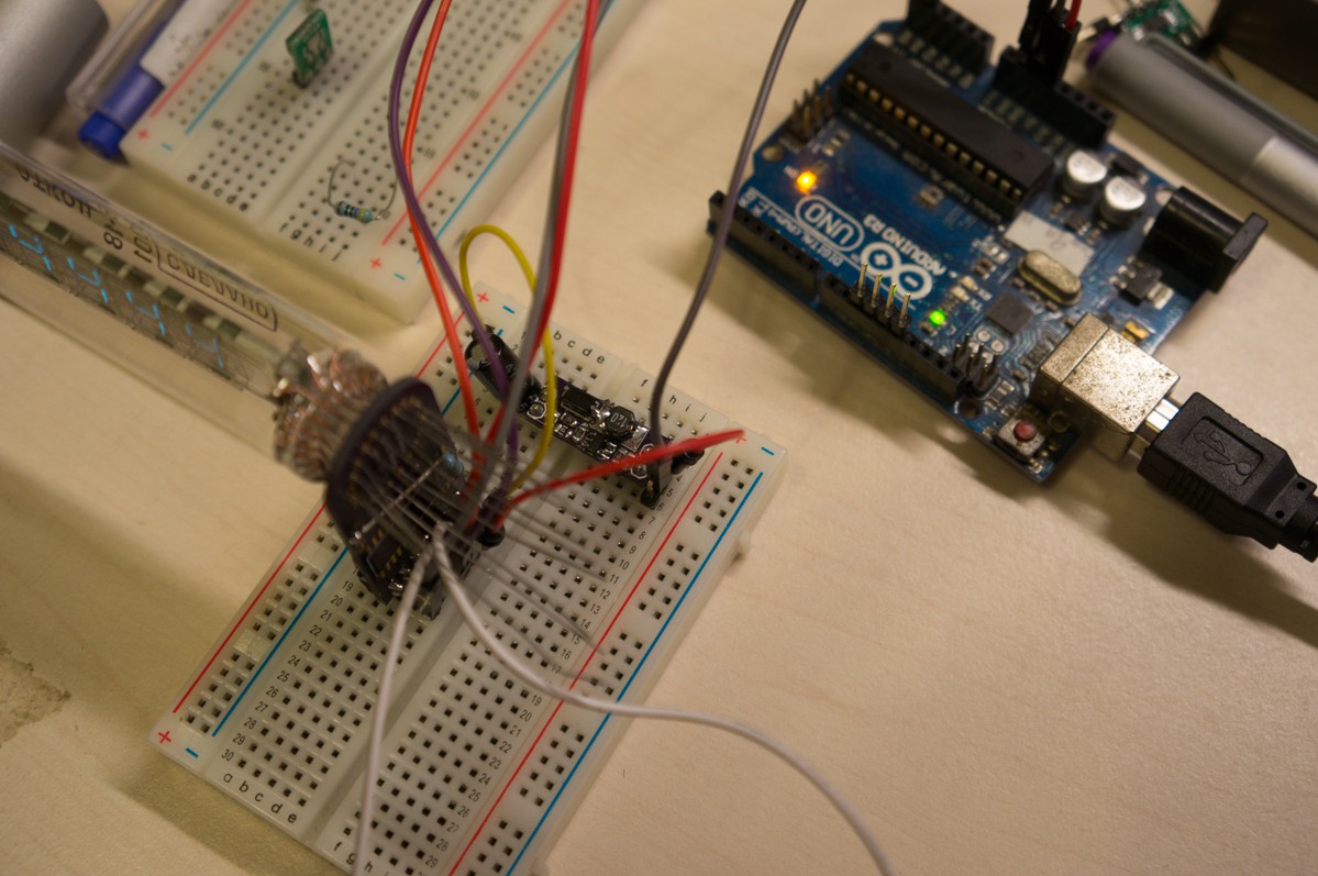
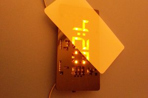
IV-18 Arduino Clock
Clock build from IV-18 VFD tube and Arduino
Become a Hackaday.io member
Already have an account? Log in.
Just one more thing
To make the experience fit your profile, pick a username and tell us what interests you.
Pick an awesome username
hackaday.io/
Your profile's URL: hackaday.io/username. Max 25 alphanumeric characters.
Pick a few interests
Projects that share your interests
People that share your interests

 George Albercook
 Giulio Pons
 David Brown
Cool job!
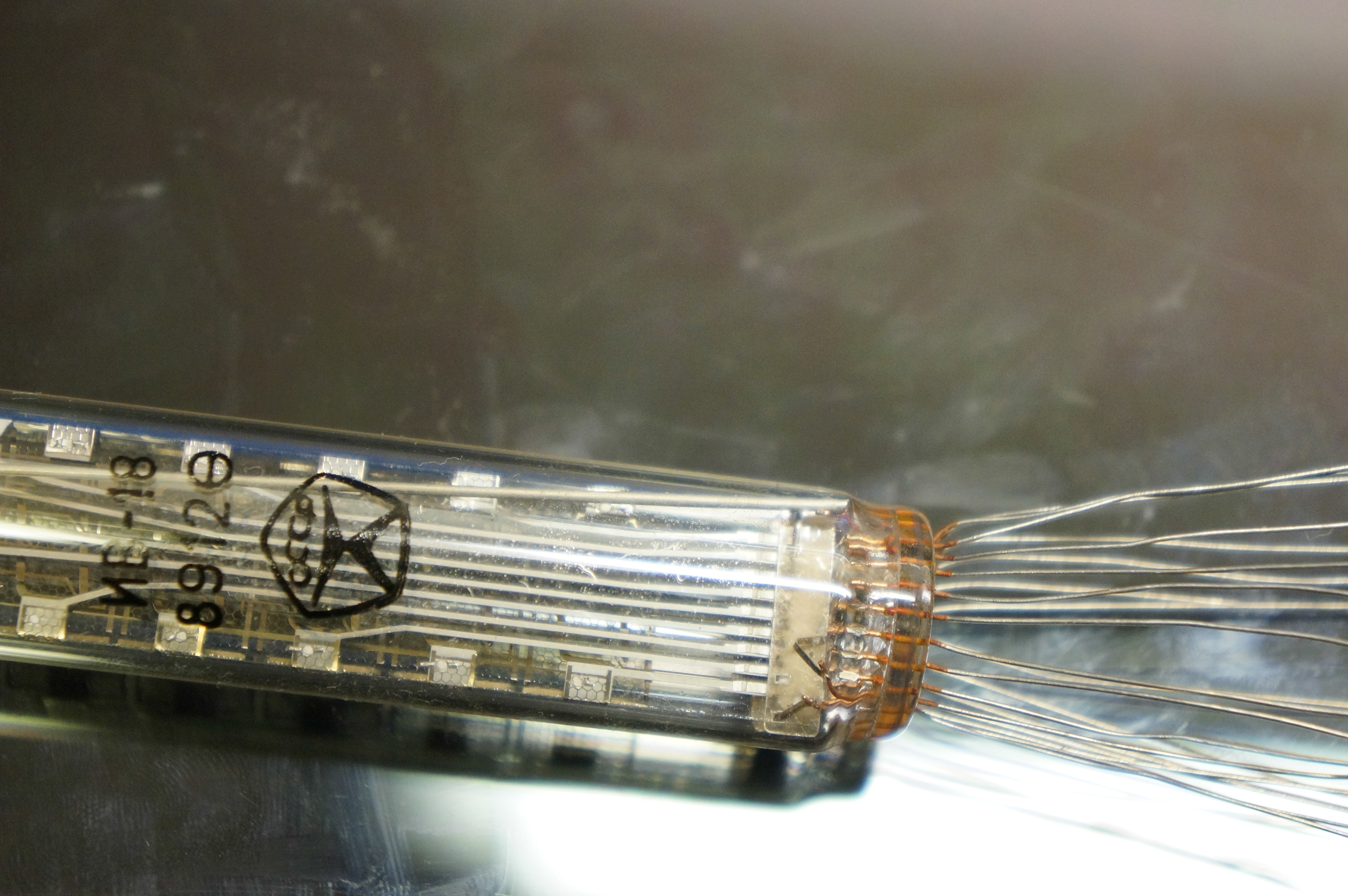
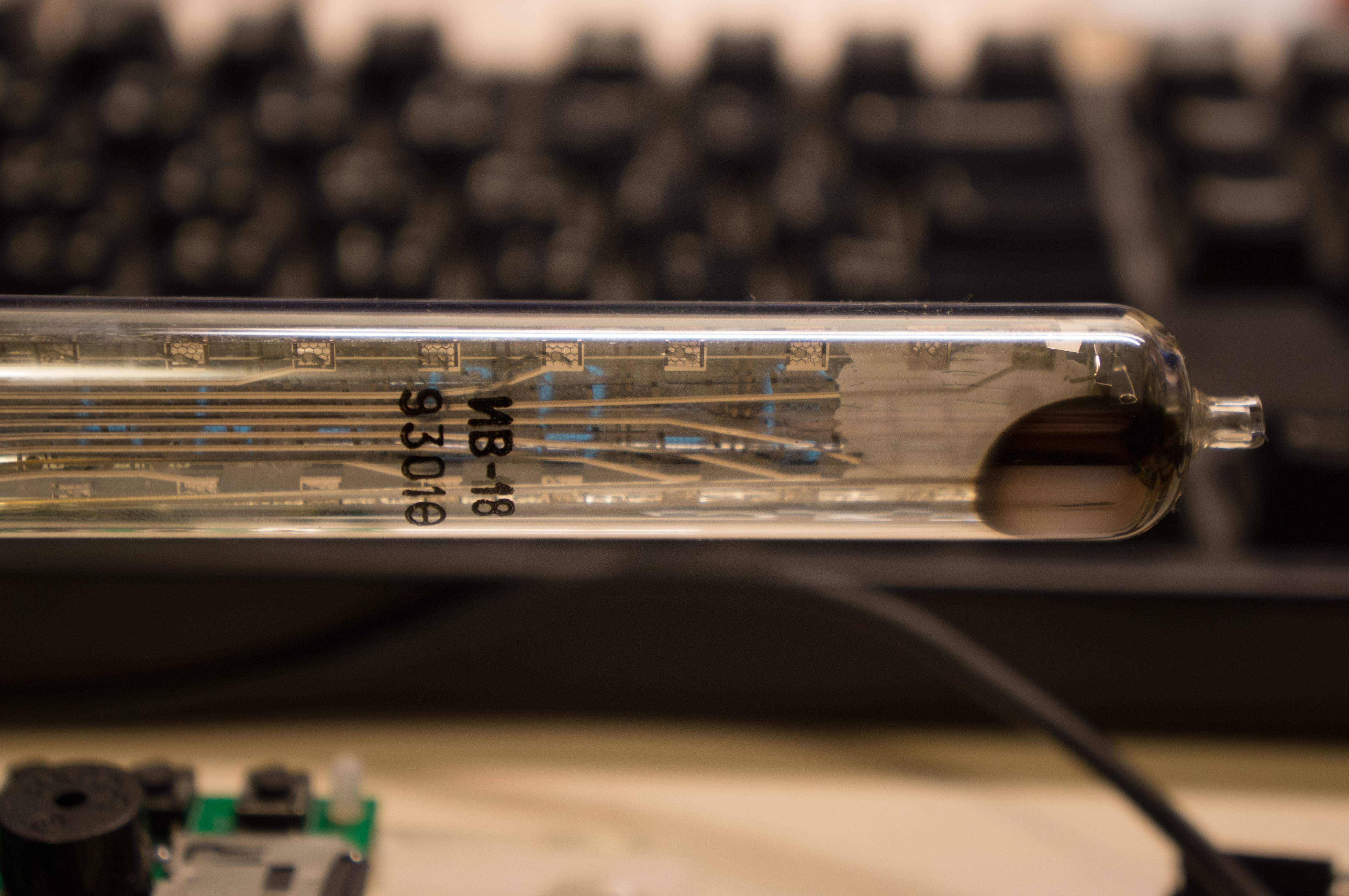
some note^_^ both tubes its civil grade :) its quality ussr mark for civil goods :) but tube from 93 make in after soviet period and not reason for marking that. Actualy im from Ukraine and have many this and other tubes if you need :) https://www.ebay.com/usr/g_titov