 Eric Jacob
This project started simply as a need. We needed a simple low cost CNC platform for general use. I really prefer to have standalone machines. While I could switch out the bits and platform on my handmade CNC router, I would prefer to have a small machine that is always setup for PCB routing. From this stemmed the idea to use this base for other standalone machines, such as a pink-n-place, or a 3D printer. Having a cheap platform would allow us to realize this possibility.
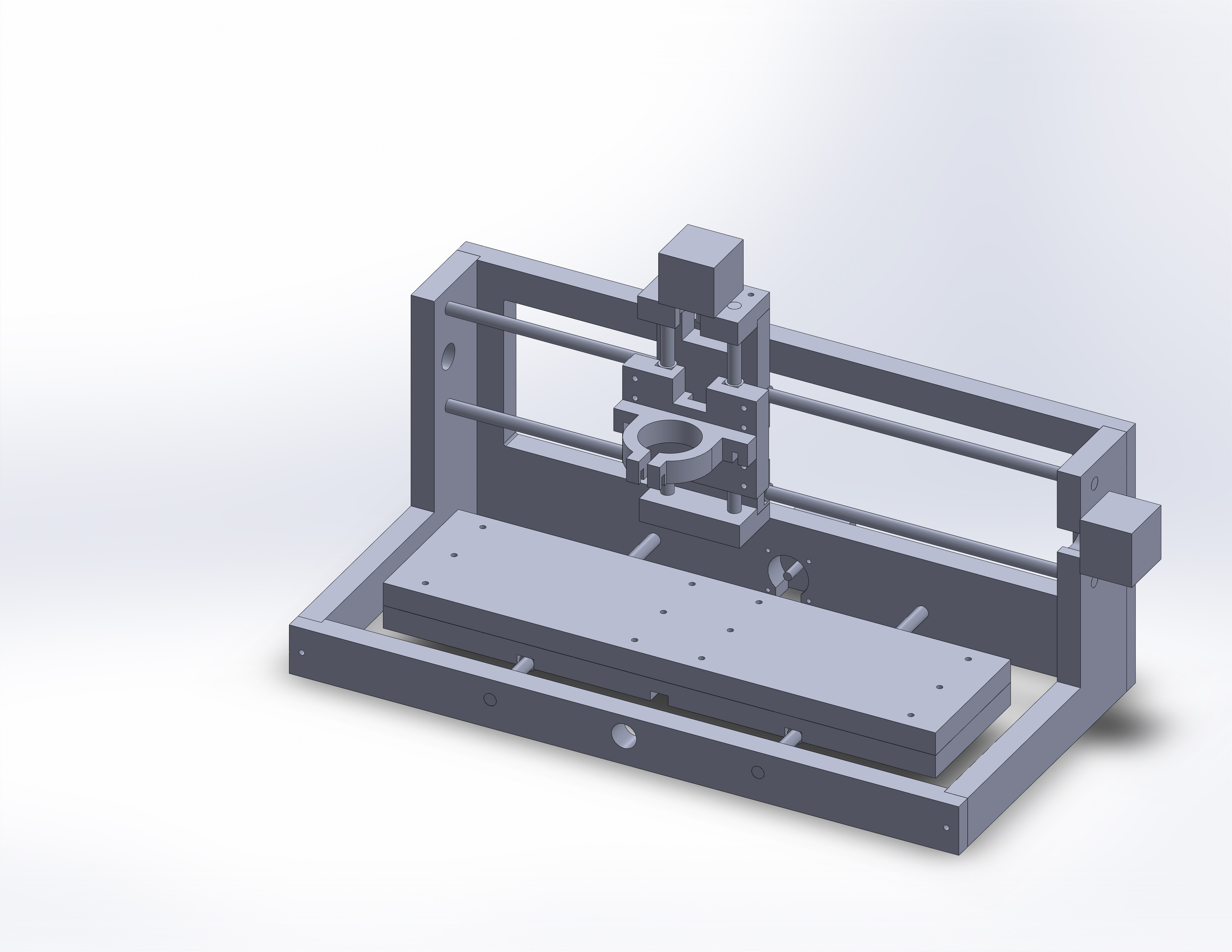
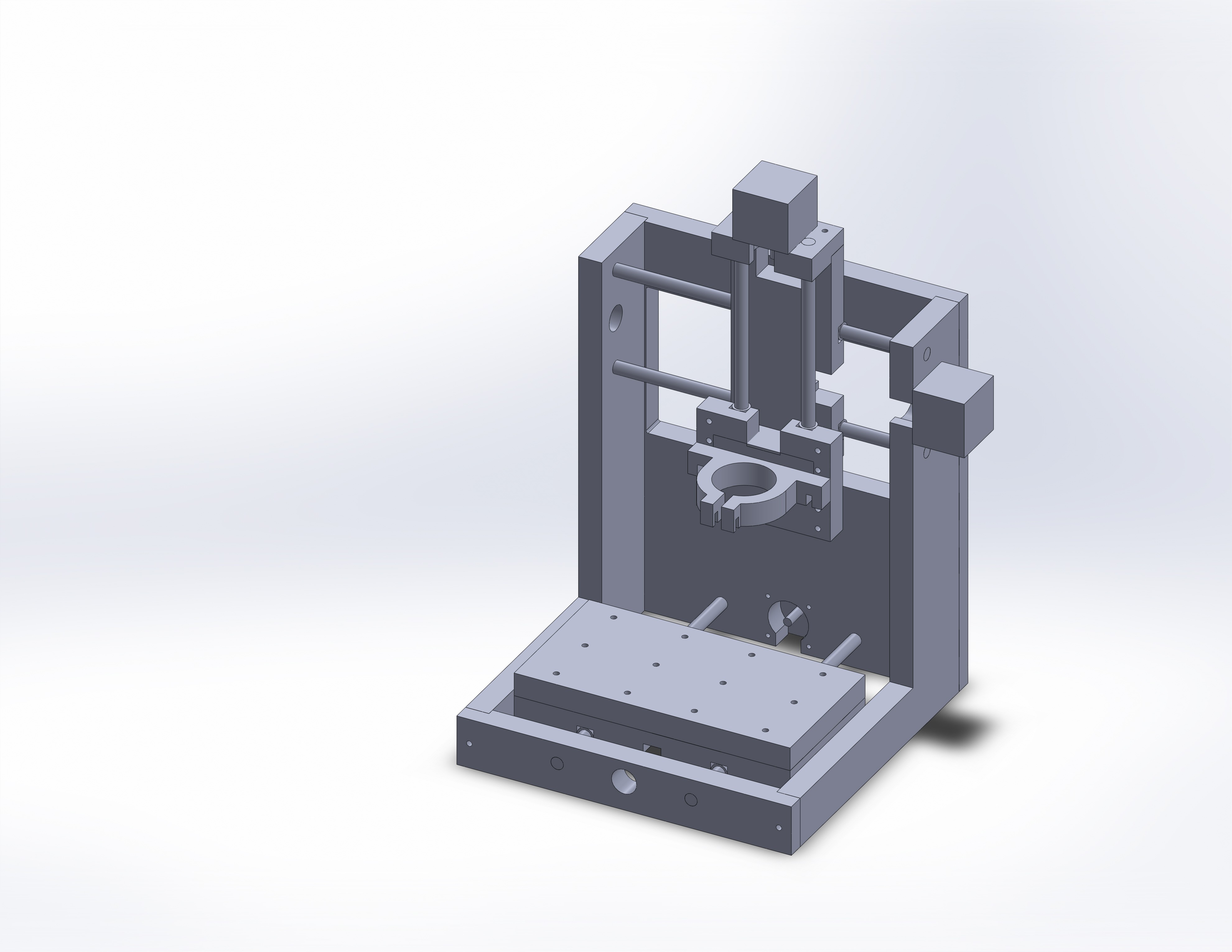
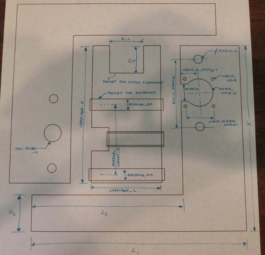
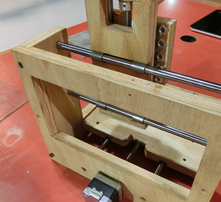
Pulling from other open source designs, we laid out the drawings for version 1. From there we iterated, changing small things like the way the bearings attach to the base. We added features, like groove to line up parts. Cut outs around the motor to make servicing easier, and so on. This lead us to the latest version.
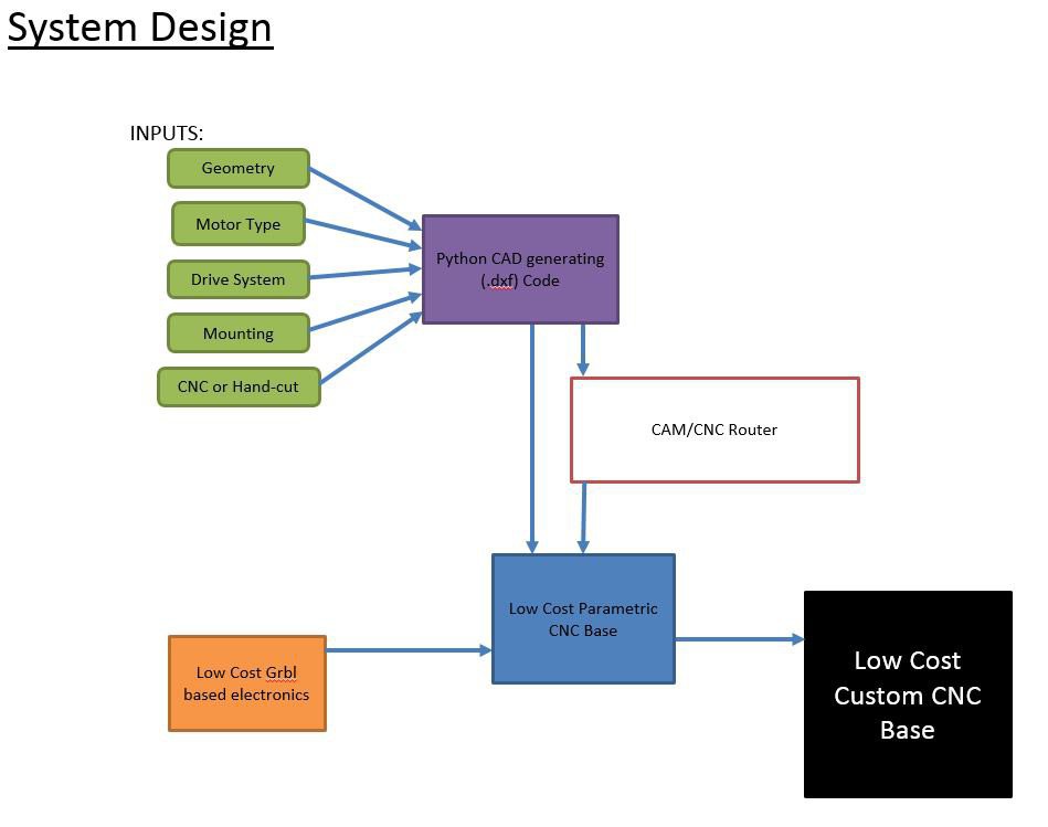
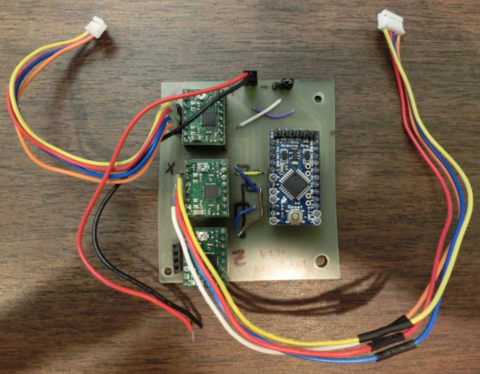
In addition to the mechanics, again, pulling from other sources, we identified a simple electronics framework to use with the low-cost platform. We've laid out a arduino based g-code interpreter (grbl) with pololu drivers. This gives us functionality using already functioning open-source software. In order to reduce cost, we've laid out an single PCB with arduino and stepper drivers. (CNC shields are also an option).
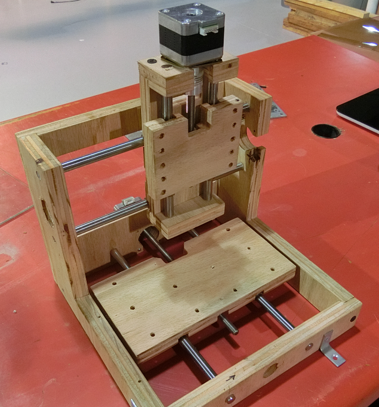
Here we get a functional small scale CNC for under $100 in parts.
Later I tried to adapt our design for use as a 3D printer. With 3D printing you are looking for other charateristics in your CNC base, than with a mill. In a mill we want ridigity, speed is nice, but not critical. In a 3D printer rigidity is important, but no significant forces are being applied to the extruder head. The mass of the head should be kept down so that speeds can increase. Also, low cost threaded rod drive systems may not provide the speeds required.
Furthermore, the CNC we had laid out was just quite not big enough. While we could individually tweek each design for its needs, that is time consuming. What if we instead wrote a script that would auto generate the CAD drawings for the design requirements. Key dimensions could be input. Continuing this thought, other parameters like, threaded rod or belt driven could be flagged, or NEMA motor size, therby changing the motor mountings or other dimensions.
While the time to create a code like this would be of the same order as just tweeking a few designs that we need, the savings going forwards, as well as the usefulness to the community would be far greater. And that is ,after all, the great power of the internet and why I can leverage other open projects to get to here quickly.
The electronics design is independent of the mechanics, but it is added here to show the full interconnectedness of the project. If required, other control systems can be used.


 Mike Machado
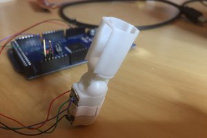
 Tim Wilkinson
 Gabriel D'Espindula
 Christophe Machet
Which NEMA motor did you go with?