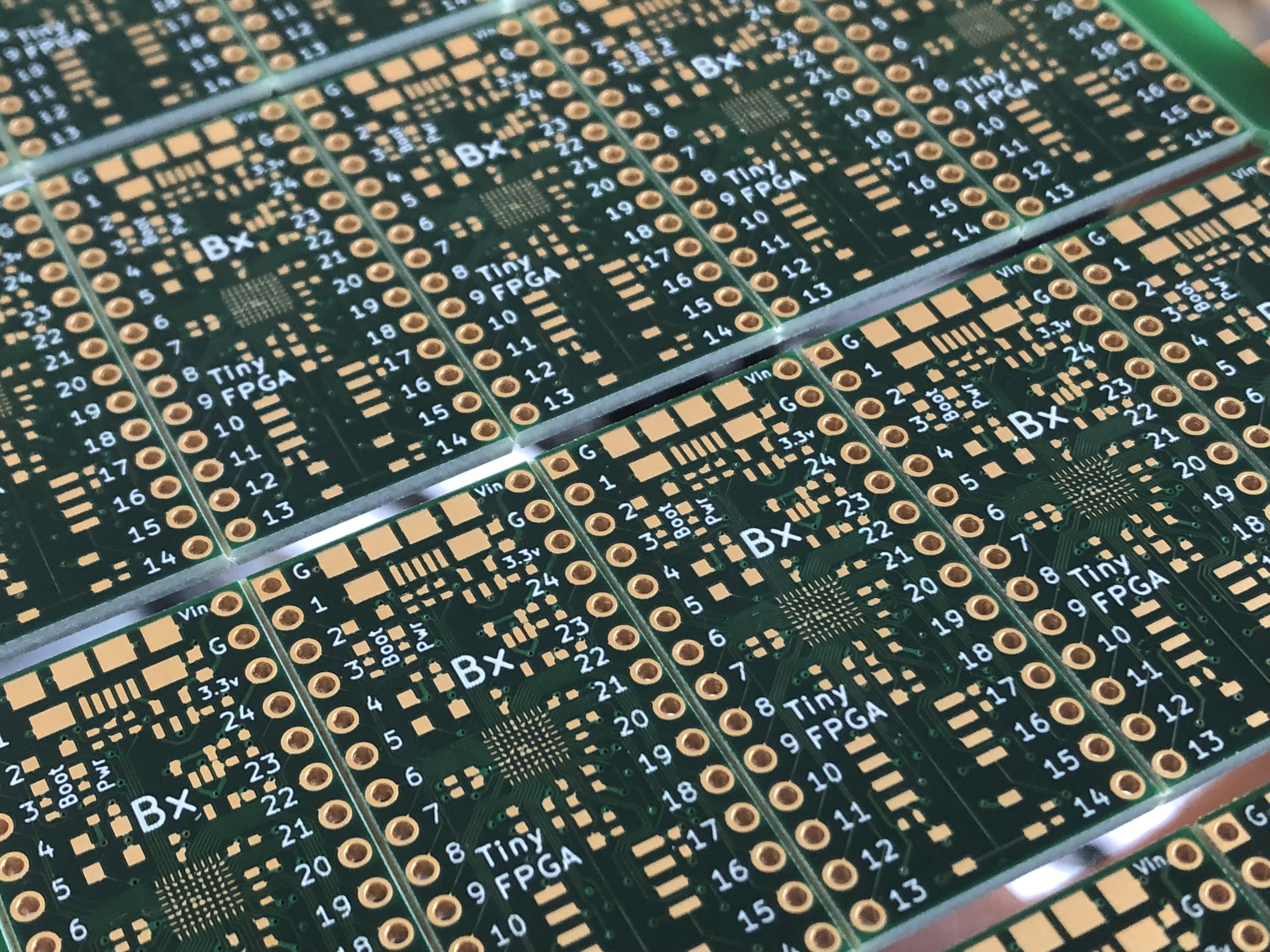
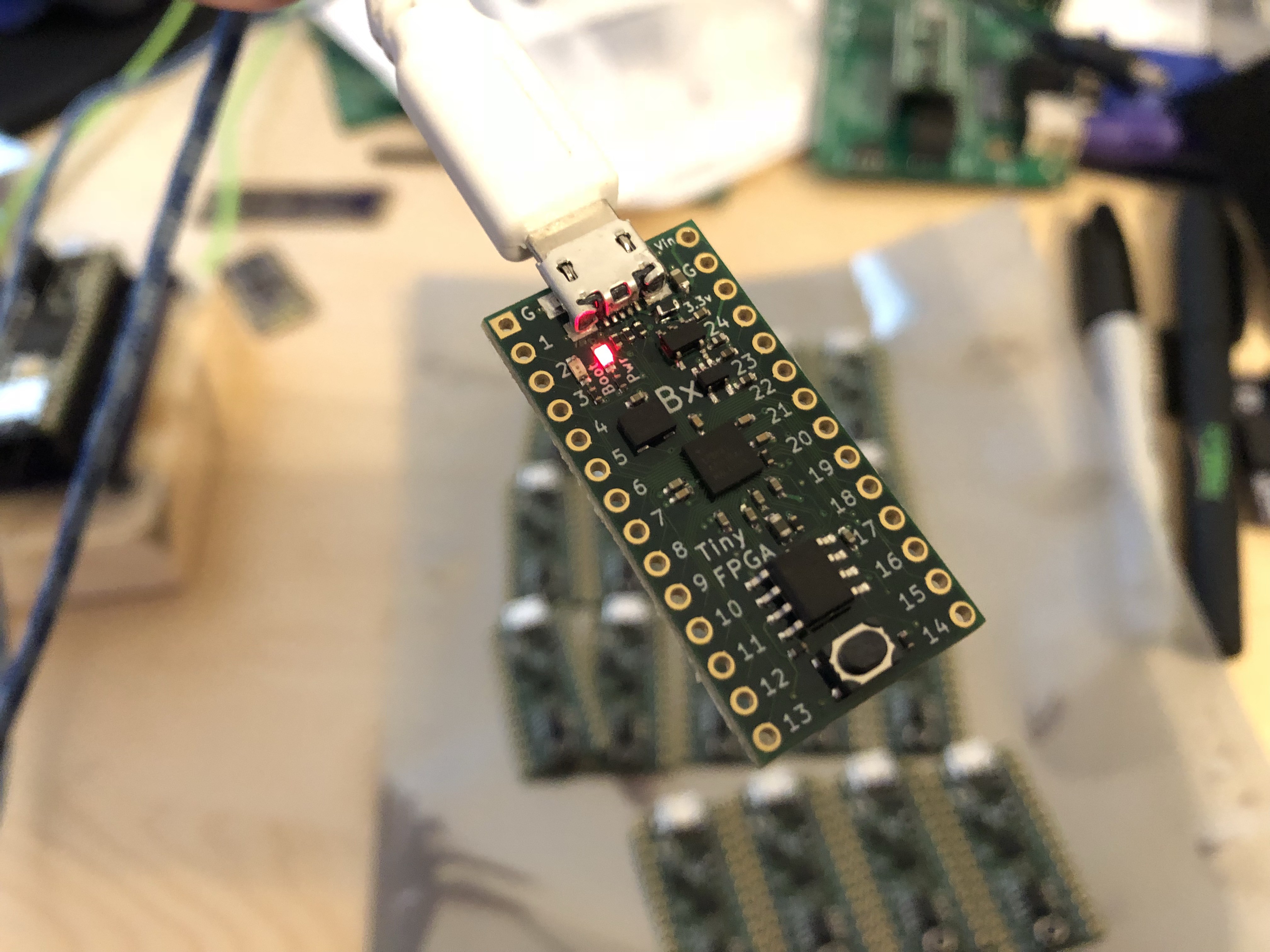
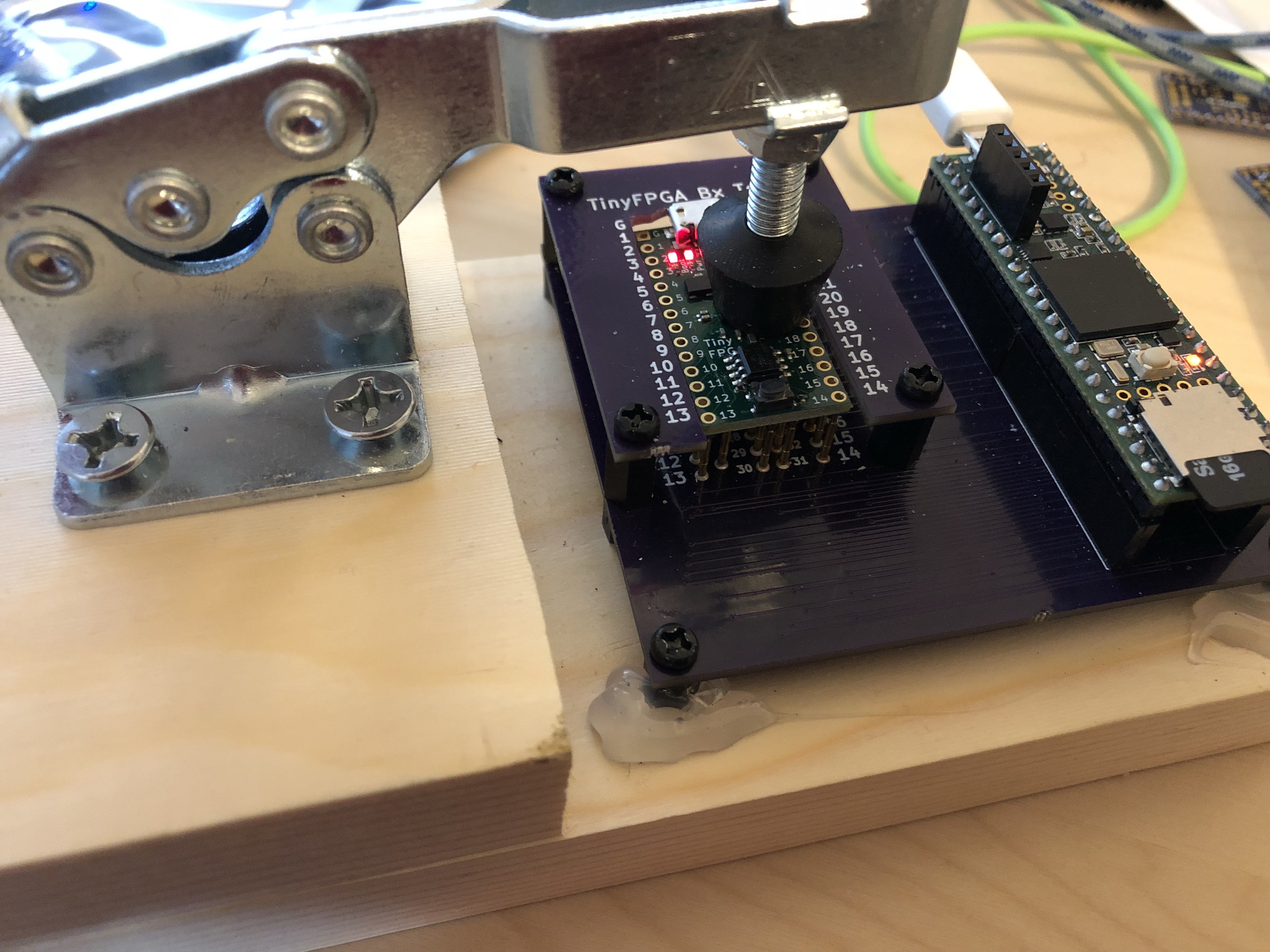
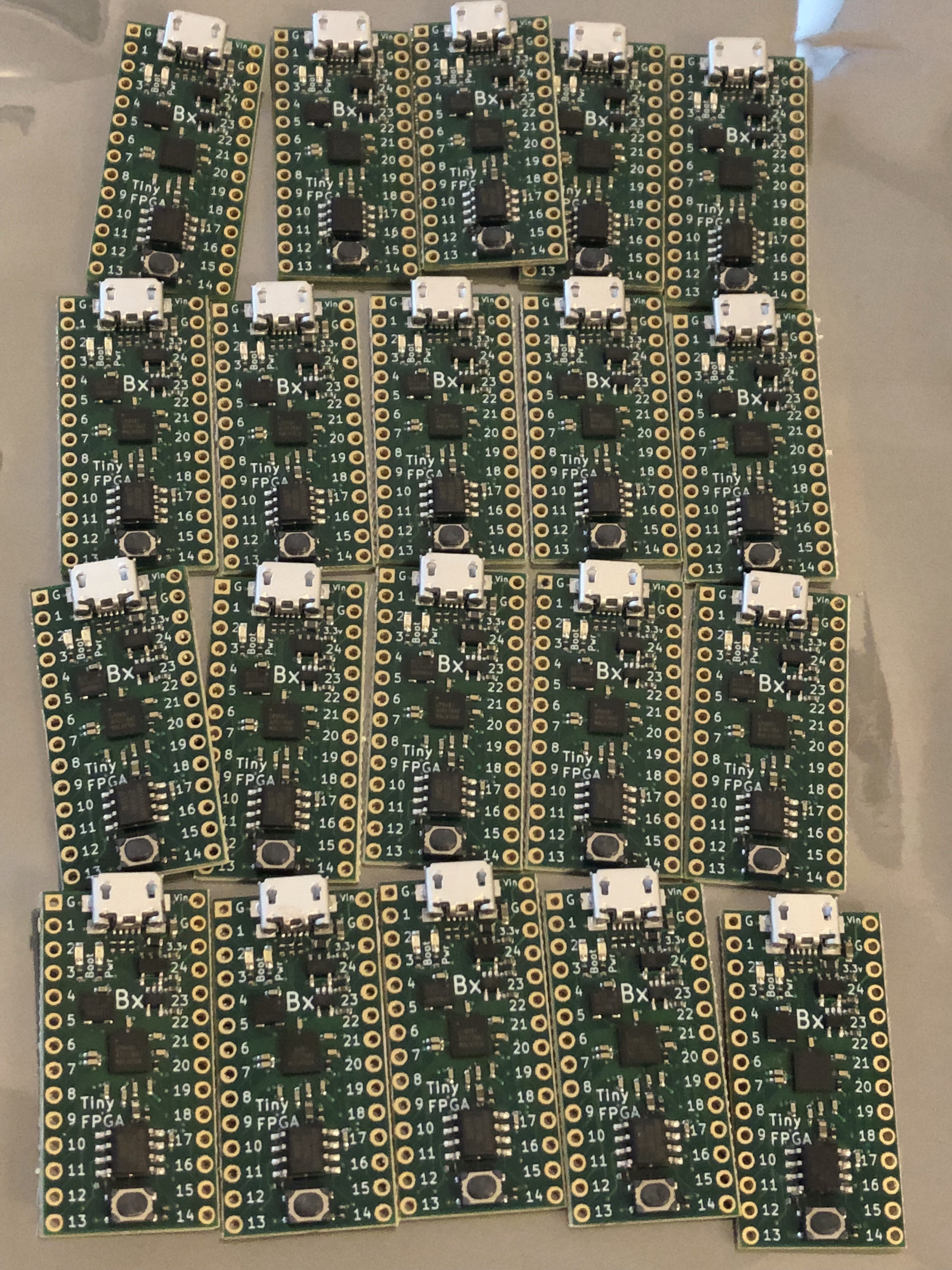
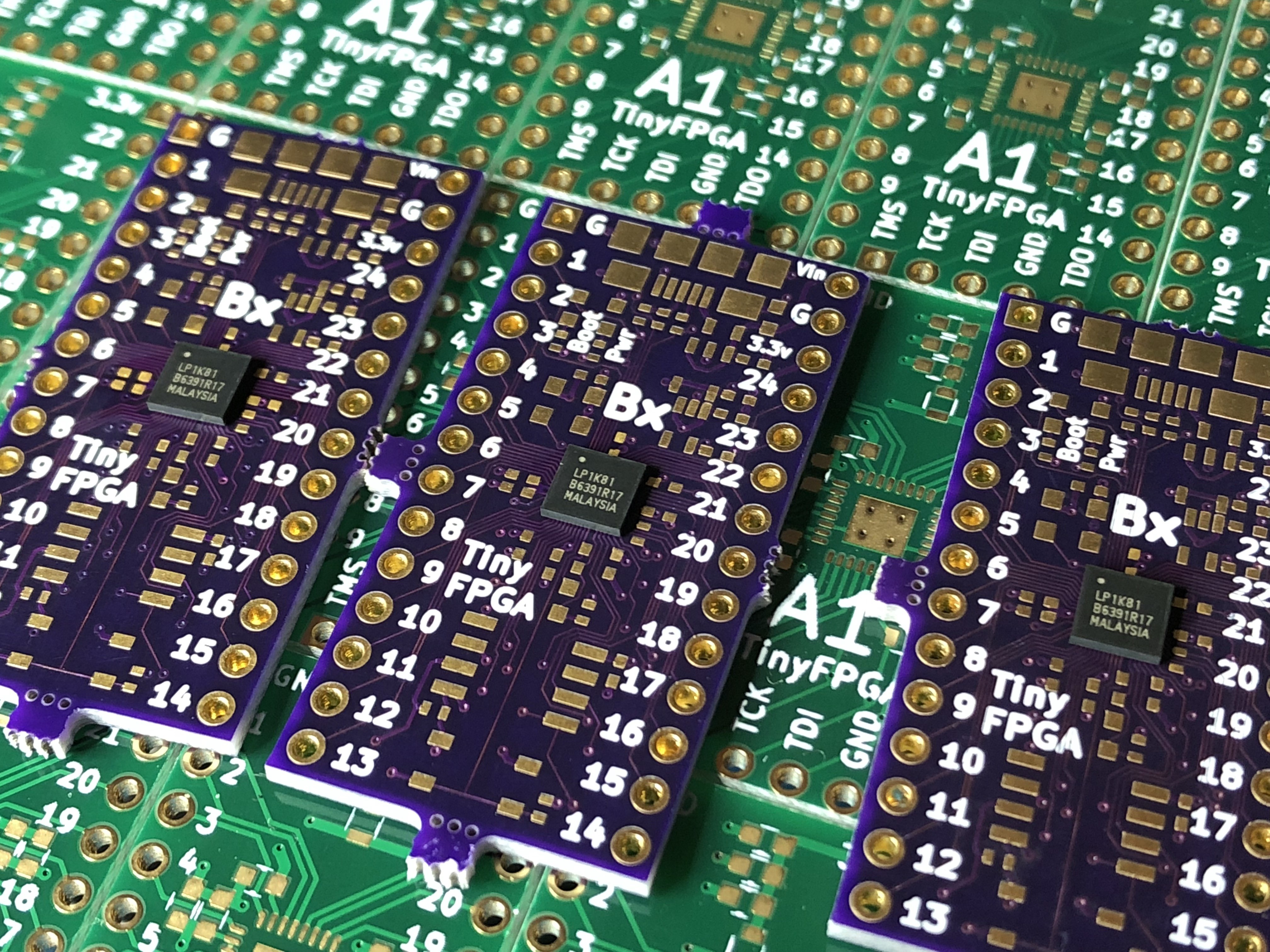
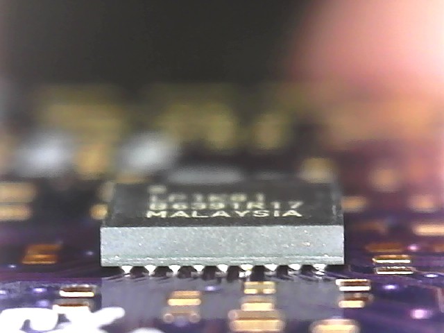
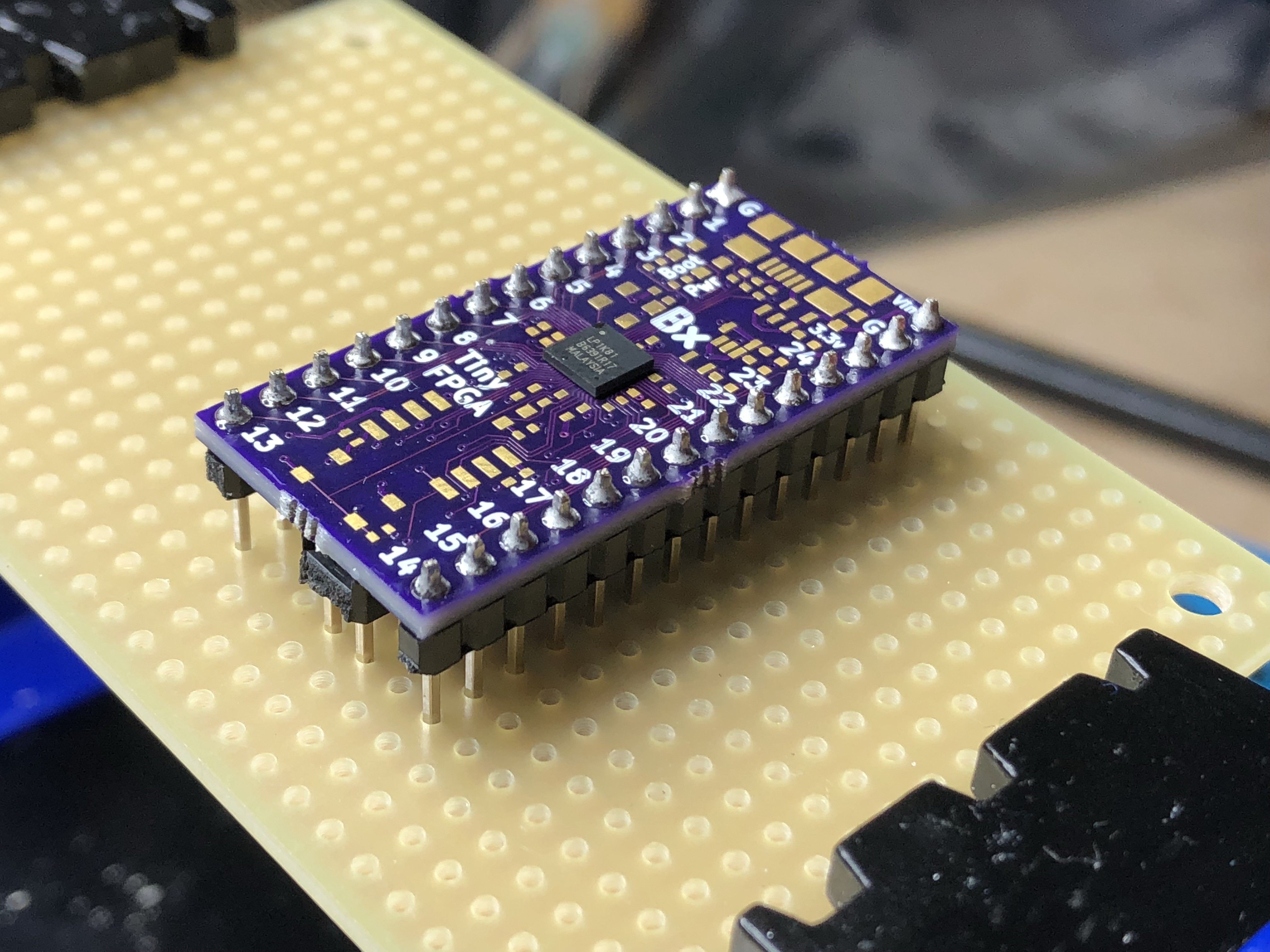
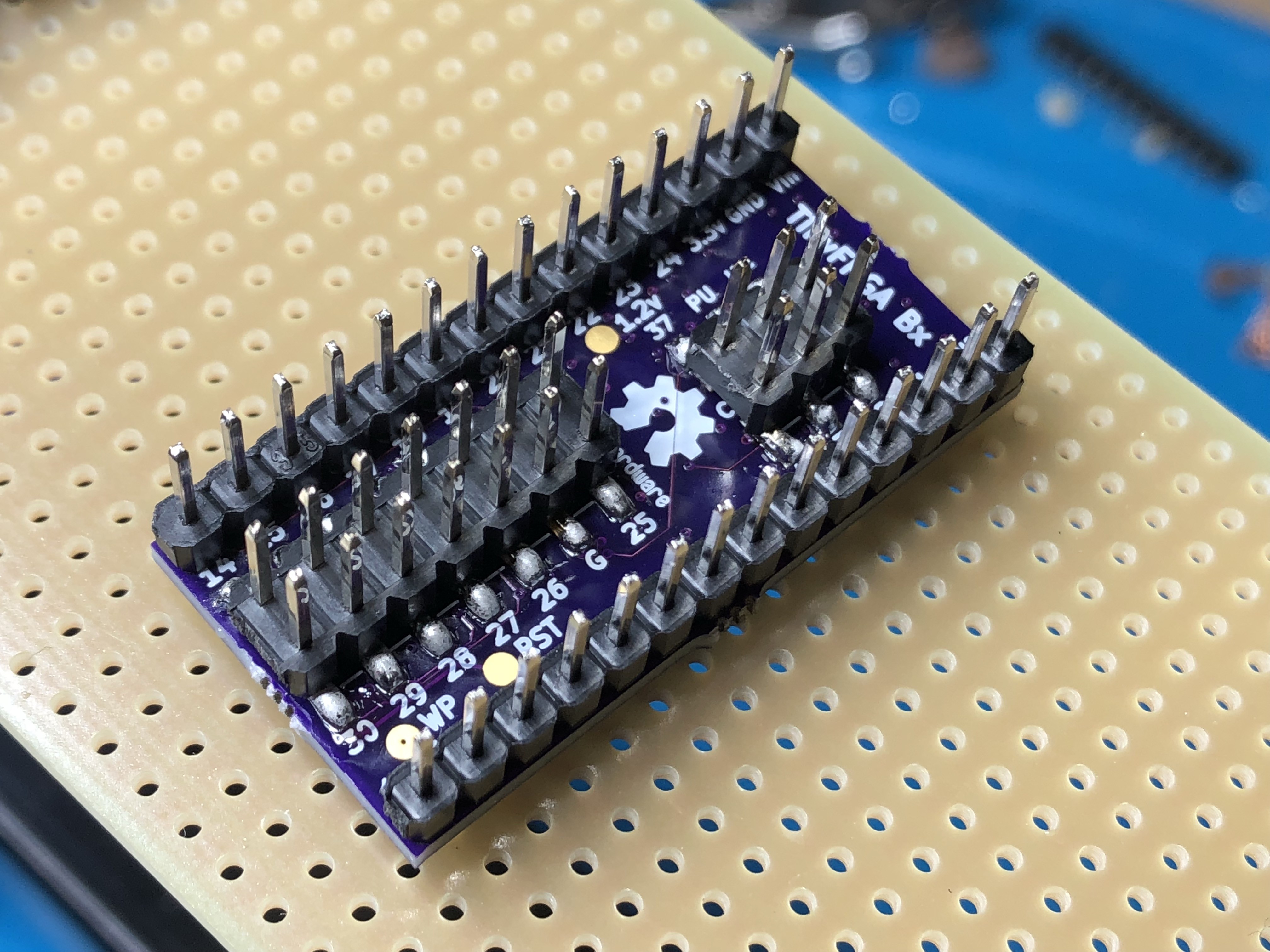
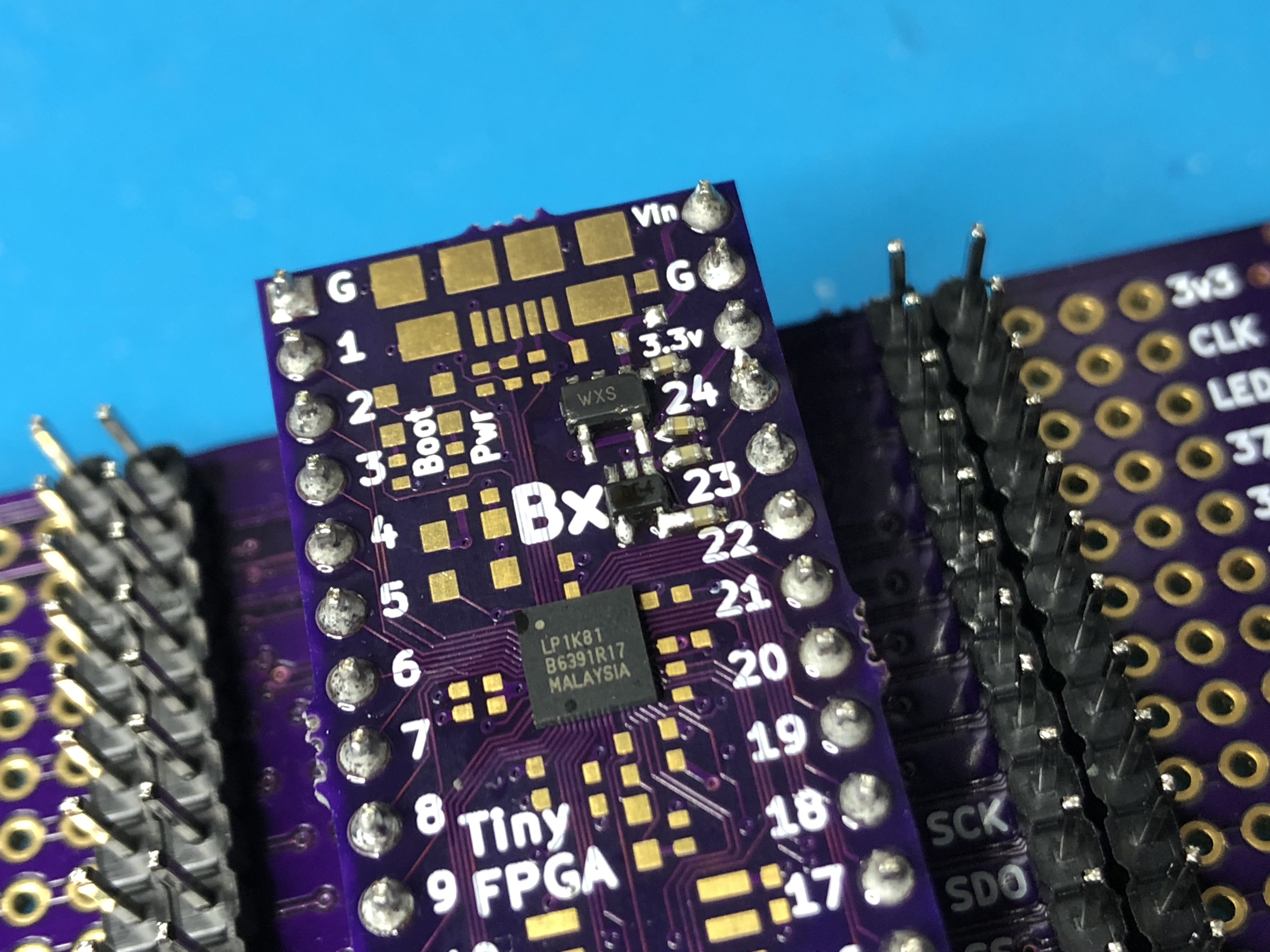
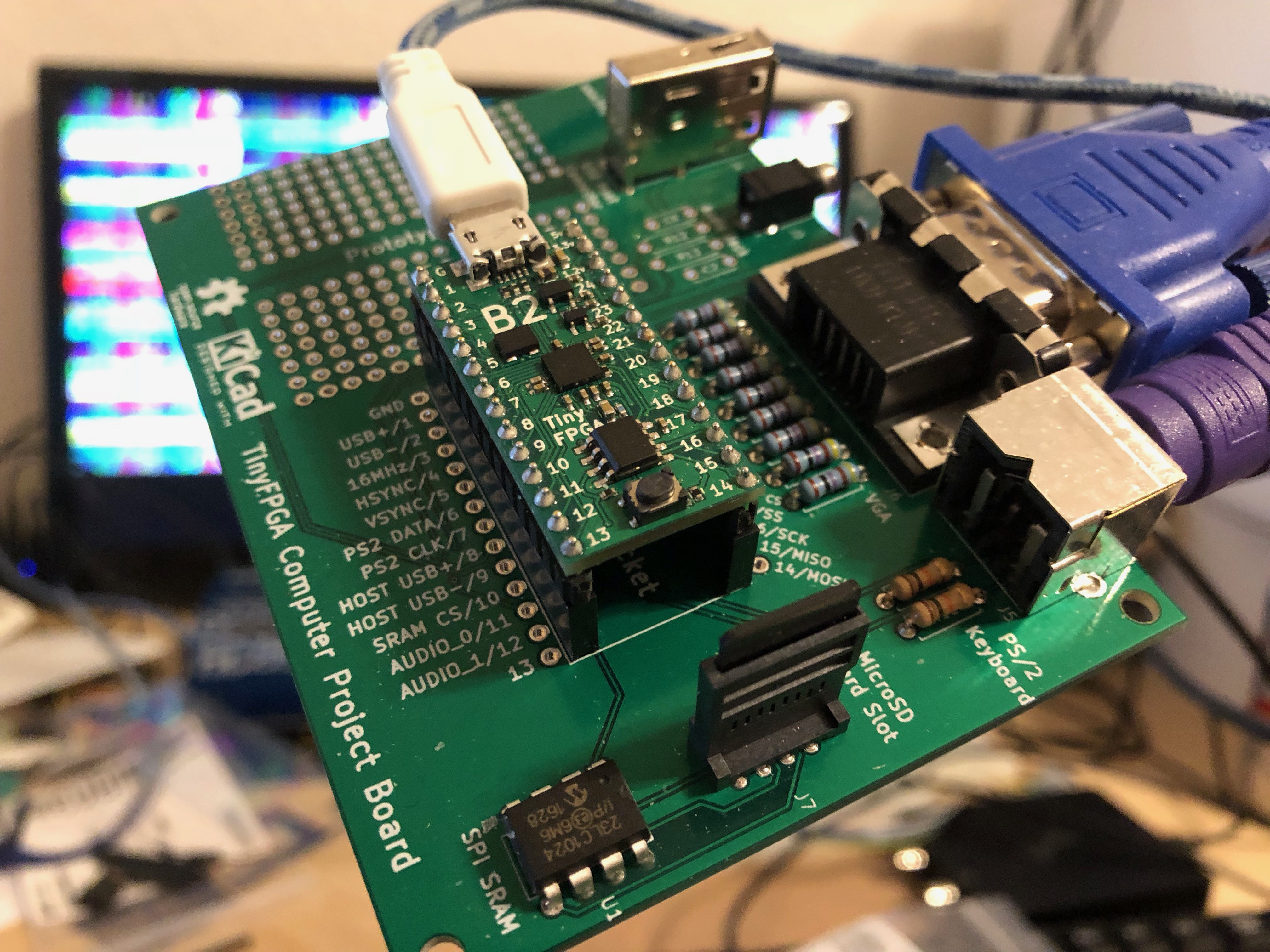
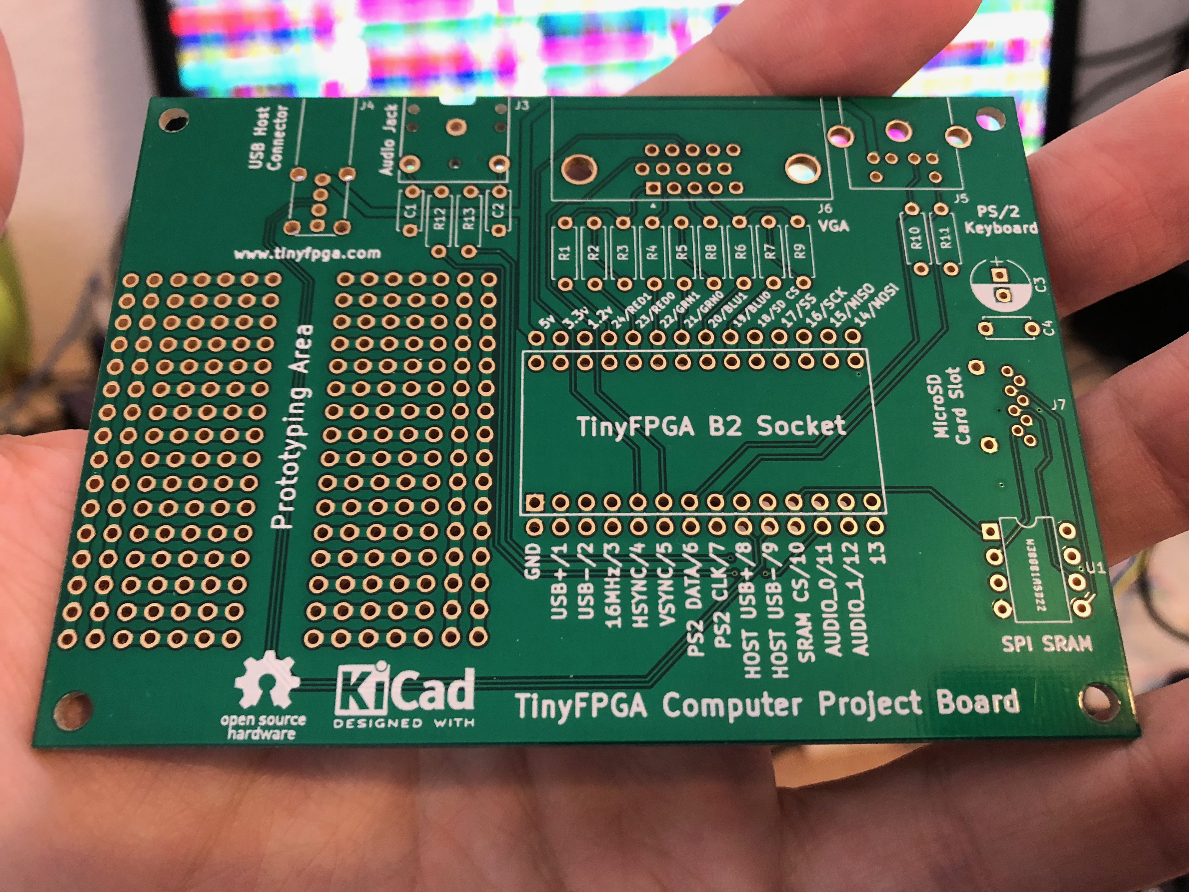
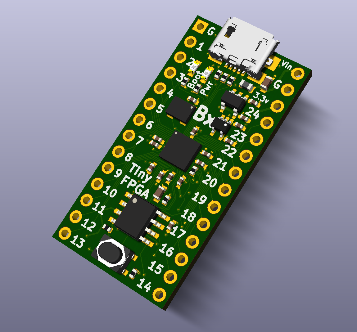
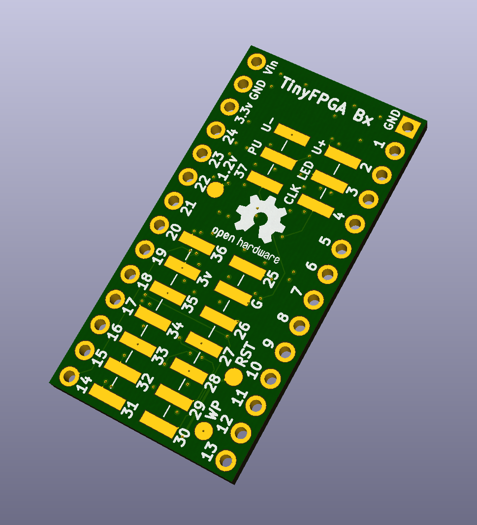
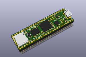
• TinyFPGA BX Pre-production Prototypes

    Luke Valenty01/27/2018 at 18:21 0 comments

    I received the TinyFPGA BX pre-production boards a few days ago and have been putting them through their paces.  It's all good news so far.  I found and fixed a few bugs in the tester firmware and updated the bootloader to use the controllable pull-up resistor and indicator LED.  

    I broke out all the boards from the panel and tested each one.  Every single one passed.  All 42 FPGA IOs, 16MHz clock, voltage regulators, and SPI flash are functional on all 20 boards.  This means that the TinyFPGA BX project is GO!  

    This success is a big deal.  If you've been following me on Twitter (@tinyfpga) or the logs on this project you know that the BX prototypes are testing a non-standard BGA footprint for the teeny tiny iCE40 FPGA.  This footprint allows me to fan-out twice as many user IOs from the FPGA, but it does not follow the recommended guidelines for BGA packages.  Getting 20 boards successfully manufactured and assembled gives me confidence that a full production run will have acceptable yield.

    I have some plans to clean up the bootloader some more.  There are a few bugs that I would like to fix as well as some features to make the "program, test, program, ..." flow more fluid for the user.

    If you are interested in buying a TinyFPGA BX stay tuned, I will be launching a campaign on Crowd Supply in the coming weeks.  

  • Working BX Prototypes!

    Luke Valenty01/15/2018 at 08:00 3 comments

    I had a very exciting few days as I received some TinyFPGA BX prototype boards from oshpark.  I didn't really think I'd be able to assemble these first prototypes.  I had expected that it would be too difficult to reliably reflow the FPGA onto the new footprint.  I also wasn't sure that the boards would be high-enough quality since I was pushing the design to the very limits of what oshpark can do.

    So I scrounged up my USB microscope and took a look at the PCBs just for fun.

    Ohh my glob.  They are perfect.  Each one of the 6 prototypes I received from oshpark are absolutely immaculate.  This was the first time I ordered 4-layer boards from oshpark and I am impressed.  The soldermask pull-back is just 0.05mm.  That's just 50 microns.  The circular pads are 200 microns in diameter and the pill-shaped pads are about 330 by 100 microns.  I realized these boards were good enough to try out.

    I had a bad experience using solder-paste and a stencil when I assembled the original B2 prototypes.  It was very difficult to get a clean print and then it was difficult to get a reliable reflow.  This time I decided to use nothing but flux and a hot-air gun.  The flux goes on footprint spread thin, then the BGA package, then the hot air.  It took about 30 seconds to reflow.  The first board I reflowed using this method was sacrificed for science.

    I wasn't sure how well the balls would reflow onto the footprint so I hacked away at the assembled board to get a good shot of the balls.

    Looking at the balls we can see one solder ball on the left edge and two on the right edge that are on circular pads.  The rest of the balls are on pill-shaped pads pointed towards the camera.  You can clearly see the difference in shape.  The balls seem to be reflowing onto the pill-shaped pads very well.

    I tried sanding and cutting into the BGA package itself to try and get  a cross-section of some balls.  This didn't work out too well as debris was pushed underneath the package and the solder balls may have been pushed around.  

    Talking about this on Twitter, there were a few suggestions from the community on better ways to analyze BGA package reflow issues.  Without an x-ray, the best option seems to be dying the area under the package and letting it set before pulling the package off vertically.  If there is dye covering any pad then you know you have an open.

    My next step was to assemble some boards by hand. 

    I started out by reflowing the FPGAs onto three boards.  Without cutting into the board I was still able to spy some very promising connections on all four sides.

    This was getting very exciting.  I believed this footprint would be very risky, but each board was turning out better than expected.  I was interested in testing the basic functionality of the FPGA and the connections to all of IO pins.  Testing this basic level of functionality meant that I could pick and chose the critical set of support components necessary to breathe life into the chip.  This ends up being the two voltage regulators, their capacitors, some bulk capacitance, resistor for PLL VCC, and the SPI flash.  Since I would be assembling these few boards by hand this would save me a lot of time.

    I also decided that the first order board I had to bring-up would require a lot of debugging.  So I soldered on a full set of BX pins so I could put it into a special breadboard designed for the BX boards.

    The breadboard has all of the IOs routed out to their own rows.  I soldered on some headers that my logic analyzer and lattice programming cables could attach to.  This provided a nice platform for first bring-up.

    Here's a close-up of the voltage regulators:

    The mini "testbench" with the programmer and logic analyzer connected.  The blue wire is soldered onto a test-point used to hold the FPGA in reset.  This...

    Read more »

  • New retro computer project board using the TinyFPGA B2

    Luke Valenty01/07/2018 at 17:45 0 comments

    I've posted details about a new retro-computer project board using the TinyFPGA B2.  Check it out on the Hackaday.io project page: https://hackaday.io/project/29526-tinyfpga-computer-project-board

  • TinyFPGA BX Prototype Production Status

    Luke Valenty01/03/2018 at 06:38 0 comments

    The TinyFPGA BX prototype boards are currently being manufactured.  The PCBs have been fabricated and are now waiting for assembly.  I should get them back in a couple weeks.  At that point I'll be checking them out and developing the pogo-pin tester firmware.

  • New BX Revision (with caveats)!

    Luke Valenty12/25/2017 at 07:06 1 comment

    I've been working on a new revision to the B2 board.  I am running low on my B2 board stock and need to manufacture more boards.  I've been making some big changes that I think will be very welcome improvements on the B2:

    • More IO pins!  Up 42 IO pins can be controlled by the FPGA.  33 of those IO pins are dedicated to user IO and are not shared with the USB port, LED, or SPI programming interface.
    • LEDs!  There is now a power LED and a bootloader LED that can also be re-purposed by the user.
    • Better USB!  The USB pull-up resistor is now controllable by the FPGA.  This means the USB connection will be more reliable after programming the FPGA and when entering the bootloader via the reset button.
    • Double the SPI flash!  The SPI flash chip has been upgraded to 8MBit from 4MBit.  This gives more space for user data like programs to be executed on a soft CPU core.
    • Teensy 3.2 compatible foot-print (mostly).  The main footprint is compatible with the Teensy 3.2.  You can stack a Teensy 3.2 and TinyFPGA BX board on top of each other and not worry about shorting out any pins.
    • More power and ground pins!  There are now a total of 3 ground pins and 2 3.3v pins.
    • Dedicated power and ground layers in the PCB!  The PCB is now a 4-layer PCB with dedicated ground and power layers.  This should help improve high-speed signal integrity.
    • There will now be just the BX board.  The B1 was going to use a smaller capacity FPGA, but it wasn't cheap enough compared to the B2 that it never made sense to manufacture.  So now the BX will supersede the B2.

    I'm very happy with these changes and have ordered 20 assembled prototypes.  I'll be posting updates as the boards come back and are tested.  I may sell a limited number of prototypes ahead of a bigger manufacturing run.

    Sounds great, so what's the caveat?  Well...the B-series TinyFPGA boards have always used an unconventional BGA fan-out.  The iCE40 parts they use have a tiny 0.4mm ball pitch and this makes them very difficult to use without moving to a very expensive PCB process.  This is not a problem for their target market of mobile devices, but does present some challenges for hobby FPGA boards.

    The new BX boards are able to fan-out significantly more signals due to a change in how the outer pads are shaped on the board.  They've been elongated into a pill shape to allow for some inner signals to be routed out.  This is not standard and there is a risk that it won't work out.  

    I believe there are enough regularly shaped pads to align the BGA balls properly over the pill-shaped pads along the perimeter.  This self-alignment along with solder paste on the pads will ensure good contact.  The pill-shaped pads have the same surface area as the regular pads, but have a longer perimeter.  I believe this will increase the surface tension slightly and may pull the package very slightly closer to the PCB.  This should be OK since the layout of the elongated pads is very symmetrical.  The BGA package should still be pulled down evenly and should retain the self-alignment properties of a regular BGA footprint.

    This is partly why I ordered 20 prototype boards fully assembled from my PCBA manufacturer.  I should be able to get an idea of the yield based on this small run.  I'm feeling pretty good about the chances and am very excited for the prototypes to be delivered.  Stay tuned!

  • Bootloader Protocol

    Luke Valenty10/11/2017 at 05:43 0 comments

    I've documented the bootloader protocol a bit more in the GitHub repo: https://github.com/tinyfpga/TinyFPGA-B-Series/blob/master/bootloader/README.md

    If you want to integrate the TinyFPGA B-series into a development platform, you can ideally use the tinyfpgab.py programmer script instead of writing your own.  However, there are some cases where it's just not practical or user-friendly to do so.  In those cases this README should help along with the reference implementation that tinyfpgab.py provides.

  • Open Source FPGA Synthesis Tools (and CLI!)

    Luke Valenty10/10/2017 at 06:42 0 comments

    I have pushed an update to the TinyFPGA B-Series GitHub repository with a template for the open source icestormFPGA synthesis flow.  Take a look at the new README for detailed instructions.

    I've also added support for programming TinyFPGA B-series bitstreams using a command-line interface.  Take a look at the READ for instructions on using the command line interface.

  • Schematic PDF Available

    Luke Valenty10/07/2017 at 03:11 0 comments

    I've finally gone over the schematics of all my projects and organized them a little bit so they are nice and easy to follow.  For people that don't have KiCad installed, making the schematics available in PDF form is much more convenient and easy to share for quick reference.

    You can view the PDF directly on GitHub: https://github.com/tinyfpga/TinyFPGA-B-Series/blob/master/board/TinyFPGA-B.pdf, or you can take a look at the image included below.

    I've also started a new Hackaday.io project, #The Hobbyist's Guide to FPGAs.  I'll be posting articles, tutorials, and hands on labs using the TinyFPGA boards as project logs.  If this sounds interesting to you then follow the project to be updated when new content is posted.

  • Quantity Pricing

    Luke Valenty09/29/2017 at 02:47 0 comments

    Quantity price tiers have now been added for the TinyFPGA B2 on the Tindie store.  For larger orders or resale please contact me directly at luke@tinyfpga.com.

  • Getting Started Guide Updated

    Luke Valenty09/14/2017 at 13:53 0 comments

    I've updated the getting started guide to include installation of @Paul Stoffregen's  Virtual Serial Driver Installer if you use a version of Windows older than Windows 10.  If you ordered a TinyFPGA B2 board and are planning on using an older version of Windows, you will need to install the driver in order to program the board.

    Windows 10 has a brand new USB serial port driver that works for all CDC class USB devices (USB serial ports).  Older versions of windows don't do this because some devices aren't exactly compliant to the CDC class driver and needed special workarounds.  The new Windows 10 USB serial driver gets around this by relaxing its standards a bit and letting devices misbehave a little bit.  This allows them to default to using the universal driver.  Paul's installer installs an INF file that tells windows that any CDC class USB device that doesn't already have a driver specific to its VID and PID can use the generic USB serial port driver.  

    Paul went through all the work to make this installer and get  it signed.  Not only does it work for his Teensy boards, it also works for everyone else that makes a generic USB serial device with a different USB VID and PID.  Thanks Paul!