Close
0%
0%

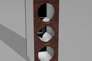
Aluminium Delta Effector

Delta's are great but the fan on my one keeps hitting one of the towers so I decided to do a few upgrades.

Similar projects worth following
Well my delta was working great until the ball ends wore out. I ordered a new set and found they were a little loose for my liking. Then decided to make my own using some high quality ball ends, M3 threaded rod and the original carbon fiber tube.

After making the rods as with all alterations came the... how can i improve things..

So the next part was to design a new effector, while doing that I also decided to tackle the issue I had with the fan hitting one of the towers and causing me to loose about 20mm of print space on one side.

If anyone is keen on a copy of the cad files I used or wants them as an STL feel free to fire me a message and will see about posting them.

  • Creation of the Effector

    Boris van Galvin09/01/2017 at 01:10 0 comments

    Hunting around the workshop I found some 10mm Aluminium plate, I creates a model and machined it out on the CNC machine. 

    Once this was done I hand filed the ends where the arms attach so as to ensure there would be enough clearance for the sides of the ball joints and then tapped them all with an M3 tap.
    I really should check my taps as the one I grabbed from the M3 box was a UNF tap and as I started to tap out the hole in the first one I made it snapped off :( 

    At this stage I was tempted to build a small spark eroder to remove the broken tap but the printer has been offline for way too long and machining a new plate effector was going to be a little faster.

    Once the top plate was done I chucked it in the lathe to reduce the height a little more. Initially I was going to make the thing 10mm but the clamp that holds the J-Head in place was a little tight so bringing it down to 8mm allowed for a bit more clearance as well as reduced the weight a little.

    Machined the top collet to hold the J-Head and inserted an M3 grubb screw just to make sure that the J-Head would not twist. The tolerance is prety tight so there is no wiggle but as with most things made from ali eventually over time things tend to get loose.

    Then came the fan cover, this was machined from 50X50X4.5mm angle just because that is what I had in my bits box and a peice of aluminium tubing was cut bent and formed with a slot in it to match the seat cut in the top and bottom parts of the covers. 

    Initially I was going to just bolt it together but received some aluminium brazing rod a few weeks back so brazed the parts together. Its not super pretty but seems to be strong.

    There are 2 M3 rods that go from the base plate to secure the cover to the top of the effector. I could have used the J head to hold the cover in place but was a little worried that it may start to rattle over time and also did not want the thing to twist during use.

    Next on the list of things to do is work out how and where I am going to put the optical bed sensor and machine up a nice little copper block for the nozzle/heater etc.. The original ones that came with the J-Head do not have a split in them and the grub screw that holds the element in place tends to wiggle loose causing some interesting problems with heat stability.


View project log

Enjoy this project?

Share

Discussions

Similar Projects

Does this project spark your interest?

Become a member to follow this project and never miss any updates