 tomcircuit
CPLD glue all written in VHDL and includes CPU clock generation, baud clock generation, address decoding, and SPI master. A few "registers" were implemented in the CPLD to allow soft-configuration of the SBC. The address decoder allows the uppermost 16K of EEPROM to be banked over the EEPROM. The Zilog SCC Ch A provides a 115.2kbps interface to the USB host via the FTDI bridge. A Zilog 8536 Complex Input Output (CIO) device provides 20 I/O pins as well as timers and a clever interrupt controller. The USB B connector is the host interface as well as a means to power the board.
0%
0%
HD6309 Singleboard Computer
Hitachi HD63C09 clocked at a blistering 3 MHz with a capacious 64K of RAM! Retroputing bliss...
Become a Hackaday.io member
Already have an account? Log in.
Just one more thing
To make the experience fit your profile, pick a username and tell us what interests you.
Pick an awesome username
hackaday.io/
Your profile's URL: hackaday.io/username. Max 25 alphanumeric characters.
Pick a few interests
Projects that share your interests
People that share your interests


 Matthew Pearce
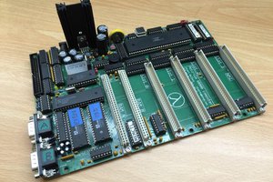
 Stuart
 Colin O'Flynn
 Keith
Keith
I know, according to your logs here you were looking at Flex for the OS, What about NitrOS-9.... written to take advantage of the 6309, flexible memory model iirc.... hardware treated as modules to the kernel... I believe it's open source as well.