Close
0%
0%

Electric Ninja

Converting an 05 Ninja 250R to electirc

Similar projects worth following
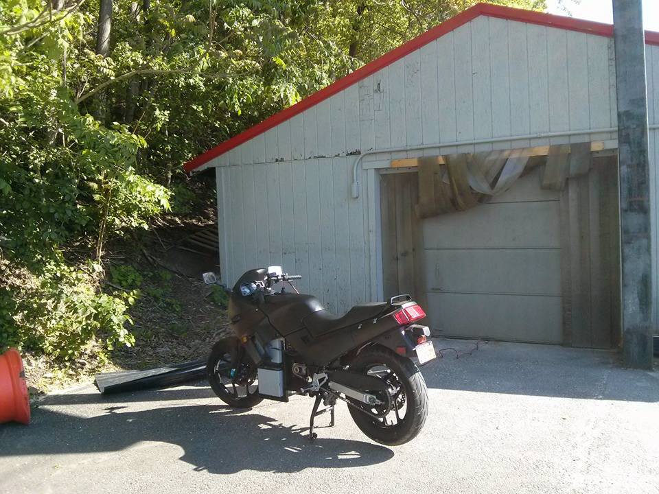
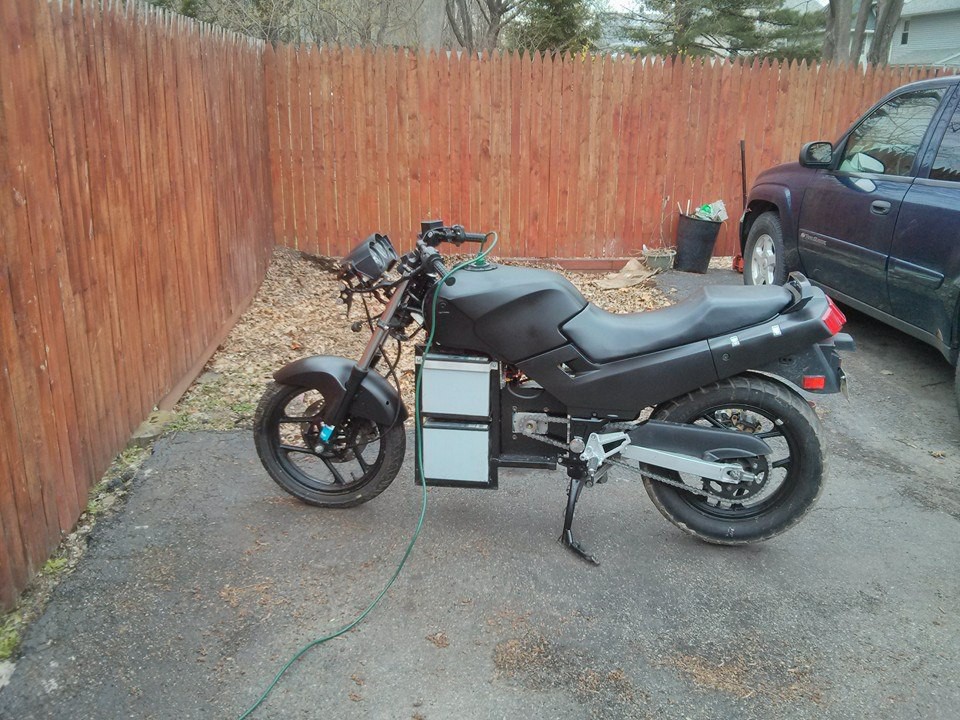
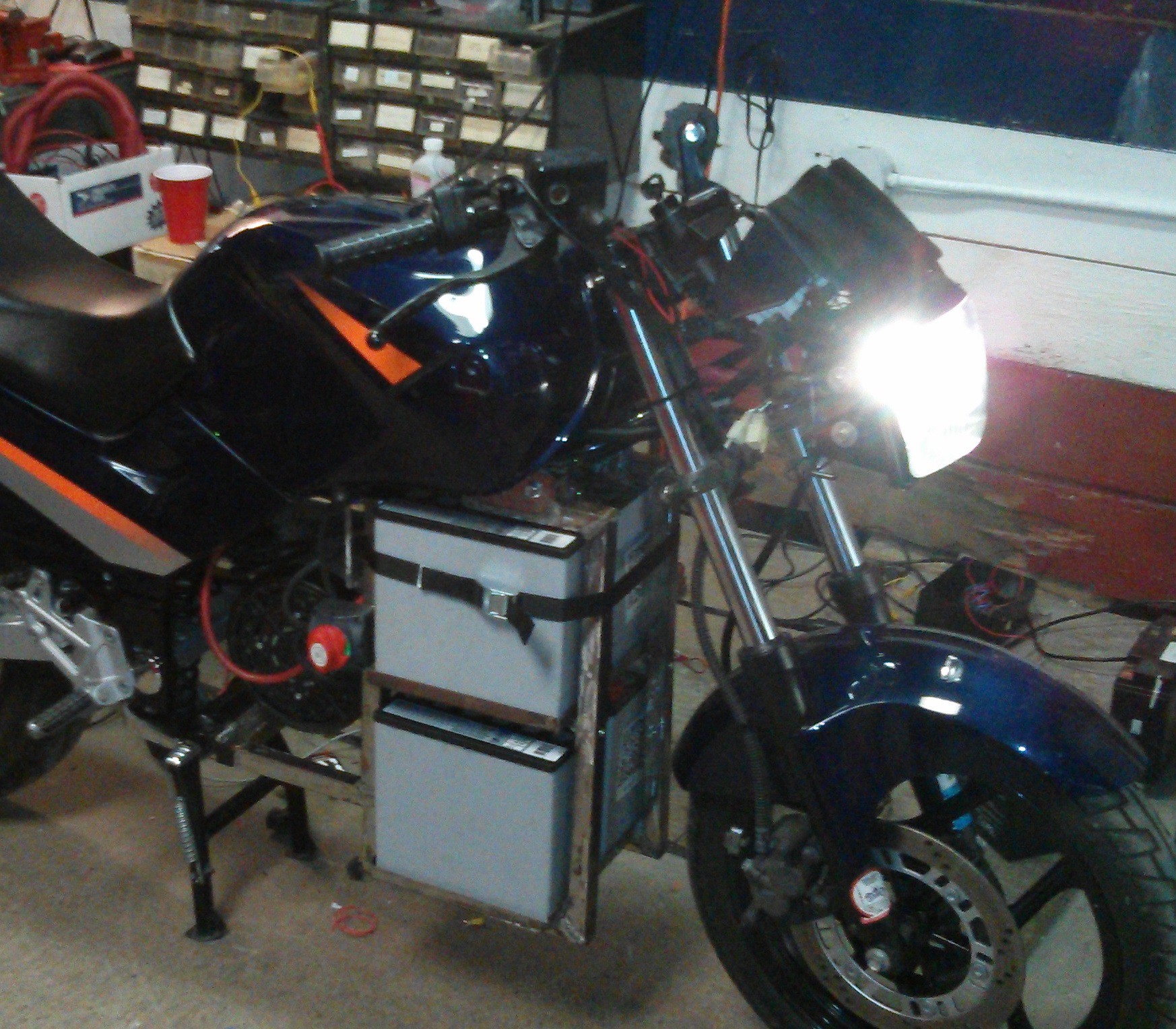
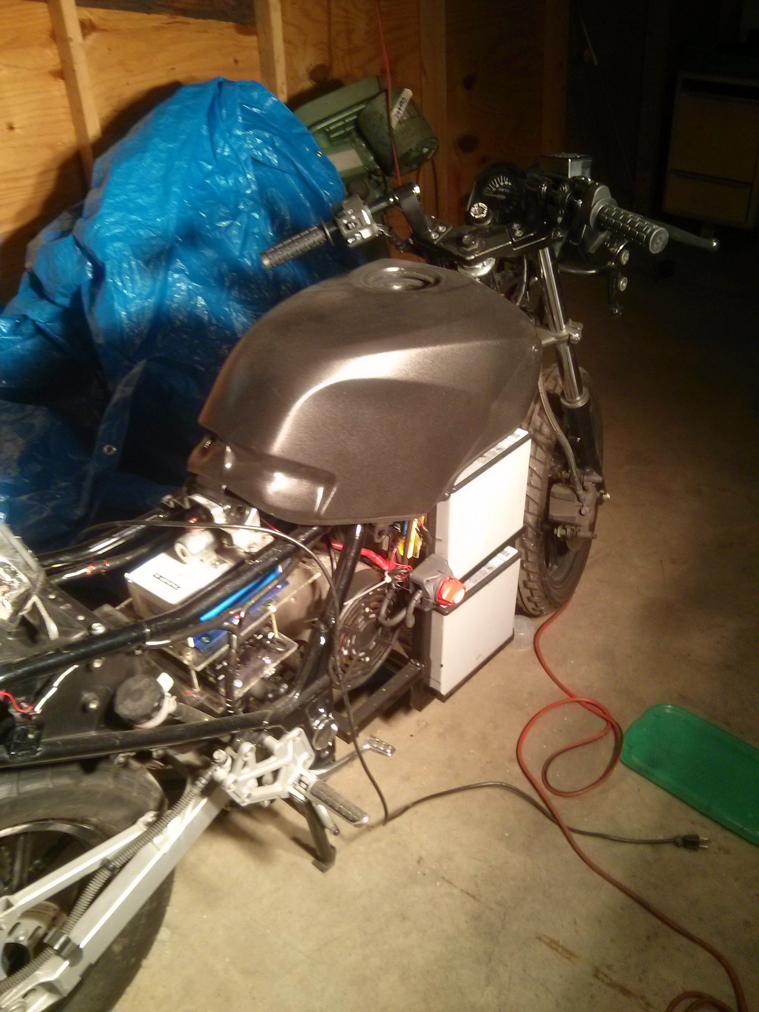
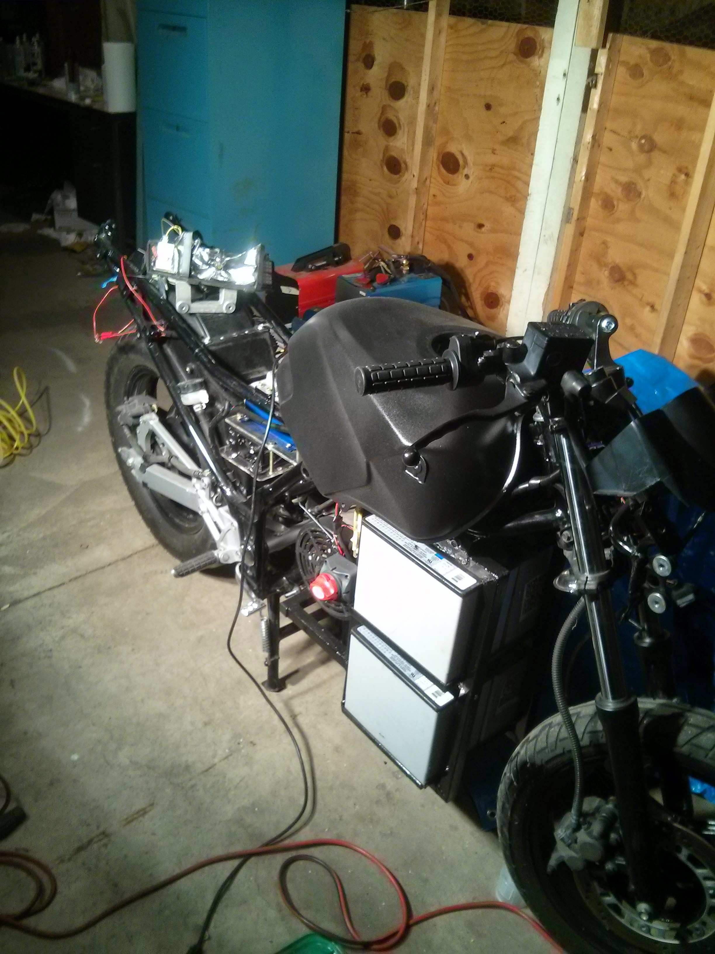
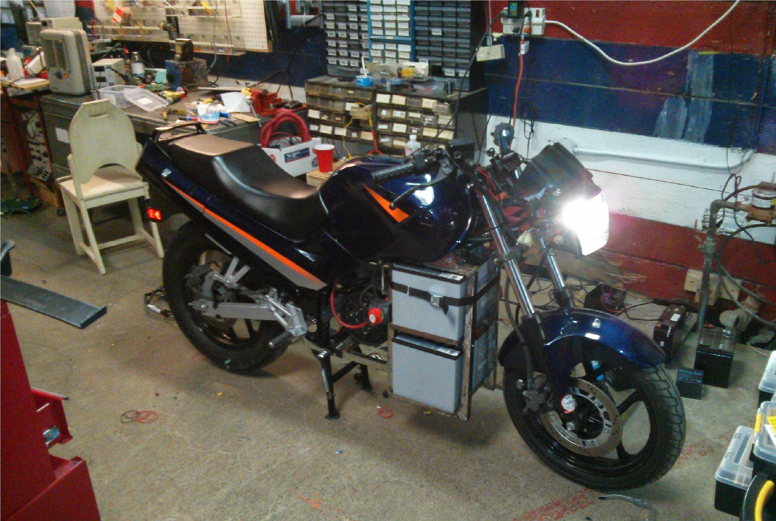
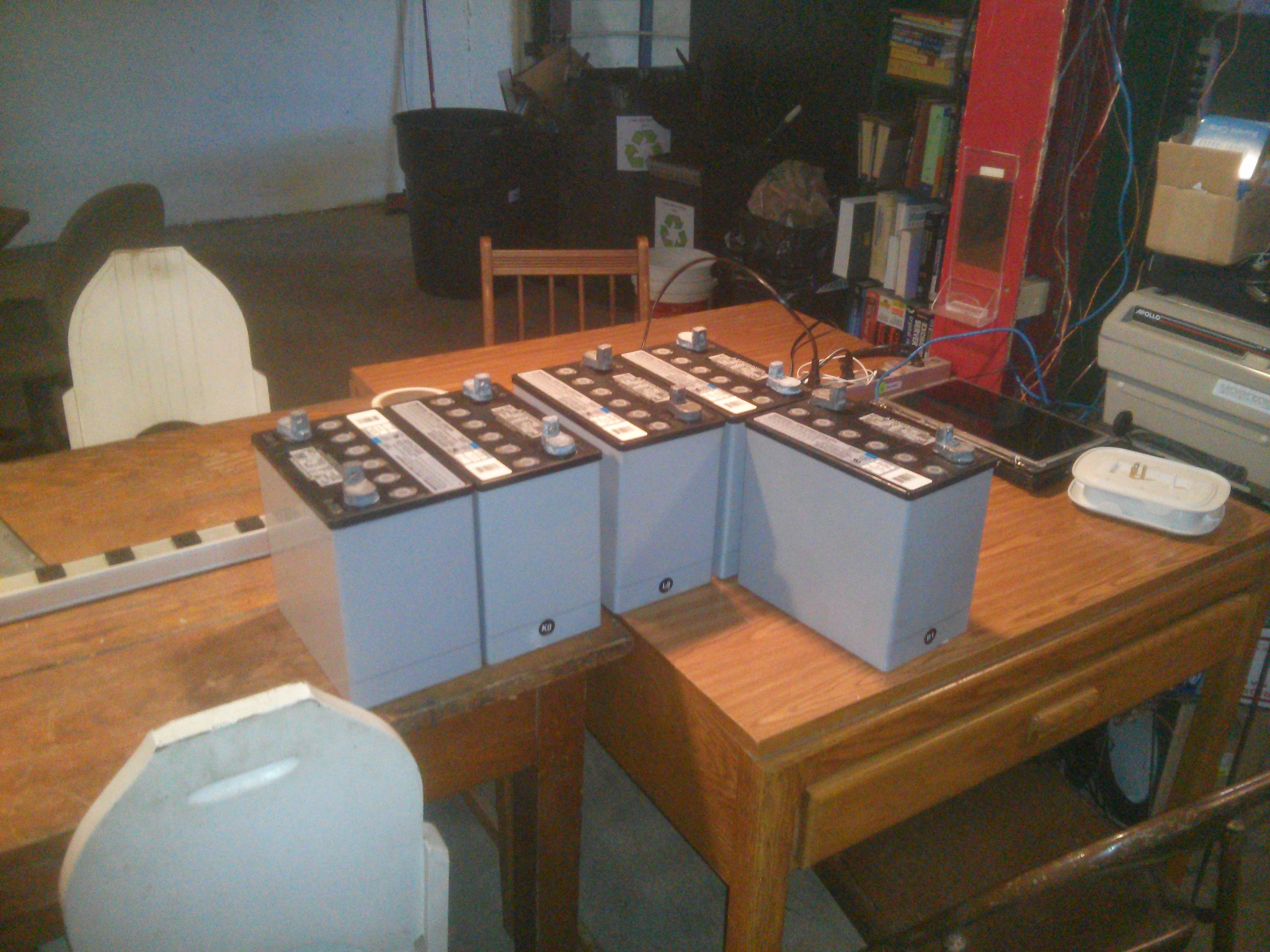
This bike started life as a gas powered machine and is now running purely on electric. The stock engine was replaced with a Mars Etek 48 volt permanent magnet motor. Four 55ah SLA's provide power to the traction system as well as the legacy 12 volt systems and the Arduino.

Status as of 2/15/15:
Most of the mechanical work is done, except for installing a new motor sprocket.
Now my focus turns to the Arduino code to add features and instrumentation.
The instrumentation for current draw and battery SOC is working, I'm still attempting to finish the code for the GRPS modem (bike can text alerts and status info) and the GPS geofencing so the bike will send SMS messages if it moves without being switched on (IE stolen)

These are compiled from questions that people have asked me at events and makerspace open houses where my bike has been part of a display.

FAQ:

  • Is this a hybrid? No, it's purely electric, a hybrid would require having some sort of internal combustion engine still on-board.
  • What's the range and top speed? I don't know, I started this project in late summer and haven't had a chance to take it for a proper test ride (excluding doing laps in the makerspace parking lot).
  • Why did you use lead acid batteries? I used lead acid batteries because they are cheap and take a lot of abuse, unlike fussy chemistries like Li-ion. I also don't immediately need the range of more expensive Li-ion batteries, I plan on using this as a purely inter-city vehicle. That being said I am working on a drop in replacement (physically) that will be Li-ion based.
  • What would you recommend to someone that wants to build an electric vehicle? Just do it, it's so rewarding and it doesn't need to be nearly as complicated as you might think, not to say that can't be, but you can choose your level of complexity based on your skill set.
  • Was it hard to get insured, registered, inspected? Insured no, it's listed as a kit bike by my insurance carrier. Registered, no the NYS DMV was more worried about making sure I paid sales tax than about any mods I've made to the drive train. Inspection, not sure about this one yet, as far as I can determine by reading the state and federal inspection guidelines I am complying with all safety regulations (most of these concern lights).
  • How long does it take to charge? About 6 hours from completely dead.
  • Why don't you add a sidecar full of batteries to the bike so it can go further? Ugh, ok let's tackle this one. First of all batteries add weight and weight reduces range and at some point it's a law of diminishing returns. Two; a side car on a Ninja????? Really? Third, listen I'm already riding an electric motorcycle that I made myself, I would like to occasionally show my face in public again.

  • How could you tear apart a perfectly working Ninja and do this? Ummmm... so I don't know about where you live, but in upstate NY you can't throw a rock in the spring/summer without hitting two Ninjas and someone pining for a flat in the city.

  • 1 × 2005 Kawasaki Ninja 250r
  • 1 × Motenergy ME0810 4.8KW permanent magnet motor Audio Products / Audible Alarms and Sirens
  • 1 × Arduino UNO
  • 1 × SeeedStudio GPRS modem
  • 1 × Adafruit Ultimate GPS

View all 10 components

  • Well this didn't take long

    ErikL08/19/2015 at 17:08 2 comments

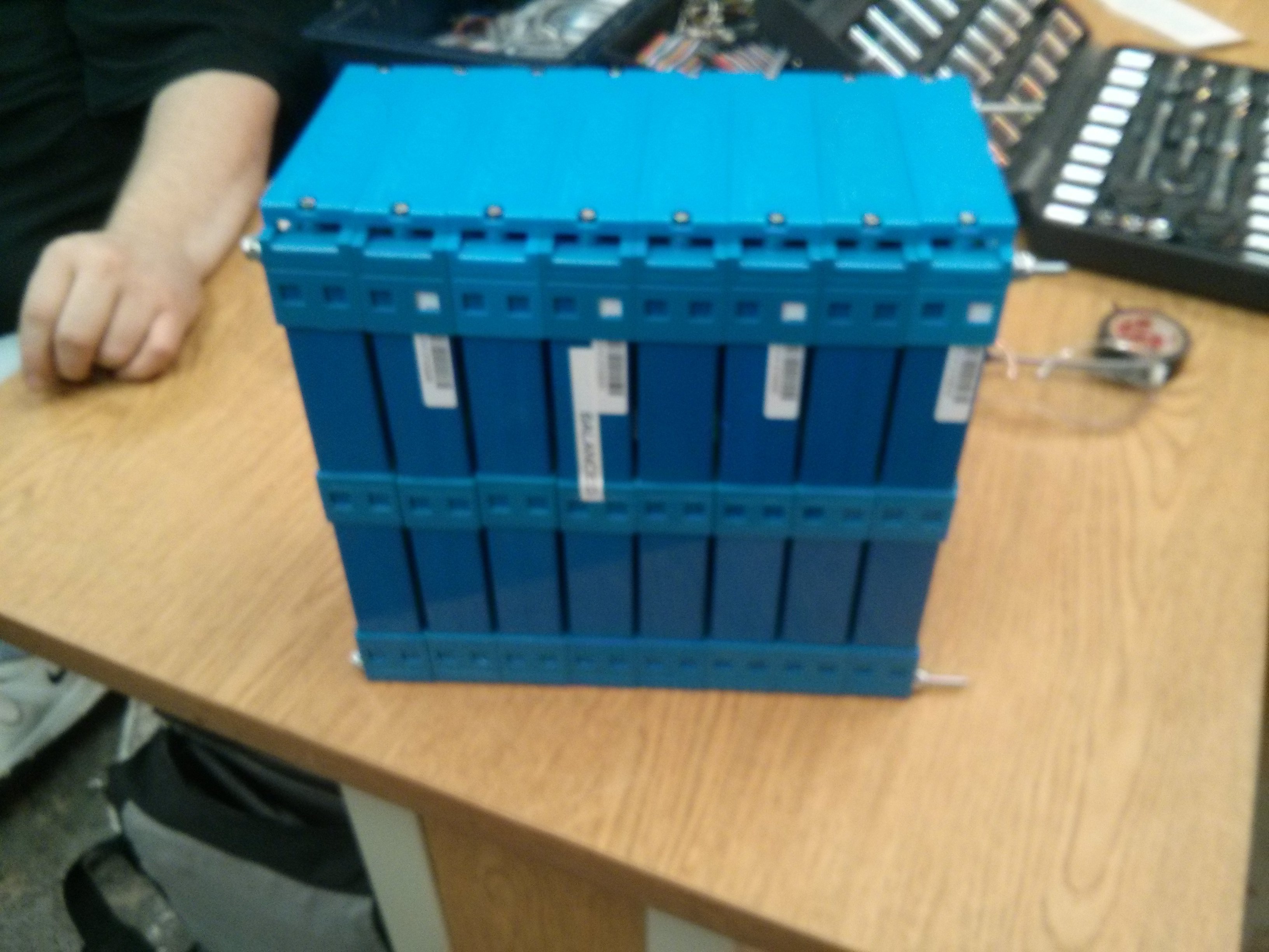
    I thought that it would take me a while to get sick of the lead acid batteries but I was sorely mistaken, so I decided to take the plunge and go for lithium cells. After a lot of research and comparisons I decided to go with the 72Ah CALB LiFePO4 cells. These sells combine an admirable power to weigh ratio and are well documented. The runner up was the Nissan Leaf cells but as they have very little solid documentation and since this is my first time with large lithium packs I would like something that comes with a data sheet.

    The packs consist of two bunches of eight cells each.

  • Maiden voyage

    ErikL05/24/2015 at 14:08 0 comments

    Took the bike for it's first real ride with a destination in mind, which of course was to the makerspace.

    The ride was amazing and magical and I had entirely too much fun. I was happy with how the bike performed, and almost ever aspect of the ride. One thing that I did note and that I'm going to try and remedy ASAP is the straps for the bottom battery tray. The bottom batteries are held in by gravity and a retaining lip around them, but the do tend to jump and jostle on potholes, it's not a big issue but it is disconcerting and is something I'd like to get rid of. I'm hoping that by adding a side bar like I did on the top batteries I can avoid this.

    With the makerspace move wrapping up, and our grand opening approching I'm hoping to have enough spare time soon to be able to focus on getting the instrumentation package installed and working.

  • And then there were updates

    ErikL05/18/2015 at 12:36 0 comments

    Wow, so long time since an update. That's mostly been due to the fact that I've been trying to get the local makerspace set up and moved. Anyway, updates.

    The fairings have cured all the way and been put back on.

    This picture doesn't show the other front fairing installed, but it has since been installed.

    Also the other milestone is that I took the motorcycle out on public roads for the first time. The ride was amazing, and eerie (with the silence).

  • Battery Brackets

    ErikL04/02/2015 at 13:04 0 comments

    While I'm waiting for the paint to cure on the fairings I decided to take care of a few other nagging issues with the bike. Last night that manifested as me building and then attempting to build battery brackets.

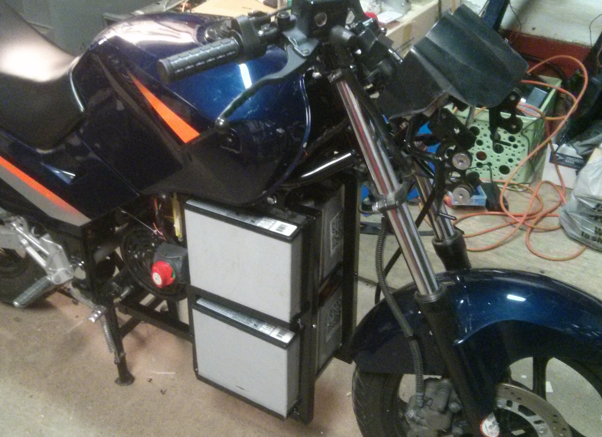
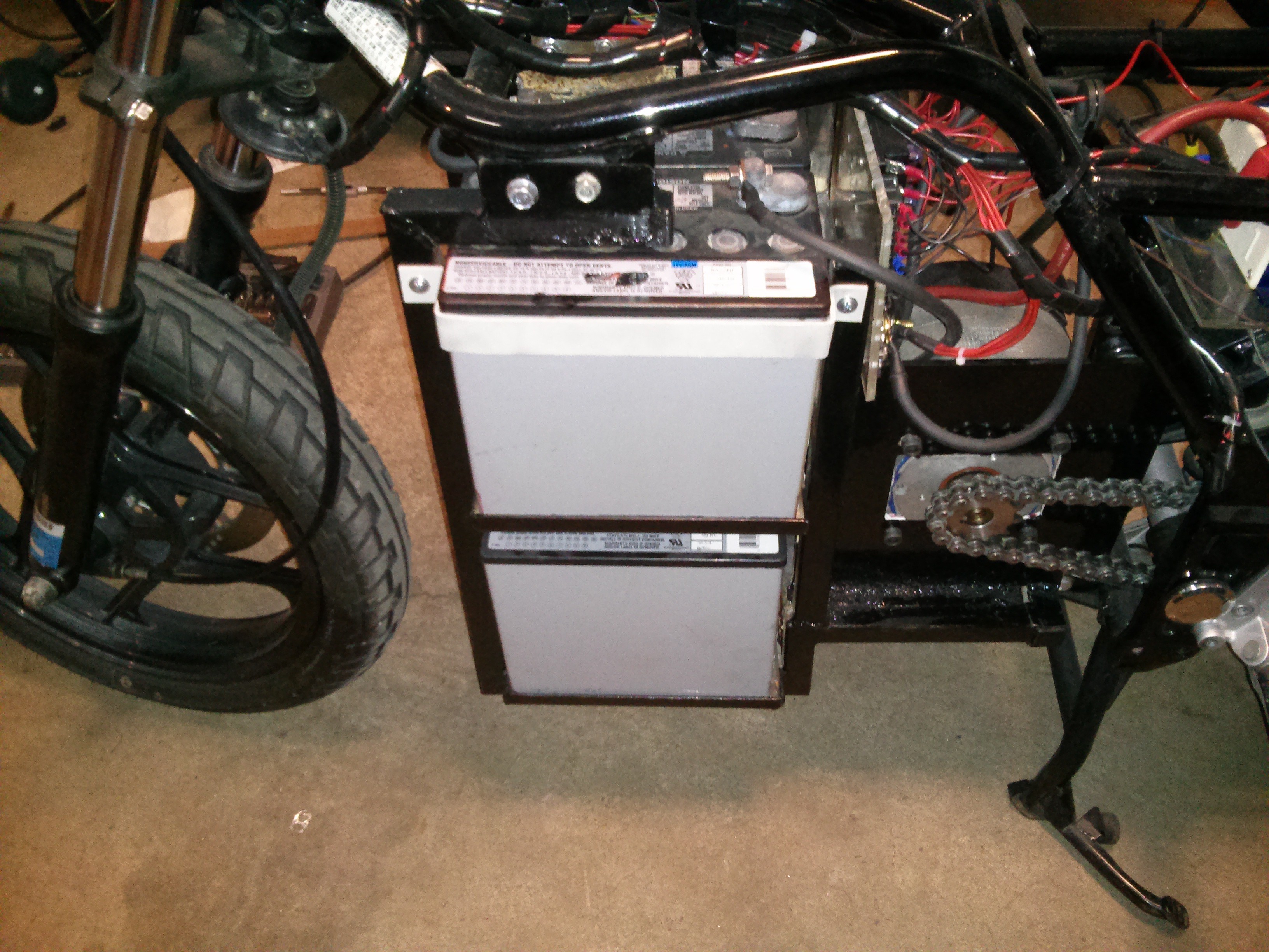
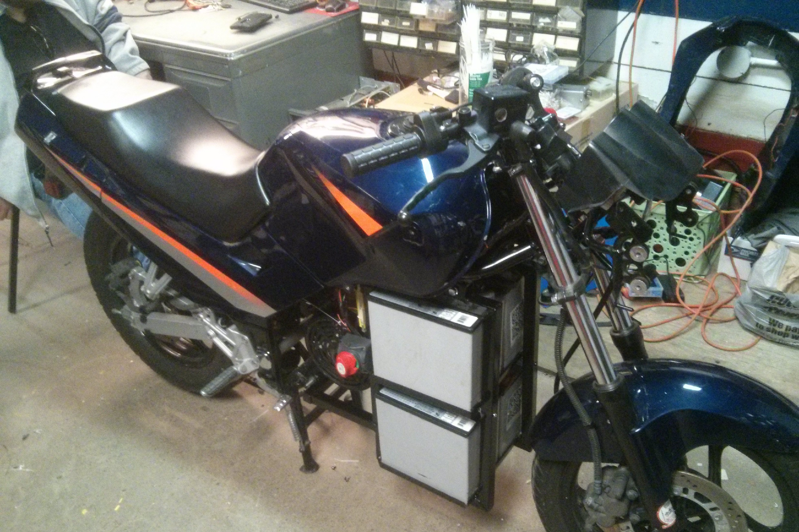
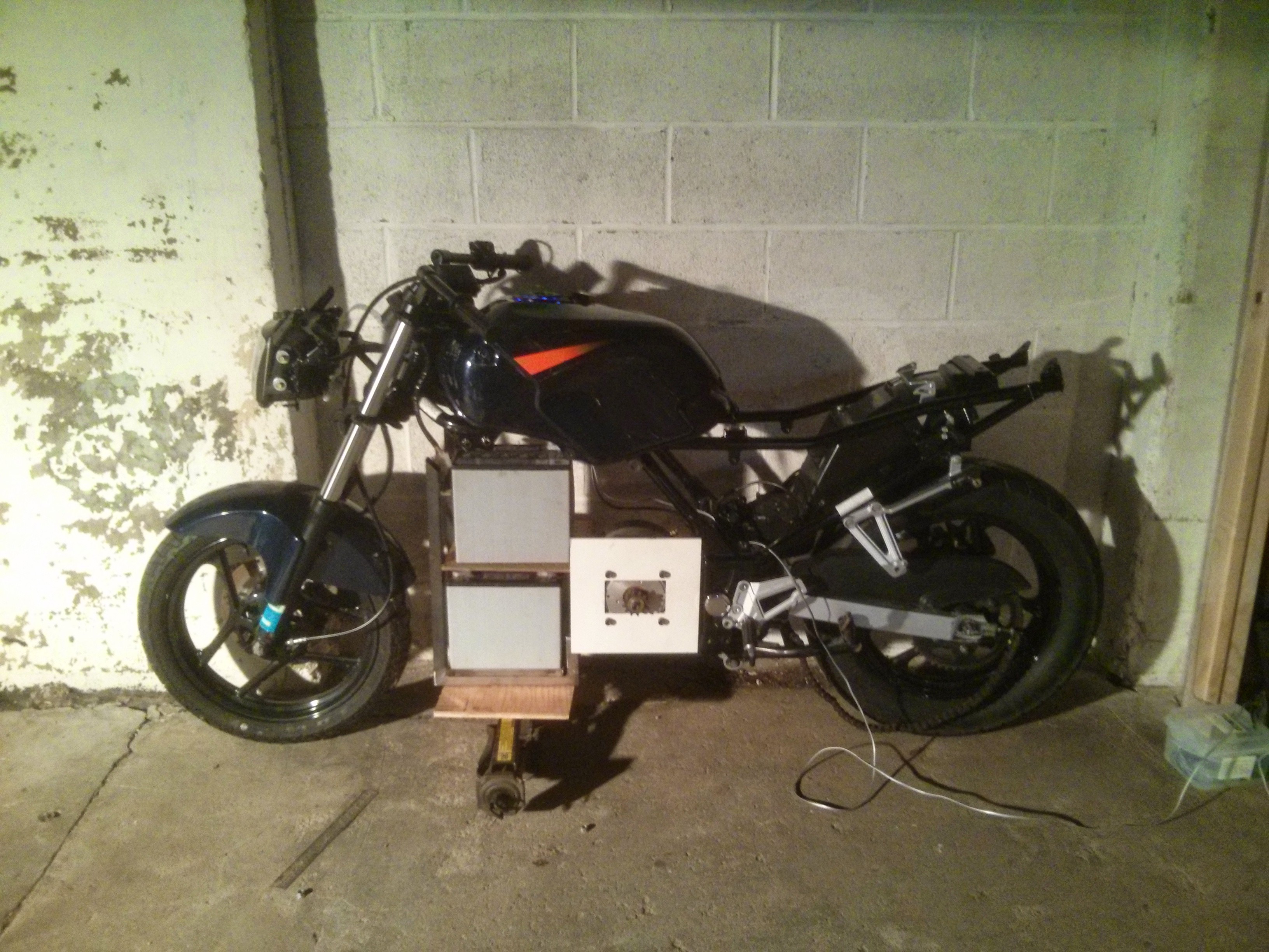
    At present the batteries sit in tray on the frame of the bike as seen in the picture below.

    This design keeps the batteries in when the bike is upright, but if the bike is leaning or falls over, there is a chance that the batteries could shift and short out against the frame, which would be bad. In the past I used a pair of small nylon ratchet straps to hold the batteries stable.

    But the more I looked at this solution the more I didn't like it. The strap had to go all the way around the batteries and the frame, it had to loop near the fuse box, and it had a big conductive metal buckle that could potentially shift and cause all sorts of beautiful spark showers. I thought about it a bit and decided the easiest and cheapest way to make a better strap would be to buy some aluminum flat bar, bend it, tap a couple holes in the frame, and then bolt them on near the top of the batteries. So that's exactly what I did.

    I bent the bars, and then used some 3/4" adhesive foam weather strips to snug them up to the batteries without a sharp edge jabbing into them. Please keep in mind that I bent these bars in a bench vise, as the makerspace doesn't currently have a brake.

    A quick trip though the sandblasting cabinet removed a lot of the tooling sins on the brackets.

    Now you might be saying, OK that's great but why aren't the bottom batteries bracketed in? Good question! So it turns out that the quality of the aluminum at big box home improvement stores varies wildly between each piece. So while the first piece of bar stock I bought bent fine, the other two that I bought just snapped when I tried to bend them. So at the moment I haven't been able to get a second bar that will bend without breaking.

  • I can paint with all the colors of the wind, and a spray can.

    ErikL04/01/2015 at 14:18 0 comments

    With the mechanic portion of the bike project nearing it's end, and the electrical part under way I decided that there was no better time than the preset to start painting. As it turns out painting is a quick and easy process, but prep work and curing times are time eaters.

    The gas tank and front fairing were pretty beat up, so I took extra time to bondo and repair these before painting. Sadly I was lax with picture taking during this part as my hands were covered with glue and bondo.

    I initially started painting in the basement of my apartment, but my roommates weren't thrilled with the paint smell, so I had to move operations to the makerspace. Now while I love the makerspace, in the winter it sucks for painting. Since it's a large industrial space, and we don't have a Scrooge McDuck vault of gold, we keep the space heated but not warm, which is OK for equipment, but not for evaporative chemical processes like spray-painting. To side step this issue I painted the parts at the space with the heaters on at 65, let them sit overnight in the in ambient (45F) temp and then gently moved the parts back to my basement. This way they can cure in the 70F temp of my basement but they're mostly done off-gassing and creating unpleasant smells.

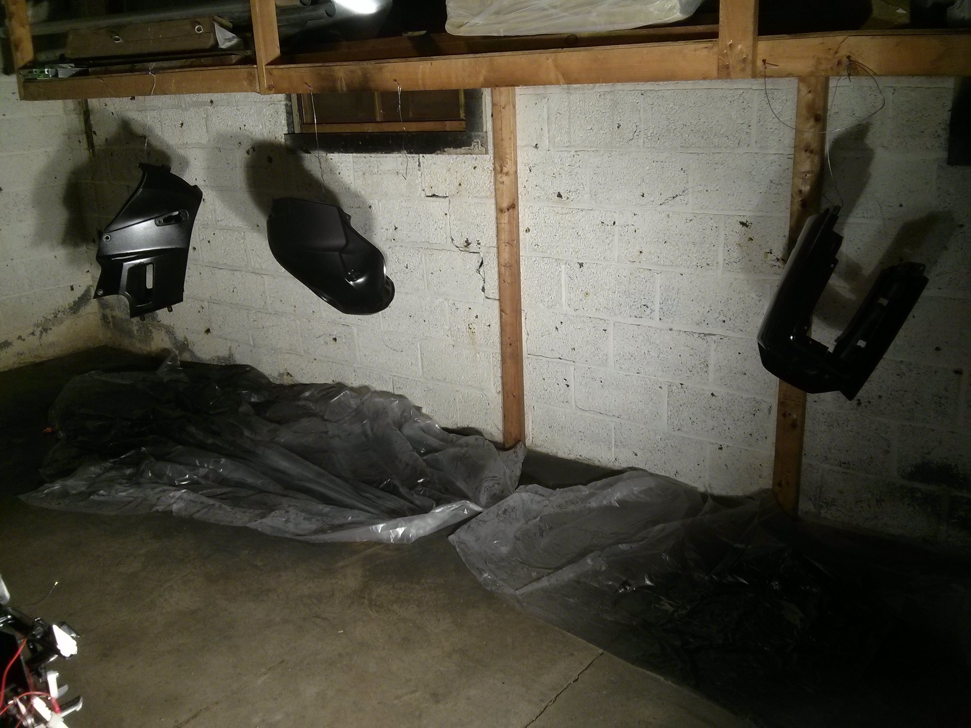
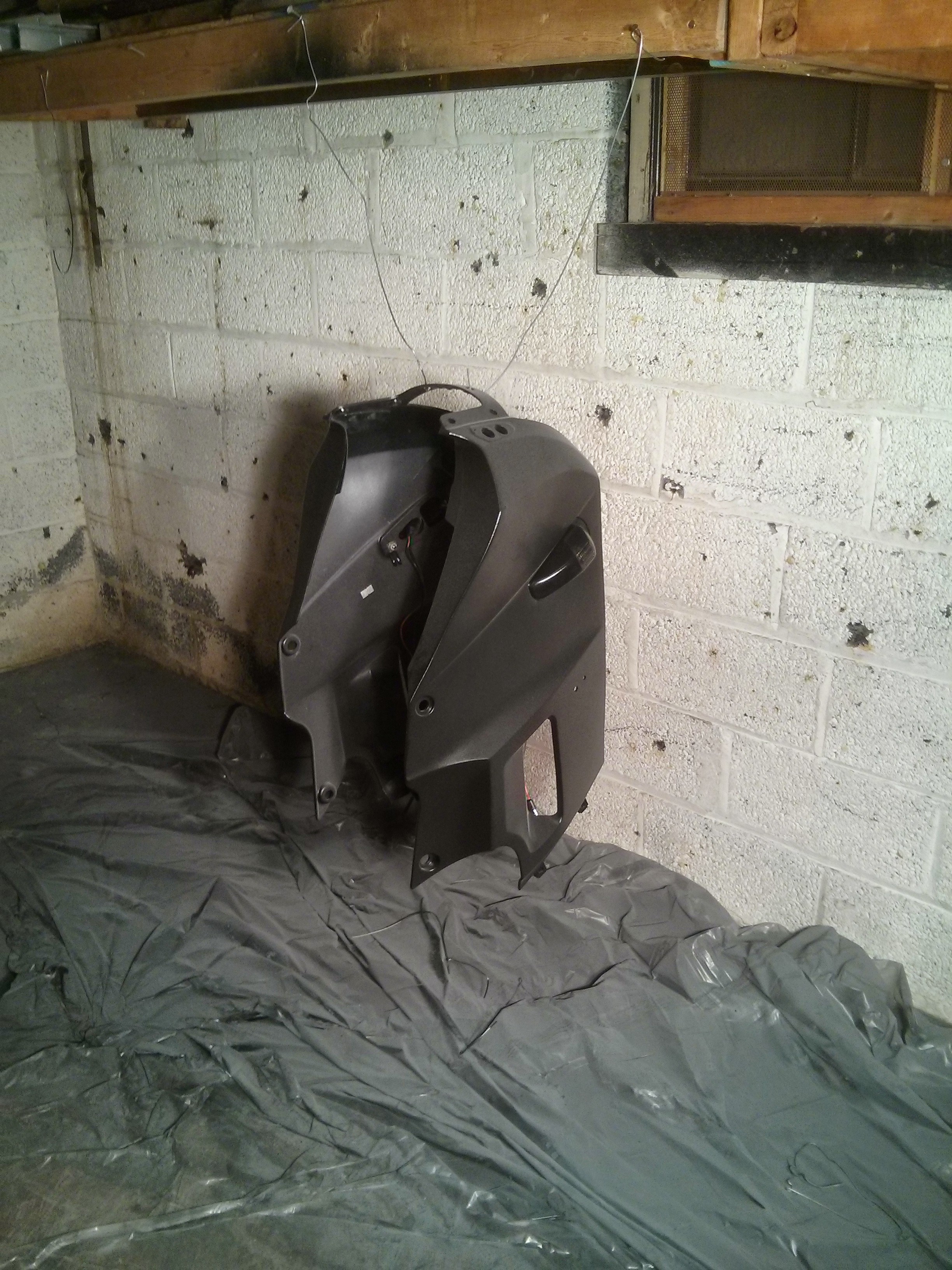
    So I hung the parts up in the back end of the makerspace and went to town.

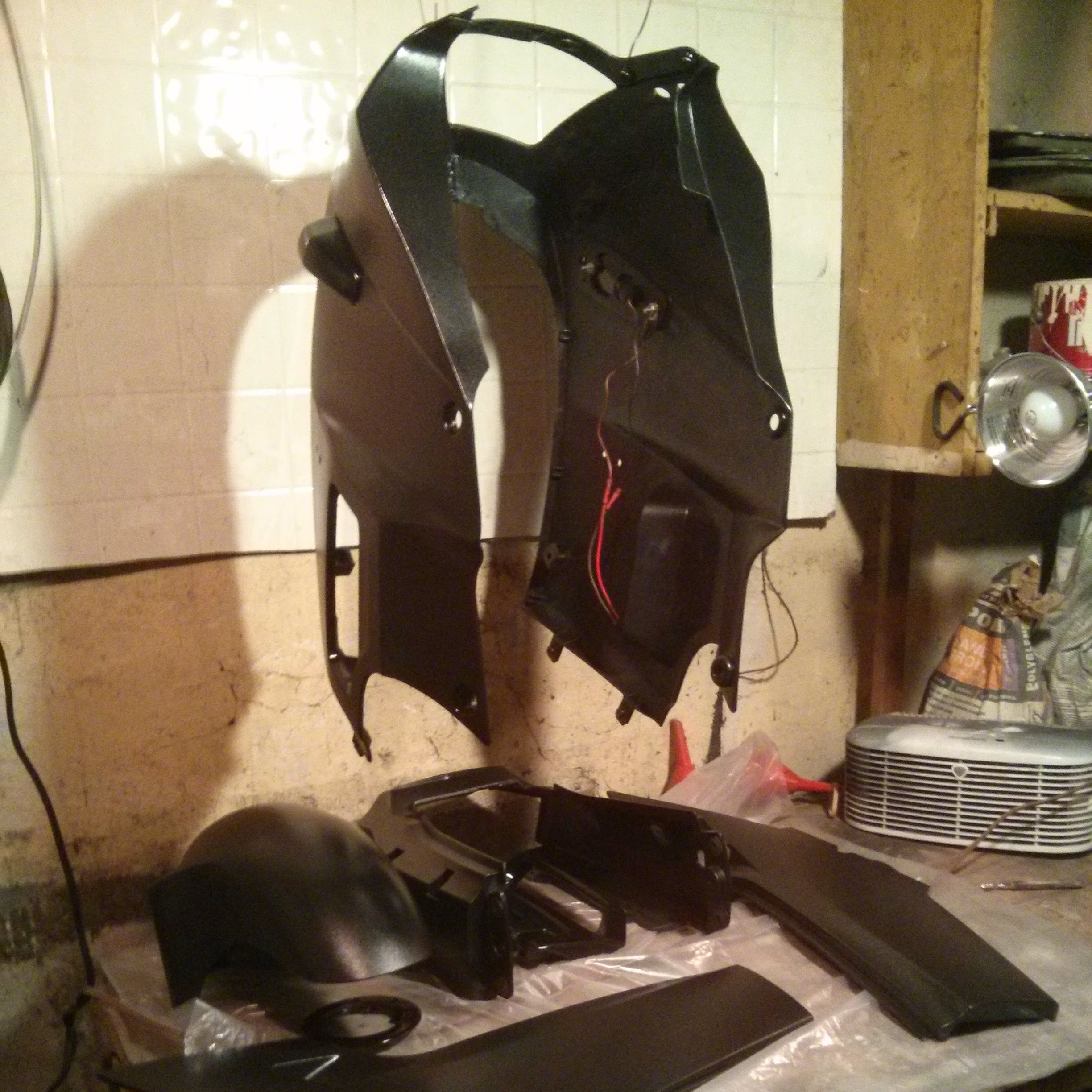
    Thanks to a happy accident and some research I found a paint texture that I fell in love with. When I was painting the first two pieces I accidentally stood to far away from the piece that was being painted. Rather than getting a lovely smooth finish I got a slightly bumpy finish sometimes refereed to as orange peeling. But unlike normal orange peeling this effect was controllable and repeatable, and consisted of a very tight nit closely grouped texture that I can best describe as the slight texturing you see on consumer electronics. It also had a sort of semi-gloss effect, looking slightly flat from a direct angle but shinning from an indirect angle. Comparing two of the pieces that I painted, one that came out buttery smooth and shinny and this micro-textured finish, I loved the micro-texture, it made the fairings look like some sort of ceramic graphine-ish material. Sadly the camera doesn't do it justice.

    The trick was to stand about 2-3 feet away from the part you're painting and then paint like normal, lots of thing coats, give each one a couple minutes between coats, etc. So what was happening here? Why was the paint doing this? After some digging around online I think I found the answer. The paint was starting to dry on it's trip from the can to the surface, and as it was drying it was turning into a little semi-rigid ball. When the paint ball hit the surface it was keeping it's shape and sticking. So by painting in the method and using several thing color coats I was able to build up a textured surface pattern. Hit that surface with clear coat applied from a distance and BOOM!!! the effect was magnified twice over. As a friend described, "It looks like something Batman would make his gear look like. You're like Bruce Wayne on a budget, and with not dead parents"

    Parts hanging up and curing

    A note on curing. When you spray paint something the paint has chemical agents in it to help it dry these chemicals evaporate out of the paint while it's drying, this process usually takes a few hours and is colloquially refereed to as "dry to the touch". At this point the piece can we lightly handled without messing up the paint. But as you may have discovered, or if you're lucky you haven't, the paint isn't up to it's full strength. This is because the paint layers that aren't in direct contact with the air are still soft, think of it like brownies, you've got a harder outer layer surrounding a gooey inner layer, awesome for brownies, sucky for parts that need to be installed and handled. Now if you leave your brownies, or painted parts out, for several days (a week or two is ideal) then this gives the inner layers time to dry too,...

    Read more »

  • Ash to ashes, dust to dust

    ErikL03/11/2015 at 19:51 0 comments

    Last couple days have been a flurry of sanding and painting. I've been painting the fairings on the bike, and trying to hide some small dents that the gas tank suffered in a former life. Learning a lot, like the fact that many thin coats of bondo is better than one big one (it likes to crack).

  • Update 2-23-2015

    ErikL02/24/2015 at 06:22 0 comments

    Painting with all the colors of the wind, combined, and viewed at night. Tonight I gave the metal frame a quick coat of black enamel.

    Before:

    After:

  • Update 2/22/2015

    ErikL02/22/2015 at 23:54 0 comments

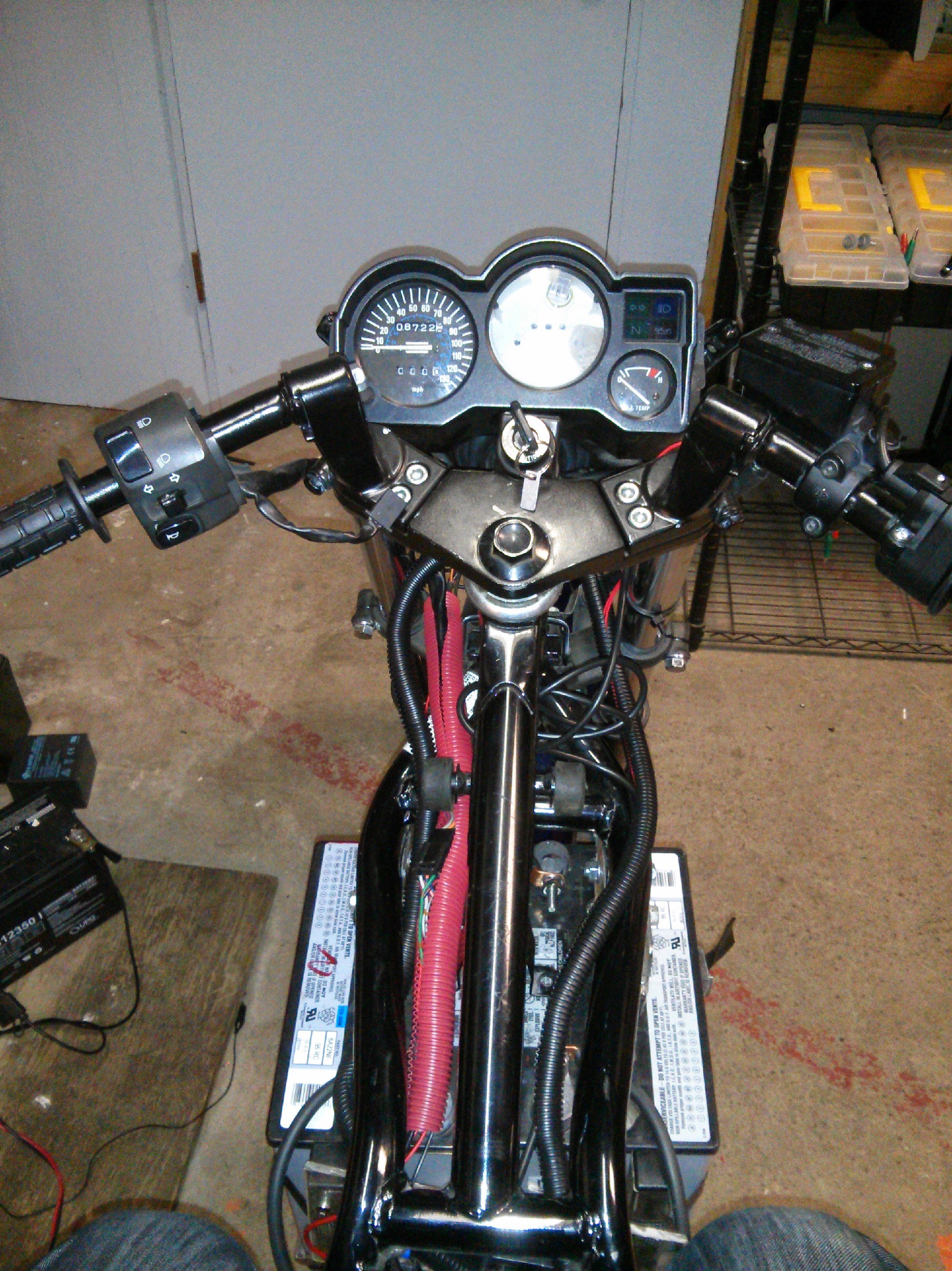
    Coulomb counter installed. I had to cut the crimp off the main power line as with the lug on the wire, it's just slightly to big to fit through the opening on the Hall sensor. I left the board disconnected because I did't have my USB to serial adapter with me and I didn't feel like hunting down drivers for any of the ones at the makerspace.

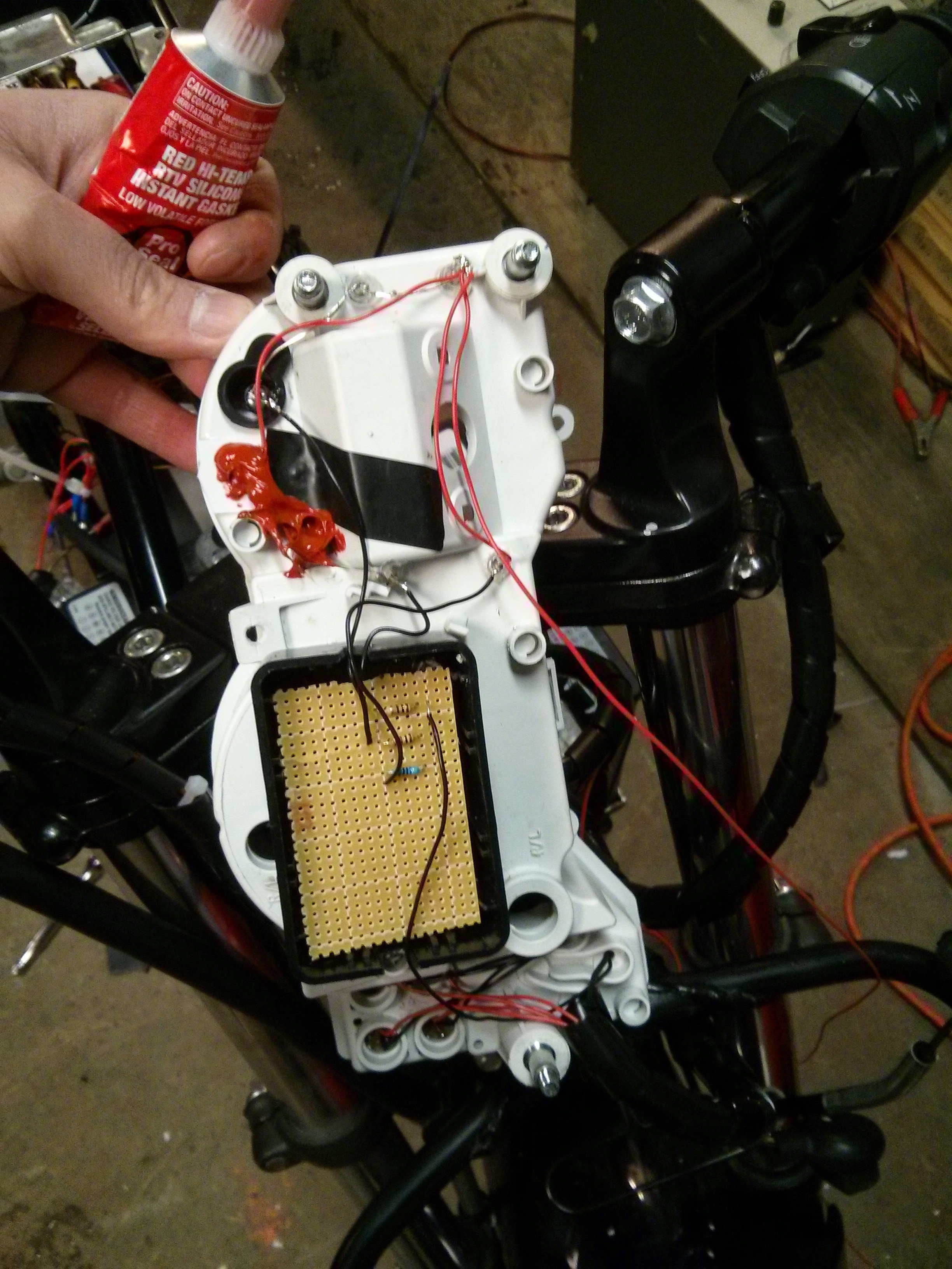
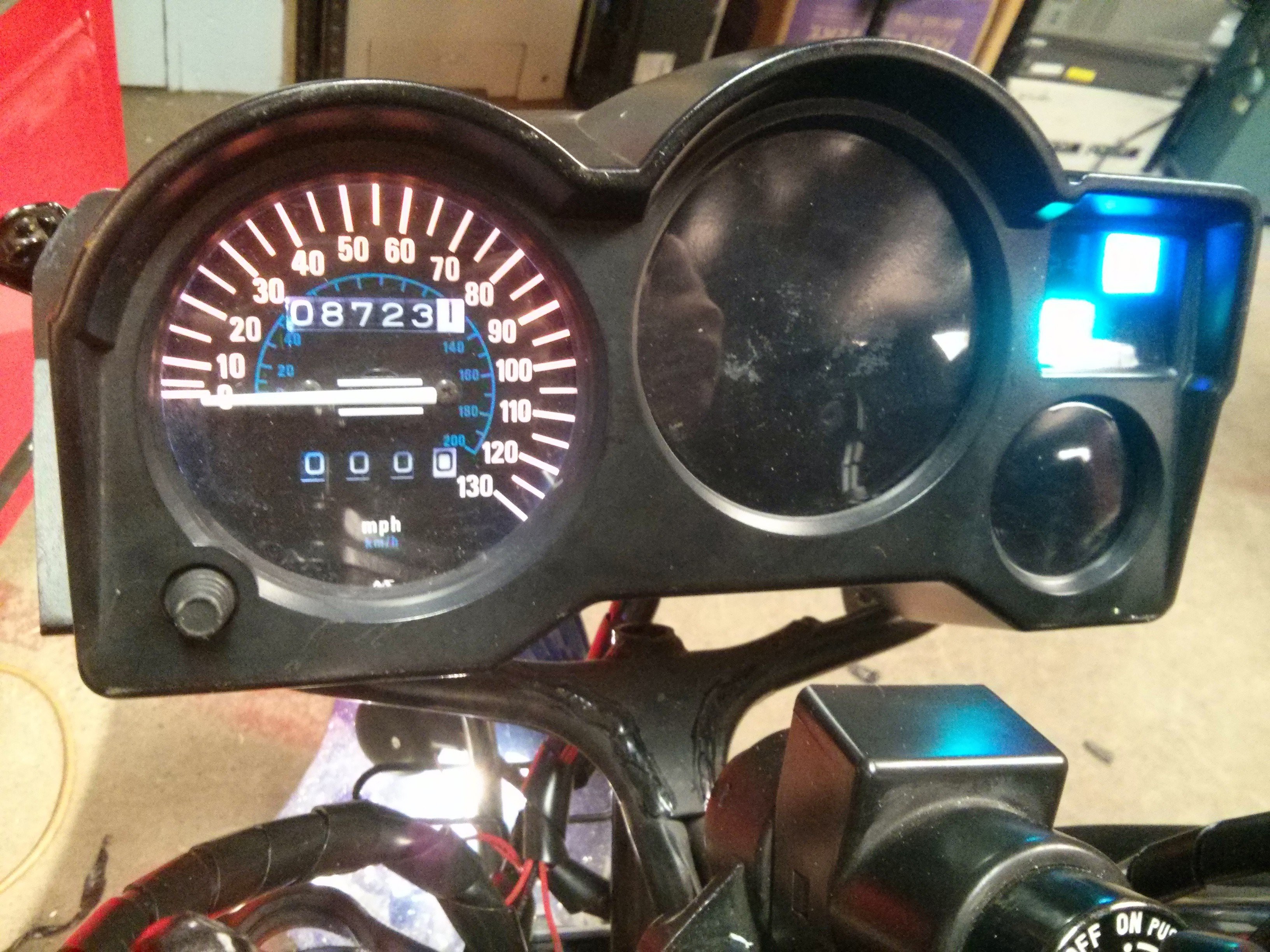
    I also installed an LED backlight for the speedometer. I was shocked how much power the incandescent bulbs in the gauge cluster used, for the 6 bulbs it was over 2 amps. I've since replaced all the indicator lights with small hand made LED arras, and the backlights too, total draw is under 200ma. I used RTV rubber to close up some cable holes in the back of the cluster (there was a wire bundle for the temp gauge and tachometer.

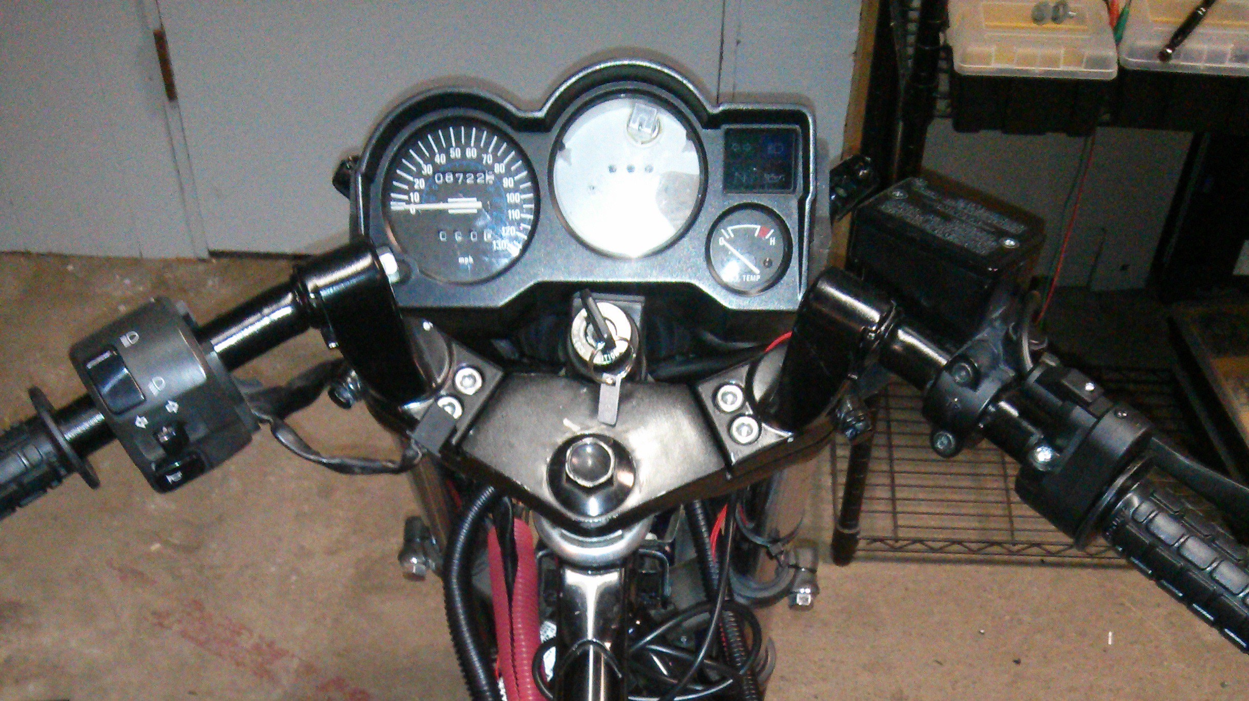
    The cluster is looking a lot less mutilate now that I used some black vinyl to mask off the area where the tachometer and temperature gauges went. I've got a custom neopixel and OLED unit that will be installed the tachometer original was. Until that's ready I wanted to make the cluster look a little nicer.

    Before:

    After:

  • Update 2/21/2015

    ErikL02/22/2015 at 02:34 0 comments

    Long night, but I was able to get the 12 volt power supply working properly. I initially wired it up so that it pulled power off the same connection on the primary contactor that the motor controller used. This ended up being problematic as the 12 PSU would siphon off any charge built up in the caps in the motor controller which did three bad things:

    1. Drained the caps in the motor controller, and also prevented them from being able to pre-charge, this is bad for the controller.

    2. It made the headlight and 12 volt indicators flash on and off as they pulled residual power from the controller, once the key was turned off.

    3. This parasitic load on the power system made the charger never reach a "full charge" state.

    The easy solution to this problem was to use an extra set of switched wires that were on the key-switch to turn on a relay that turns power on to the 12 volt PSU. Key switch off, motor controller can keep is pre-charge because the PSU is disconnected. Key switch on, primary contactor enables power to the motor controller, second switch poles turns on relay and the 12 volt PSU gets power and the headlight and indicators turn on. Turn to position Labeled "Start" on key-switch and for some reason the second pole is disconnected and you enter a mode that I've dubbed "stealth mode", where the motor controller is on but the 12 volt regulator is off, so no indicators or headlight, perfect for sneaking up on people Ninja style.

    I also removed the split loom and replaced it with spiral wire wrapping. This resulted in a night and day difference in the spaghetti factor. I also took the oportunity to cut off a lot of excess cable length, and combine several wires that had individual crimps into single crimp connections.

  • Progress to date

    ErikL02/16/2015 at 14:16 0 comments

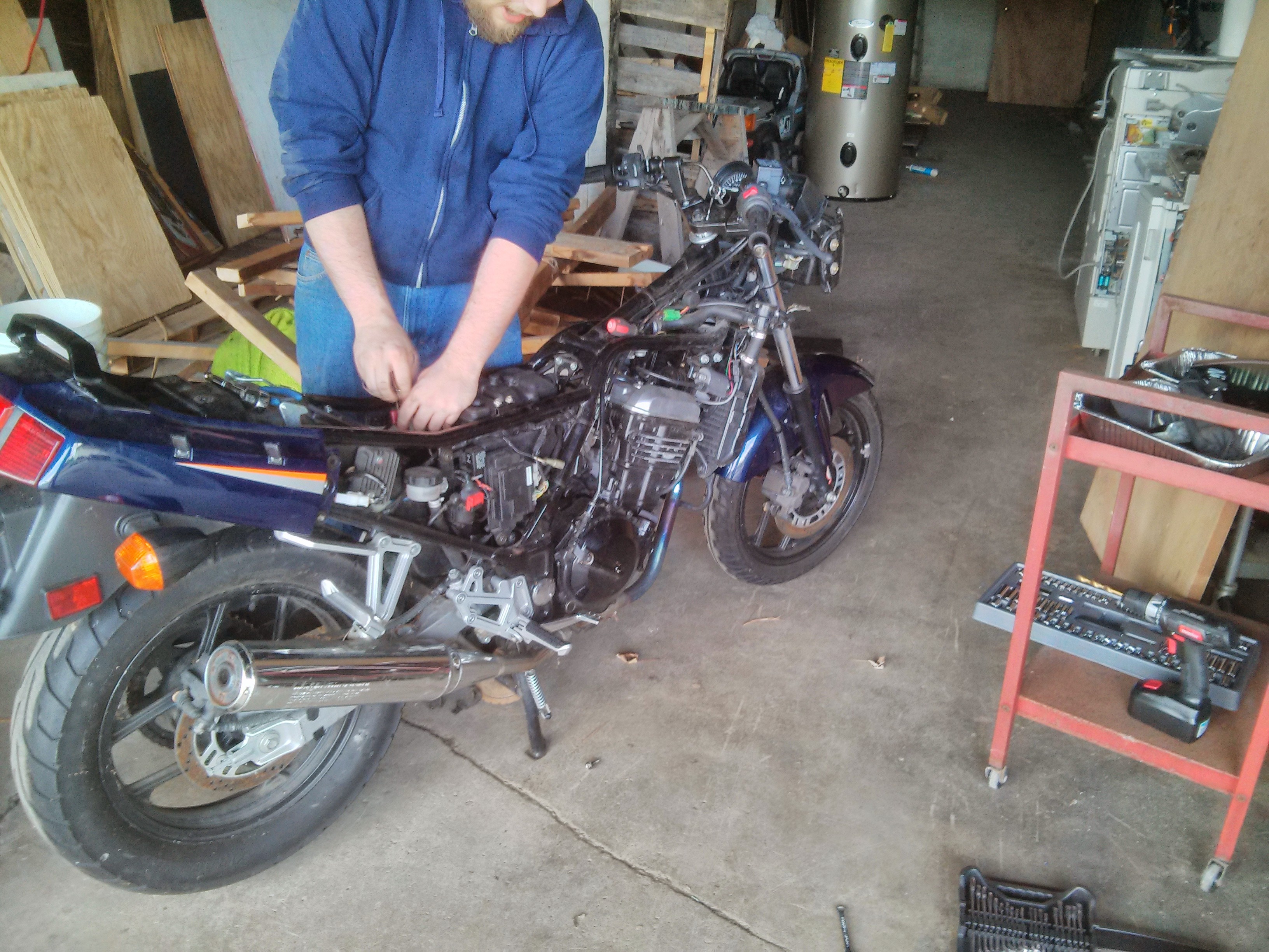
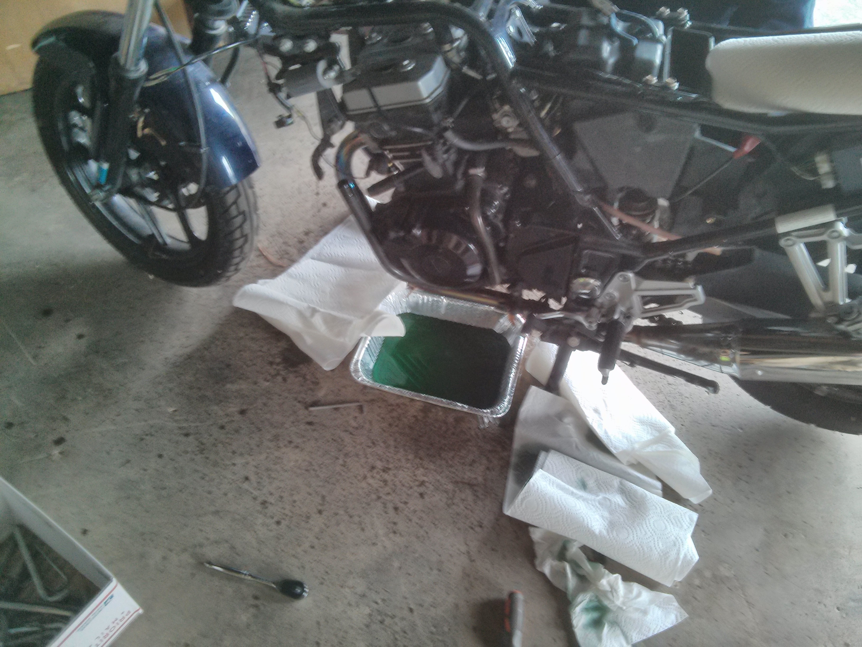
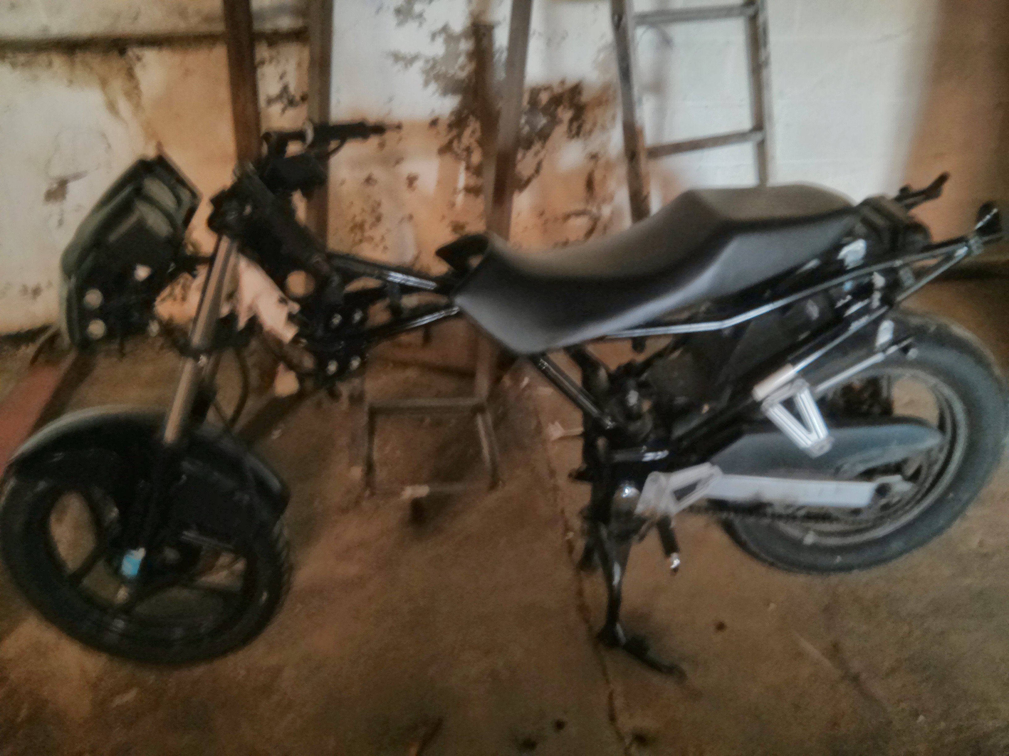
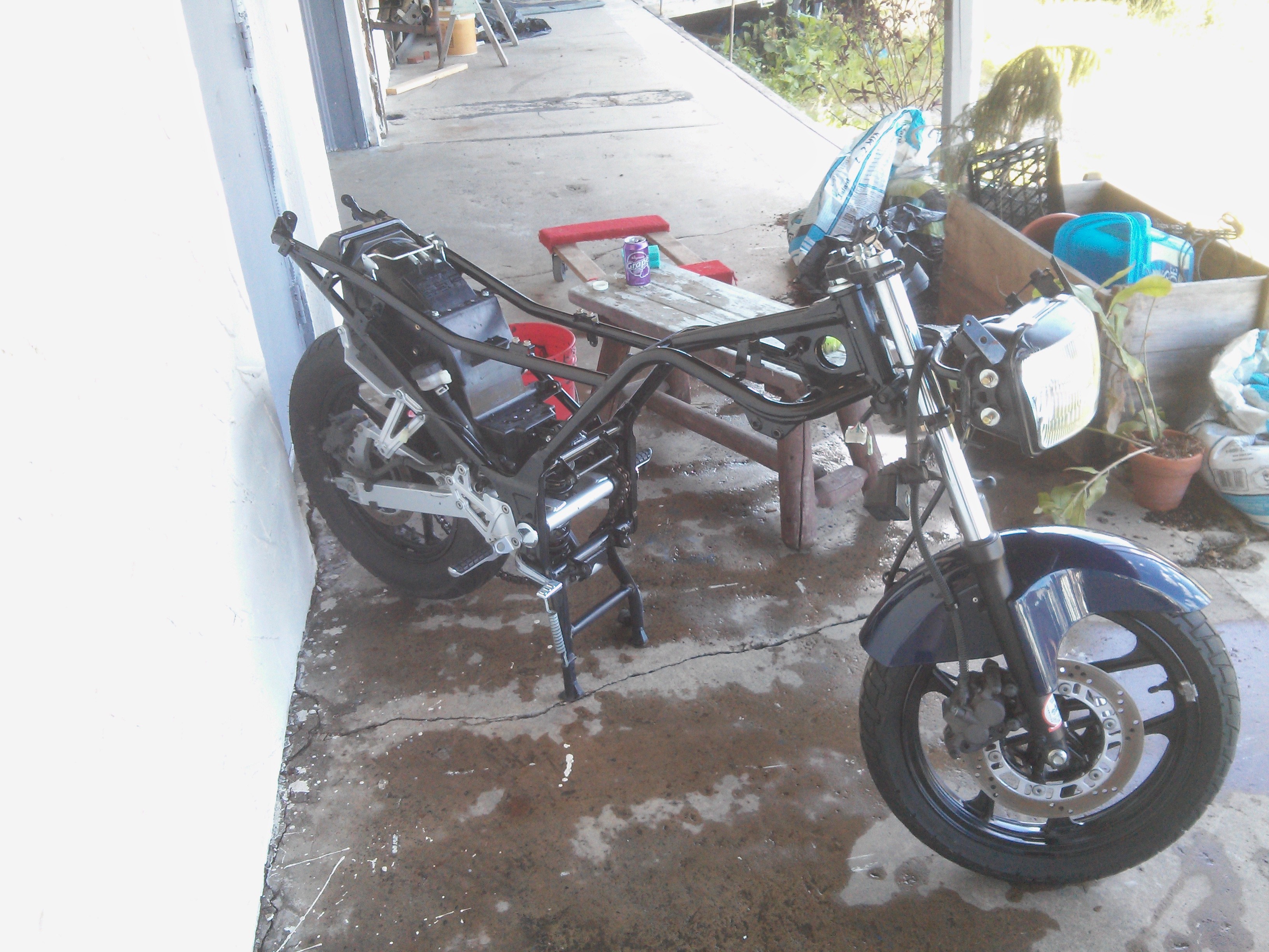
    Project started with removing the internal combustion engine and related components. This took the better part of 2.5 hours. Luckily I had help from a fellow friend and maker, Kevin, on this.

    Started by removing the fairings, and large easy to get to pieces like the air box, exhaust. Then it was time for the gushy parts.

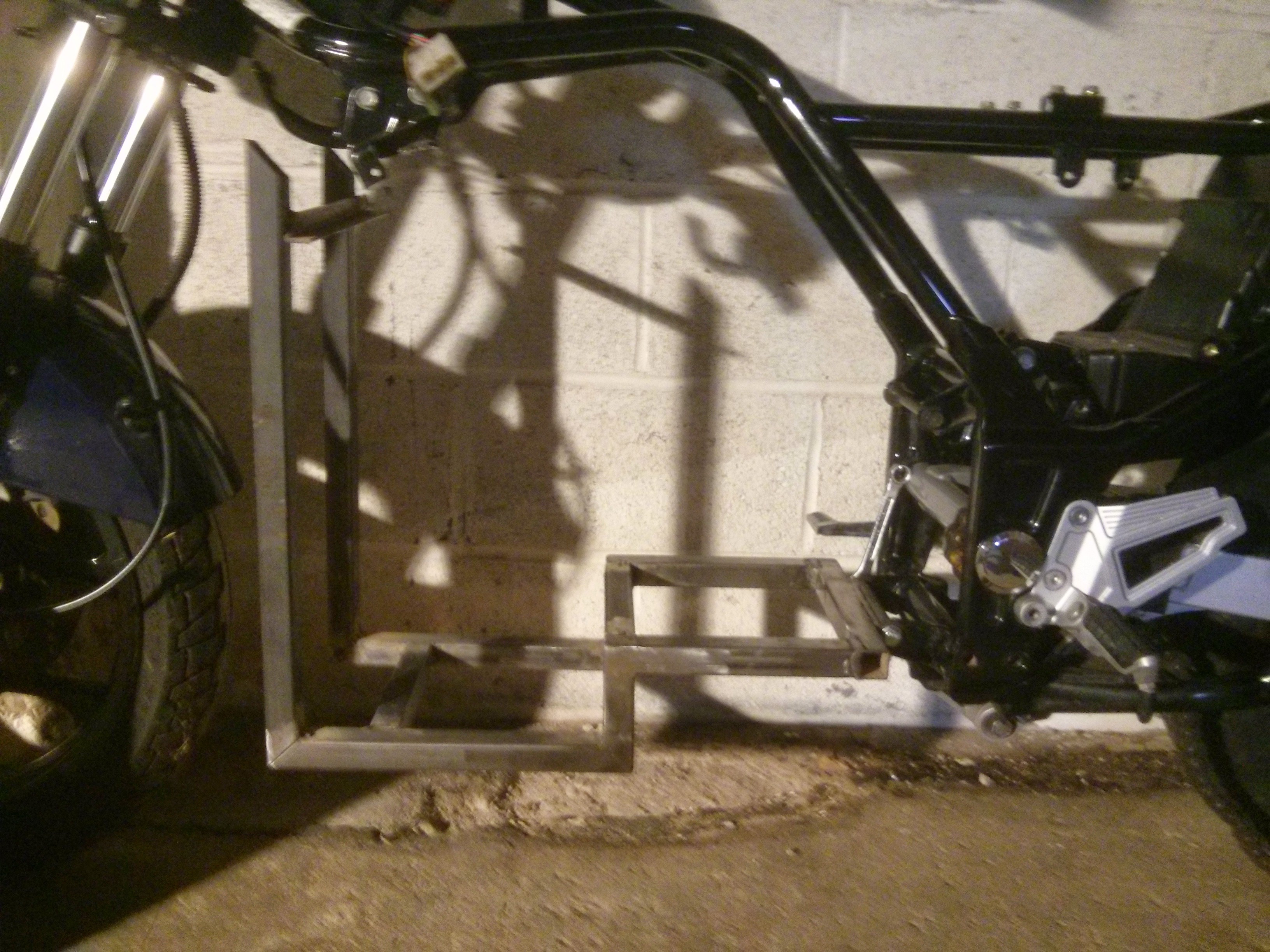
    At this point we tried to make a battery tray that would use the existing hangers from the frame:

    This looked cool, and fit well, but sadly didn't leave enough room for two more batteries and the motor.

    As I didn't have a way to machine a mounting plate, Kevin promised he would have one laser cut for me at his office, ah the perks of having machines that can precisely cut 1/4" steel.

    In the mean time I turned my attention to cleaning the bike, as it had accumulated a lot of grime and gunk from it's years of having a gas engine.

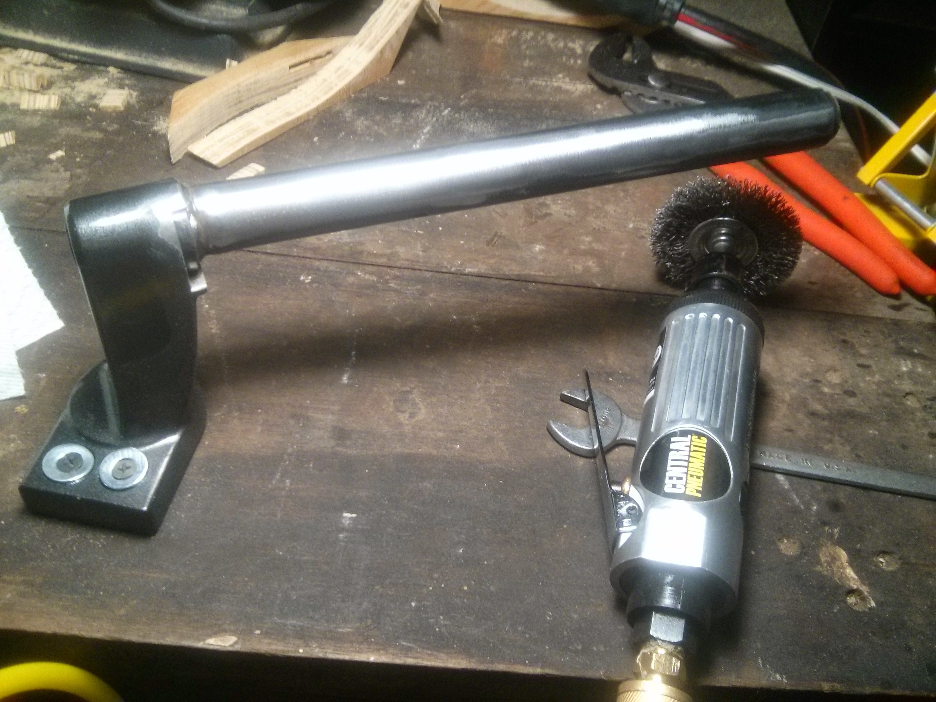
    I also repainted the handlebar assemblies as they had started to flake paint. Wire wheel for steel:

    Sandblaster for aluminum:

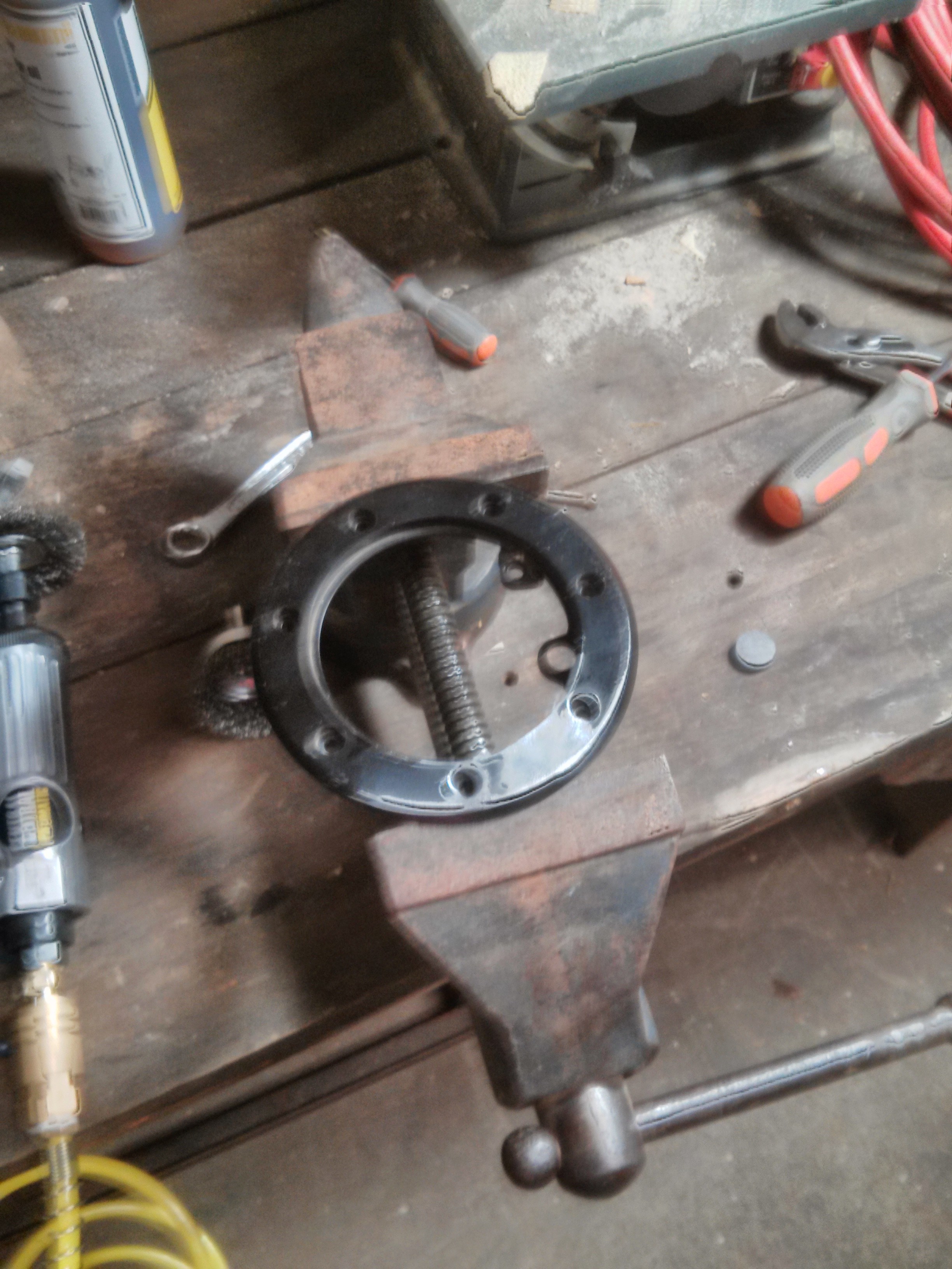
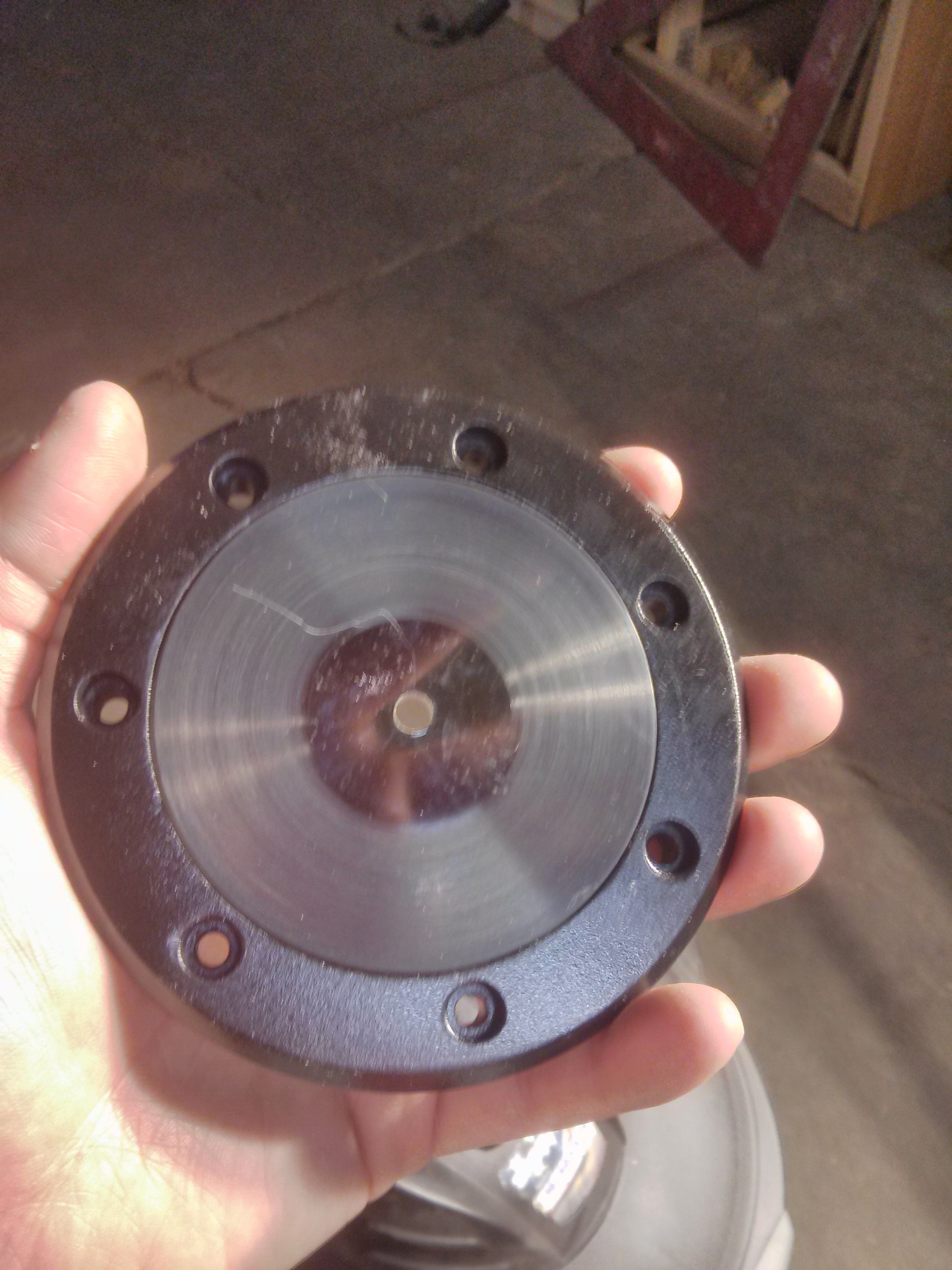
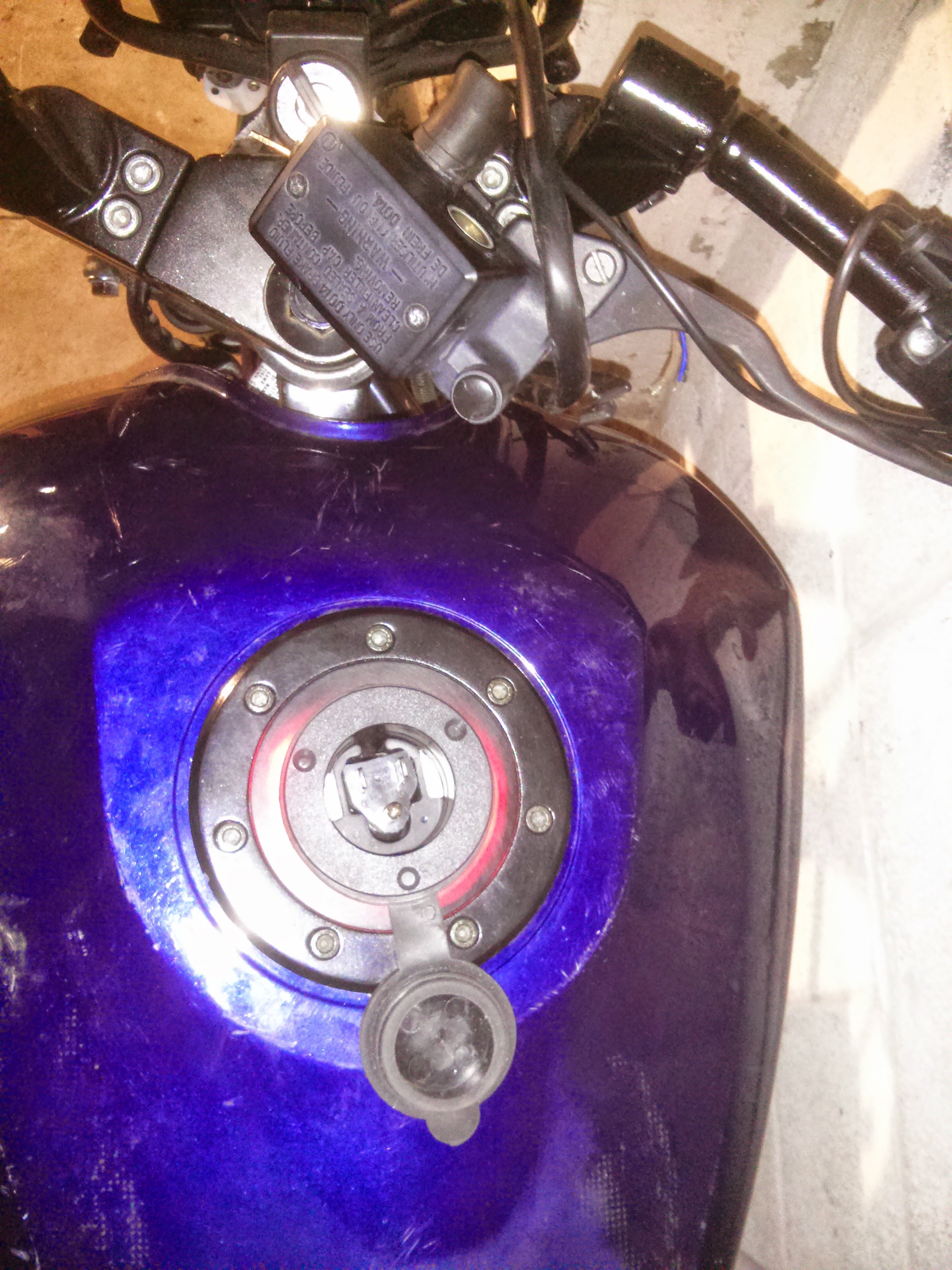
    I had also decided that I wanted the gas tank inlet to be the new charging port. I removed the OEM gas cap which left me with a metal ring with an internal flange the exact depth of 1/4" polycarb.

    So I cut out a disk of smoked poly-carbonate and then sanded the outside dimensions to fit, and used a second hole saw and the original pilot hole to cut out the middle hole.

    After a little sanding and polishing to clean it up, I added a marine AC charge port.

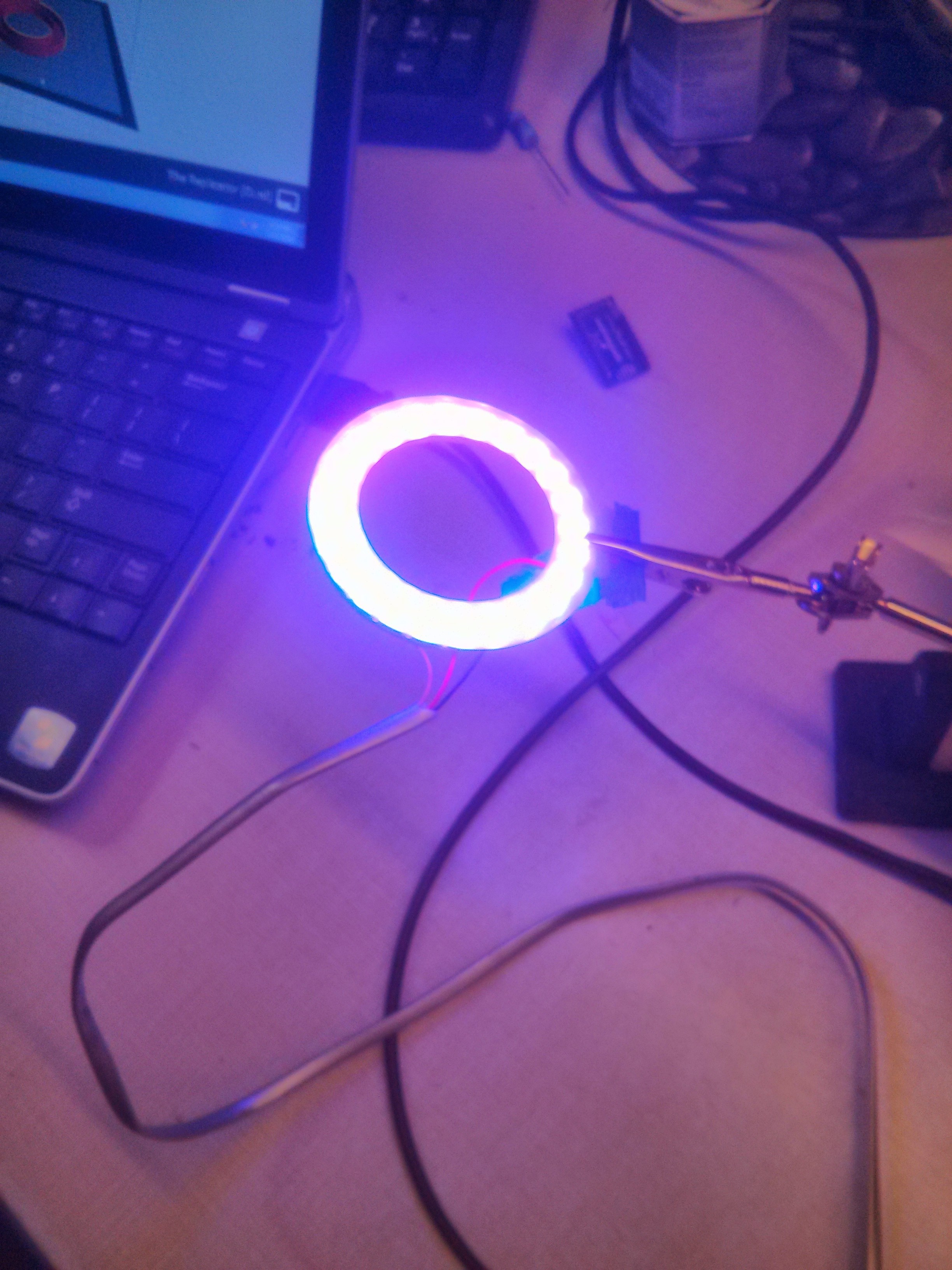
    And what could make this pop more than a ring of Neopixels:

    Installed below:

    The LED's are controlled by an Arduino and reflect charge status.

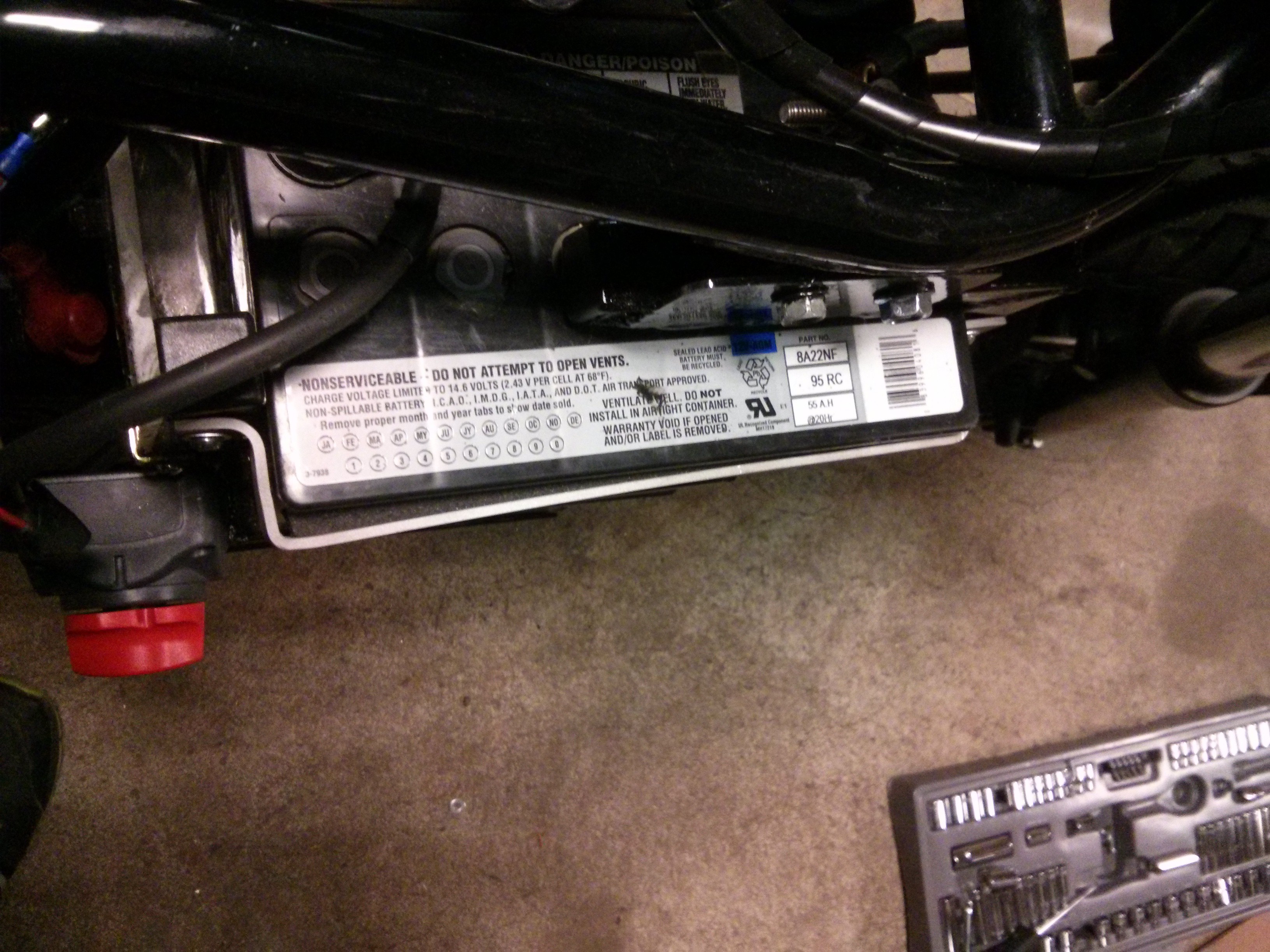
    I had originally intended to use some smaller batteries that I bough new of Amazon, but after doing some more calculations I decided they were to small, and that the makerspace could use them for a Power Racing Series project that was already underway. Luckily I was able to score some used 55ah SLA's of Craigslist for about $50 a piece.

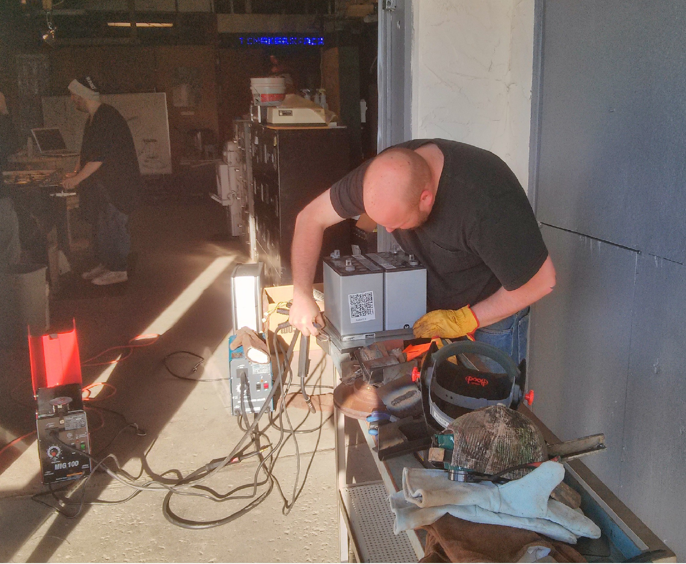
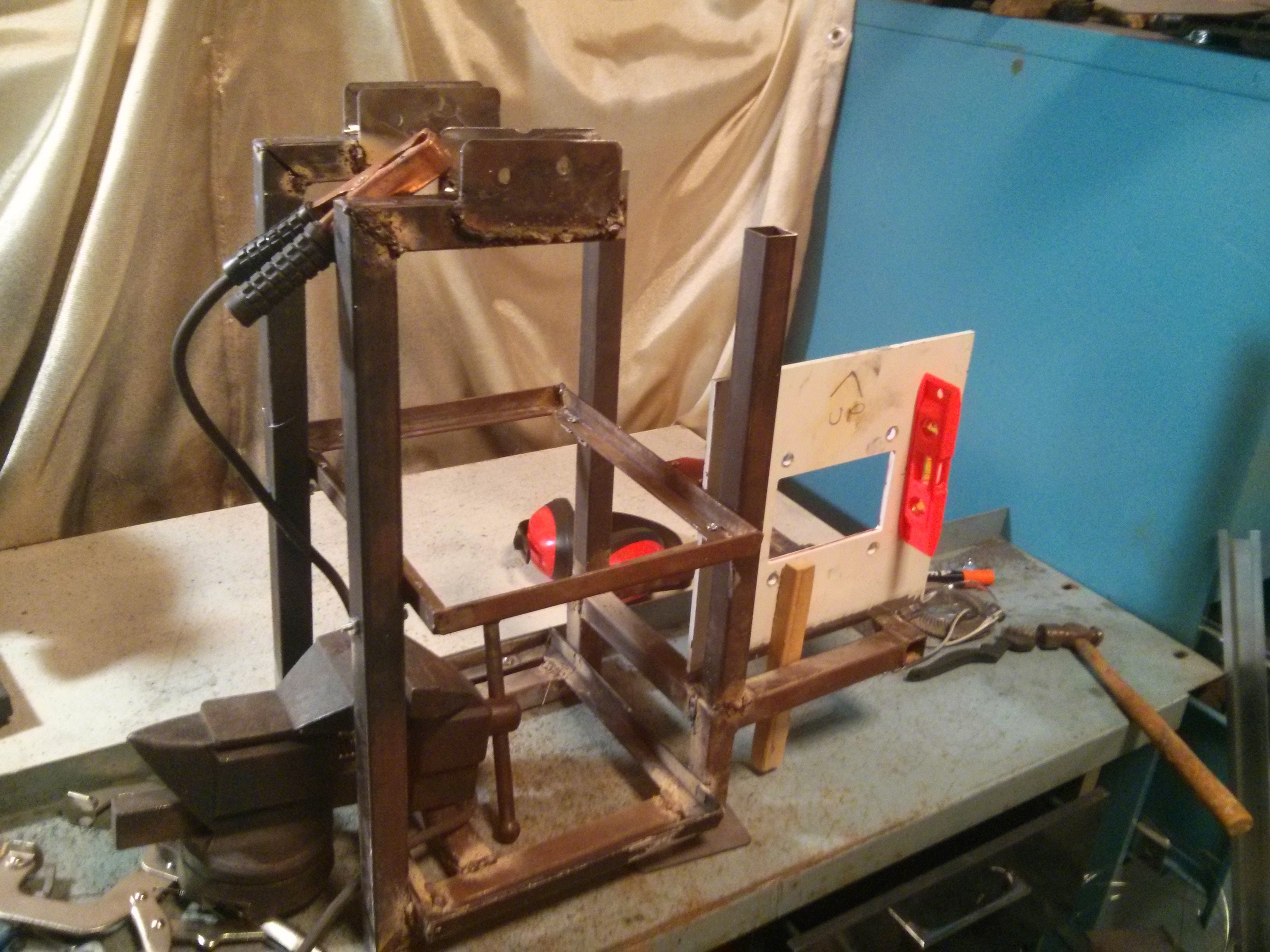
    The frame was built out of 1" square stock, since it's easy to cut and weld and the seams are all long flat lines, which are perfect for beginning welders.

    The frame building process went slow, as I would tack some pieces together and then test fit the batteries and motor. While this was time consuming it did same me from having any "Oh shit" moments.


    After a couple weeks of late nights and lots of test fits, the frame started to take shape. One great advantage to this design is that I have have to make zero changes to the existing frame, this design is literally a bolt in replacement.

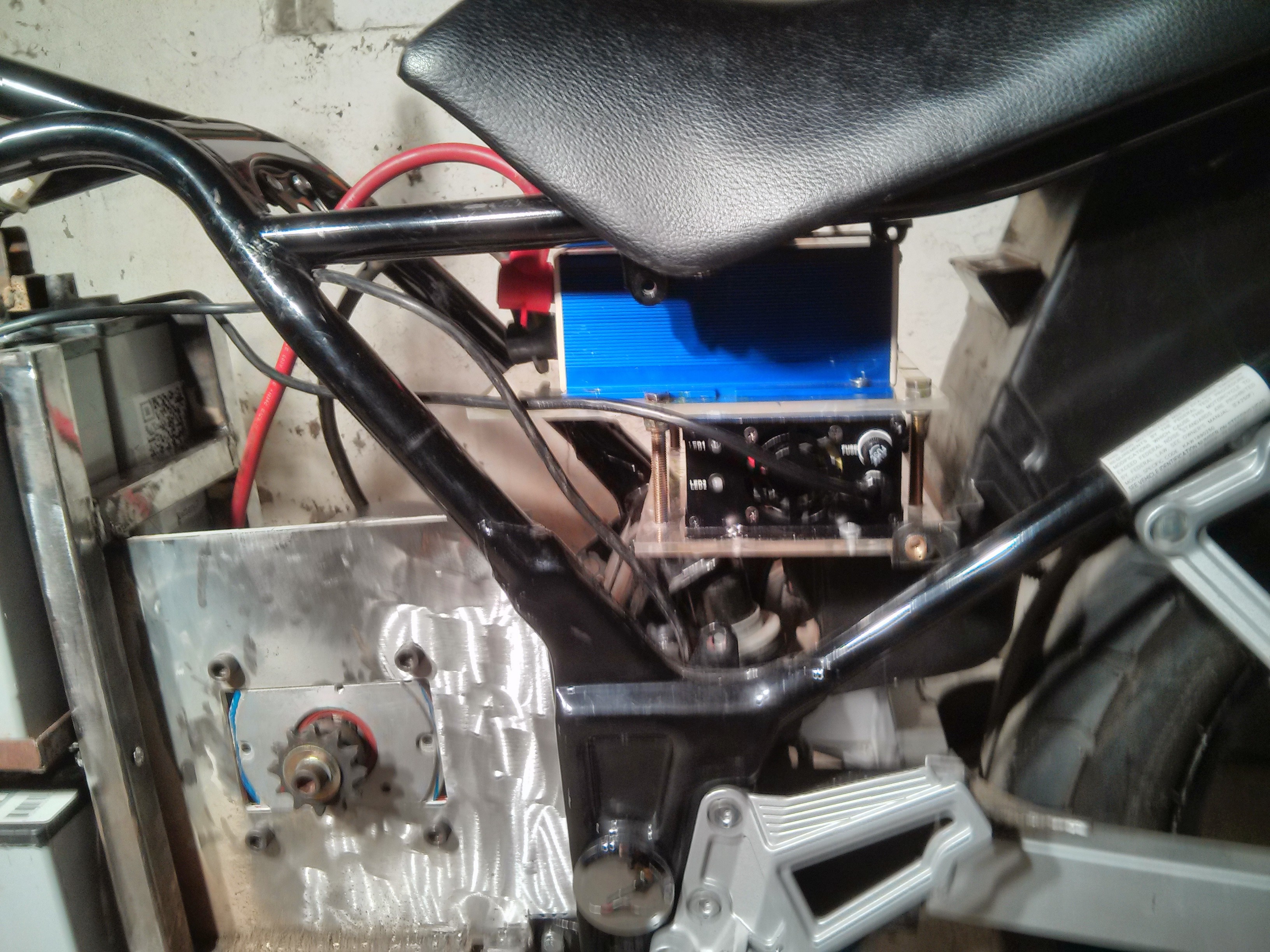
    With the frame and batteries mounted, it was time to test the motor. I should have waited for the motor controller to come in, but I may have been a little excited and just plugged the motor into the battery pack with a pair of jumper cables. Motor controller and charger arrived and get a custom acrylic mounting shelf, that bolts into some existing bolt holes in the frame.

    The next couple months were mostly wiring up the legacy 12 volt systems, and the high voltage for the drive motor. I was lax in taking pictures at this point.

    After a long day of running new wires and figuring out pinouts on existing switches, buttons, and levers, I decided to have a seat on the bike. Looking down I had one of those interesting perspective shifts on the project. It went something along the lines of, "Wow you really are a fool, you're going to take a pile of batteries, a big permanent magnet motor and some Arduino code and you are going to sit on it, and then ride it on public roads." Yup, that's the plan!

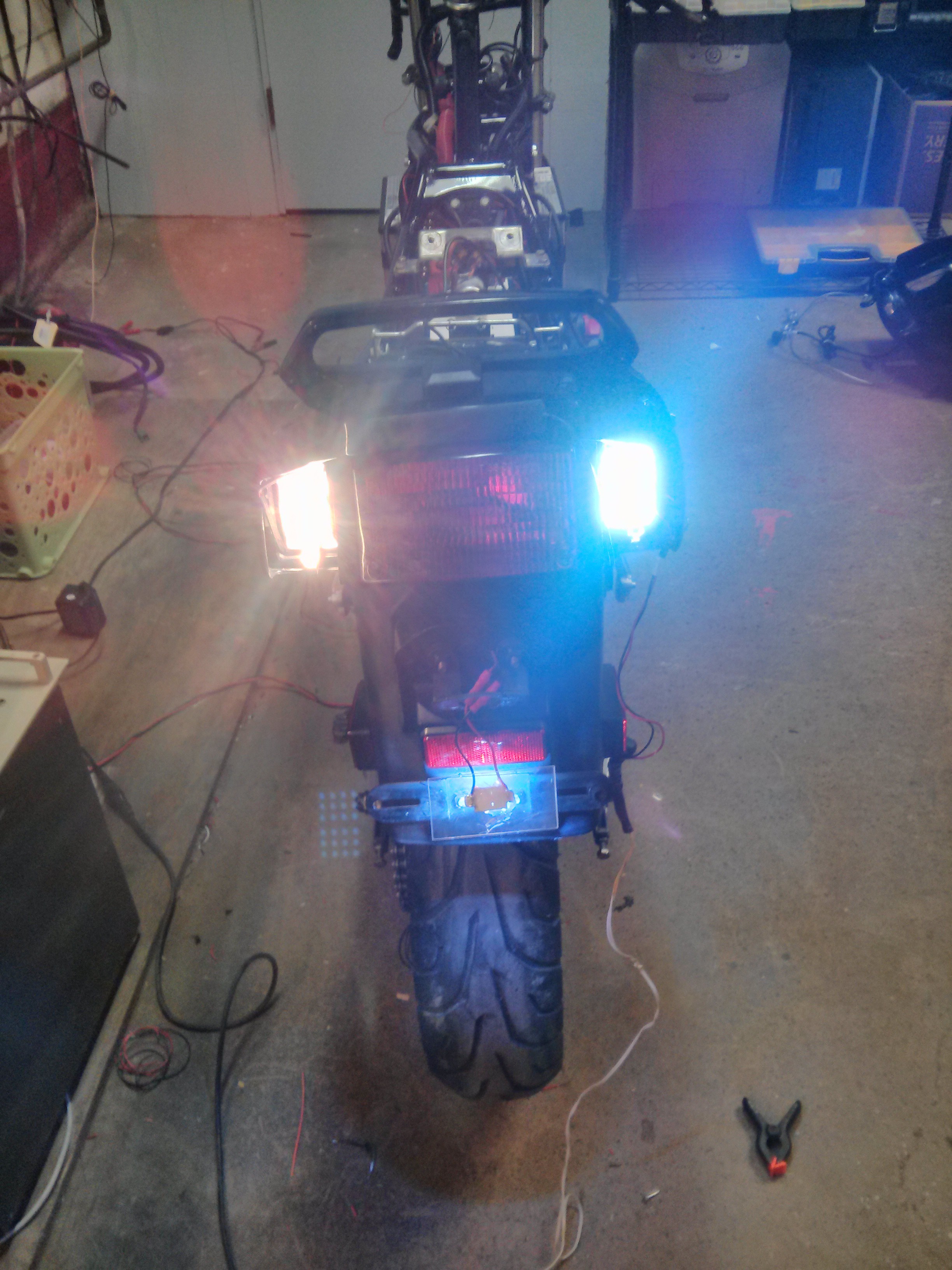
    While I was wiring up the 12 volt lights I took the opportunity to replace a large amount of them with small LED arrays. These were purchased off eBay from China for about $1.50 a pop, they are designed as dome light replacements but are small PCB's with a array of white LED's that run of 12 volt, couldn't have made a better drop in replacement if I tried and certainly not for $1.50 shipped. On the left you can see the incandescent bulb and on the right you can see the LED.

    The only mechanical...

    Read more »

View all 10 project logs

Enjoy this project?

Share

Discussions

taniasa7044 wrote 09/22/2024 at 12:50 point

Our strategy is based on the notion that anyone can become an expert tax manager given the correct resources. Whether you are an experienced company owner or a first-time tax filer, we provide customised insights and easy-to-use tools to help you stay compliant, make wise financial decisions, and optimise your returns—all without depending only on outside experts.  https://mytaxdaily.au/

  Are you sure? yes | no

Nicholas DiVitto wrote 10/10/2017 at 20:52 point

Sorry if I missed it, but what motor controller are you using?

  Are you sure? yes | no

Adam Curtis wrote 11/06/2015 at 15:00 point

Looks sweet! Check out my 1974 Saab Sonett Conversion, I'd love your thoughts/suggestions.

Adam

  Are you sure? yes | no

Jordan wrote 05/18/2015 at 14:31 point

that bike is dying for some EL tape to bring out its inner electric blue highlights. just saying. 

  Are you sure? yes | no

ErikL wrote 05/18/2015 at 15:50 point

That could be really cool. I was debating taking a page from the BMW i series and adding electric blue highlights along the front fairing edges where the air intakes used to be.

  Are you sure? yes | no

joey wrote 03/25/2015 at 14:33 point

Saw this bike up close. He did a very good job.

  Are you sure? yes | no

adam_t_watson wrote 03/11/2015 at 21:54 point

I crashed one of these bikes into a mini-bus - then I sold the wreck to a guy - it caught fire when he was fixing it and burnt down his shed and nearly his house. I don't miss that bike. Interesting project though.

  Are you sure? yes | no

Danny wrote 03/25/2015 at 11:23 point

funny, when I was fixing mine I nearly burned down my shed too! (too much easy start = fire in the air box)

Will follow this project with interest as I have a baby ninja (ex-250-H) (full fared ZZR one) that requires either valve seat replacement, or something doing something fun with it.

  Are you sure? yes | no

Øystein wrote 02/26/2015 at 00:51 point

Nice build log and awesome implementation of the neopixels in the charging port!

  Are you sure? yes | no

suicidal.banana wrote 02/16/2015 at 15:57 point

Great build log!

  Are you sure? yes | no

Similar Projects

Does this project spark your interest?

Become a member to follow this project and never miss any updates