Close
0%
0%

Multichannel Audio DSP Field Mixer Recorder

bluetooth app controlled professional portable DSP mixer.balanced audio IO,phantom power,flexible routing,ISO recording. timcode. AVB audio.

Public Chat
Similar projects worth following
Multichannel 8 channel + Professional Field RecorderDSP mix routing and FX.Backpackable!100% app controlled. website for app and firmware updates ( eventually ) http://www.bbbox.co.uk
http://www.bluezombie.co.uk

Android and IOS App used to monitor audio levels and mixer settings. Rig up a car , set up the mixer settings and hit record.....Maybe you never see your mixer again because your working on a documentary with suspect characters.. but , it didn't cost as much as you main mixer and life goes on ;)

record your bands live gig and set the mix levels on your phone in the sound check ?

use it with your DAW in your home studio

design your own custom analogue cards and plug them in !

small , low power , lightweight , customizable , low cost

Future bluetooth hardware knob controller.

NEW DIGIBOARD , DSP XMOS STM32H7 , USBC, GB ETHERNET, TWIN SD CARDS, TC IO, TXCO RTC
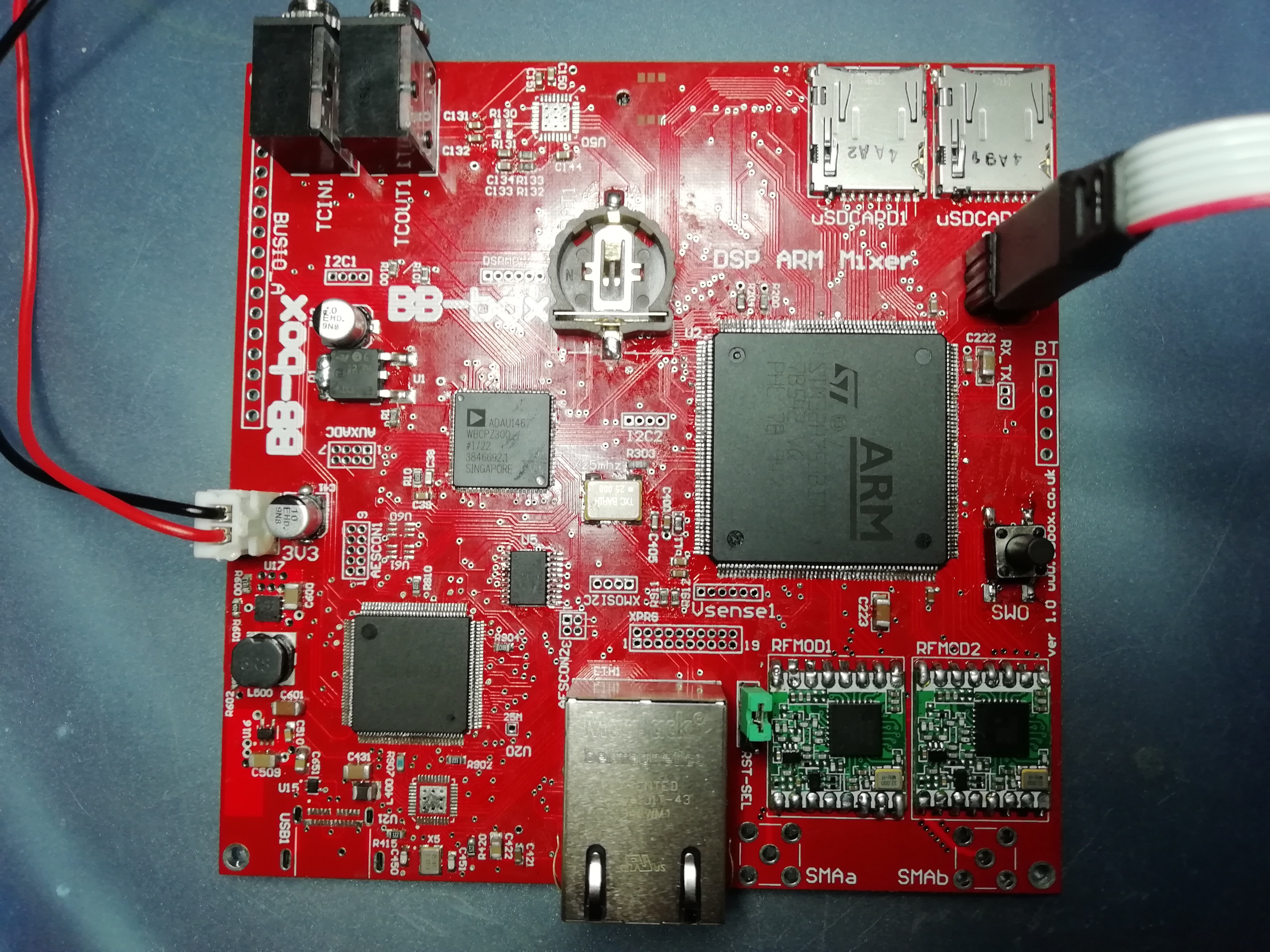
NEW DIGIBOARD

8 channels AES3

AVB gigabit ethernet audio

AES3 IO

USB C PC/MAC DAW connectivity

TXCO RTC for accurate time of day ( Timecode )

Individual Timecode IO , JamSync

Dual RF modules for digital audio link to camera ( or possible timecode to sync boxes )


NEW ANALOGUE BOARD 

isolated digi opto power switching for the preamps ( power saving )

8 balanced 10 - 65db preamp cards on 1.27mm headers ( phantom power and 0db line level ) 

4 balanced line drivers cards

2 x very high quality headphone cards.

preamp front end limiters

Voltage monitoring

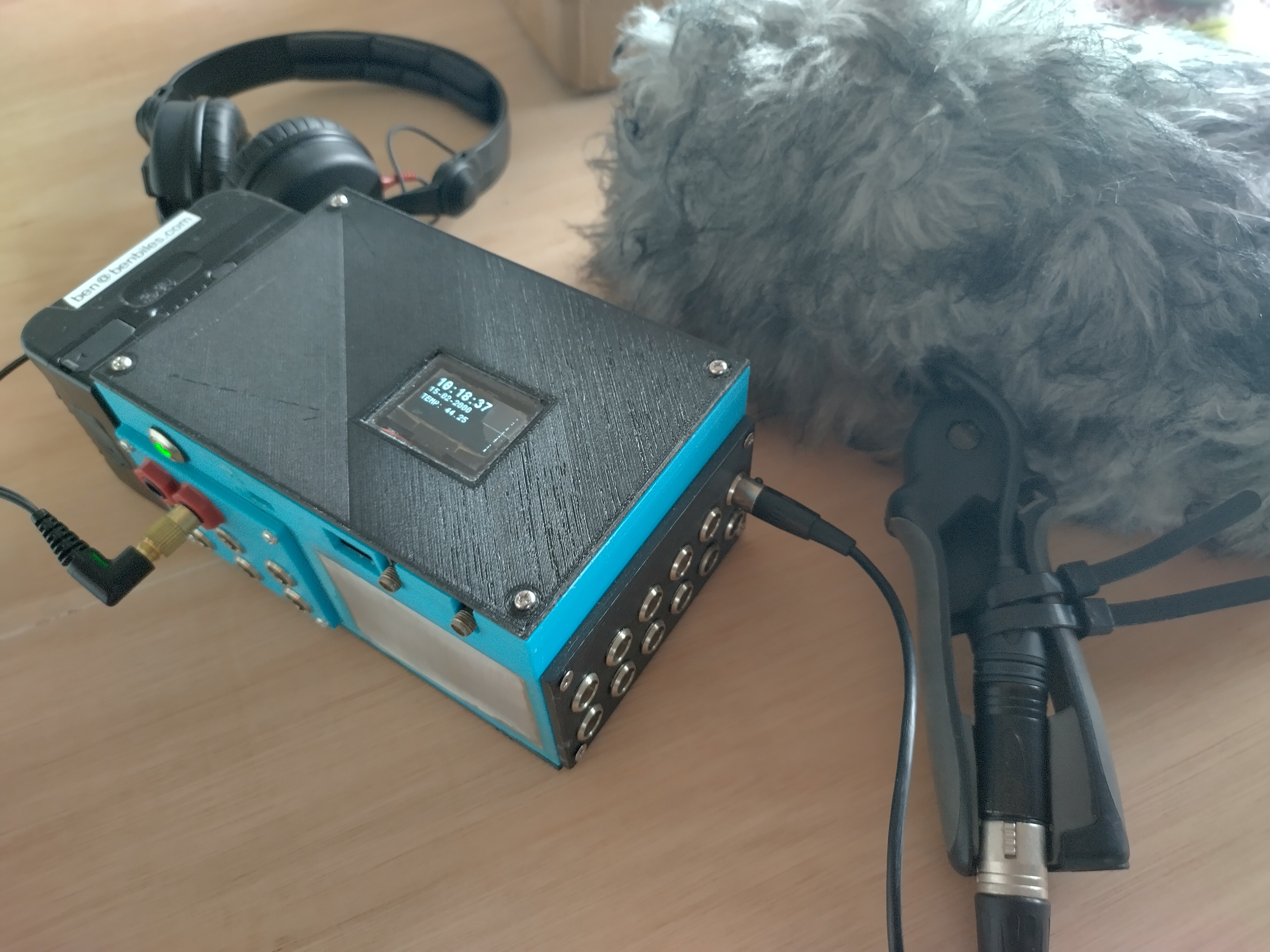
started printing 3d cases to try and get a design worth making out of aluminium or carbon fibre.

experimenting with changeable connector plates.

It's Alive !!! here's the 1st test recording for historic reasons :) 

https://soundcloud.com/benbiles/bbbox-proto1-recording-48khz16bitwav

here's an old real-time audio meter input demo. was another mile stone!

The Bluetooth App does a lot more now also ! FX compressors LP HP filters etc.

_______________________________________________________________

The beginning , learning how to use SPI and I2C. I believe this ever worked :) 

  • 1 × ADAU1467 Semiconductors and Integrated Circuits / Misc. Semiconductors and Integrated Circuits
  • 1 × ARM STM32H7xxxx
  • 1 × Fan out Buffer
  • 1 × 12.288mhz oscilator
  • 1 × CS4385 Audio ICs / Audio Digital to Analog Converters (DACs)

View all 8 components

  • weird DAC output fixed

    ben biles11/30/2023 at 10:00 0 comments

    I must have blown the DAC by inserting a car incorrectly at some point.

    changed the DAC IC and its sounding GREAT!!

    I have the balanced outputs going into a Tascam LA40 mk2 so I can listen to the outputs on monitors and I'm using an old Behringer 4 channel Ultra Pro DI rack for testing mixing lots of channels at the same time.

    The idea is I actually use this box for PC TV Alexa and whatever rubbish I use at home to test long term stability. does it crash , over heat and all that ! so far so good.

    I've set the main faders to mix from -inf dB to +16dB and the main output faders from -inf dB to +18dB

  • Line Driver buffer clipping

    ben biles11/27/2023 at 00:27 0 comments

    I have only just found time to check the differential line drivers cards. They are way off !!

    I have clipping on one side.

    I have measured after the DC blocking caps between the biased buffer op amp and the line driver IC ( That 1606 ) 

    I think I need to check what's happening before the blocking caps now and try and figure out why the output of the buffer opamp is 1.25V peek on one rail and clipping at 1V on the other !

  • 8 pre amp cards loaded !

    ben biles03/19/2023 at 18:18 0 comments

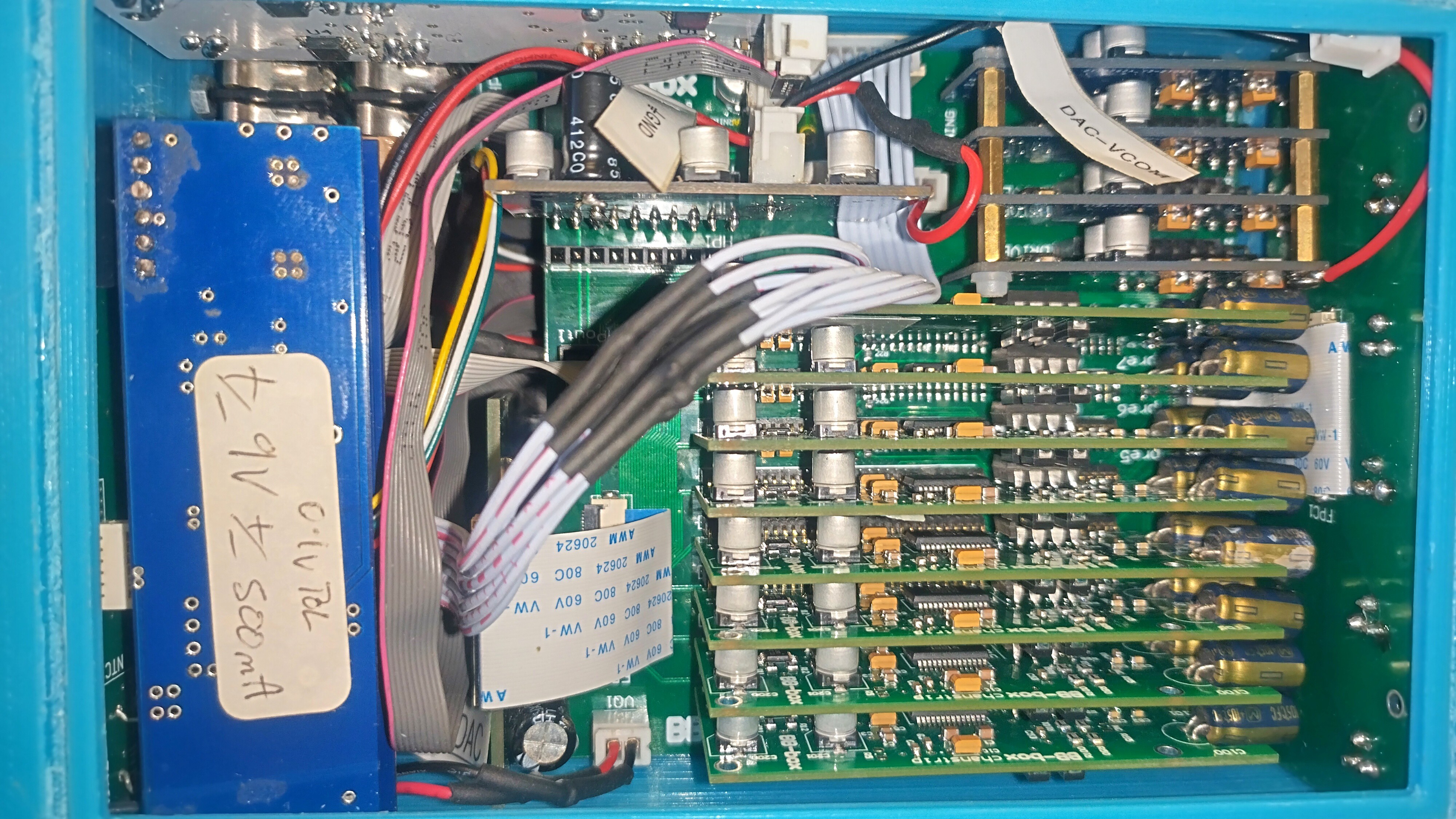
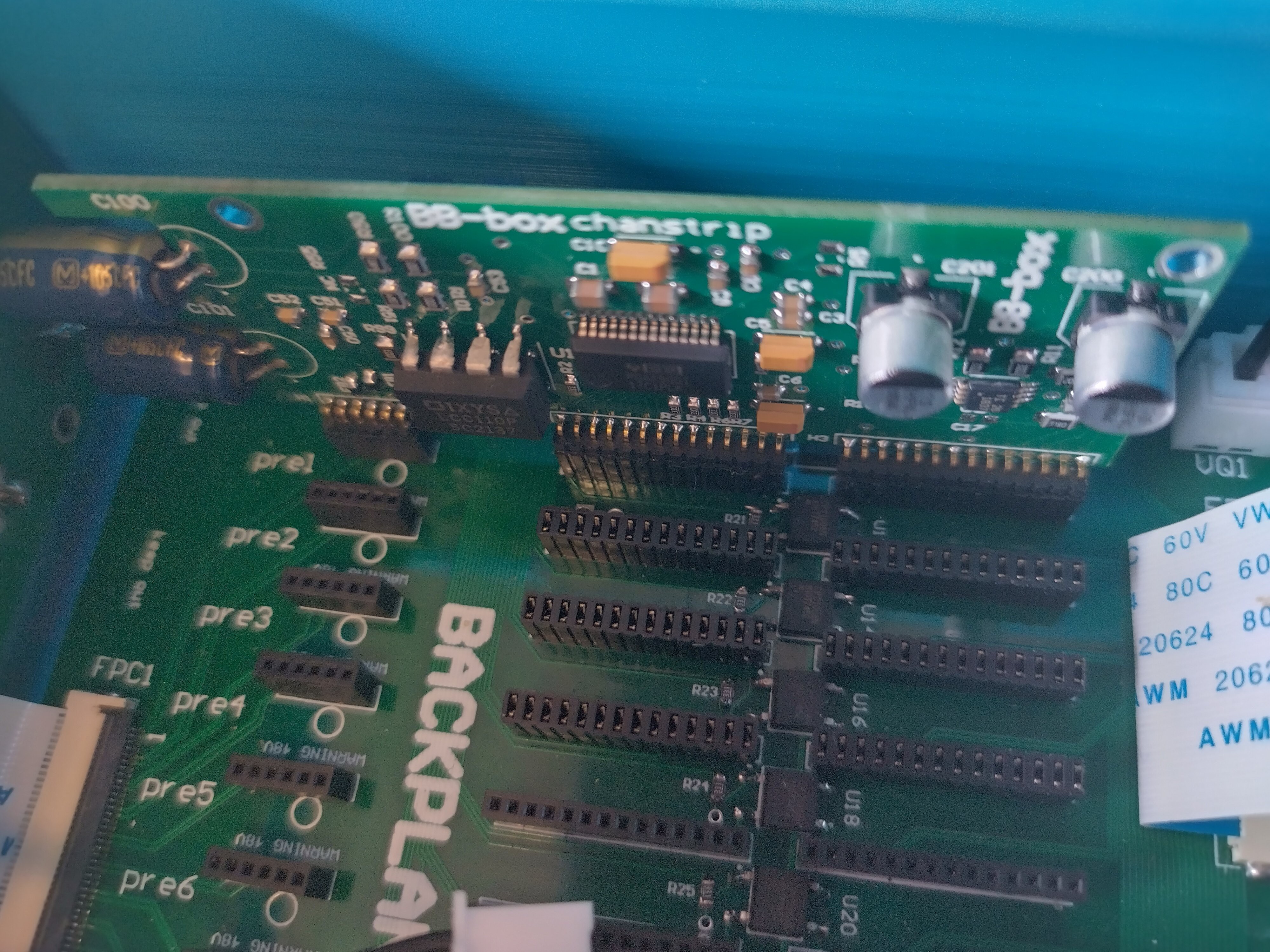
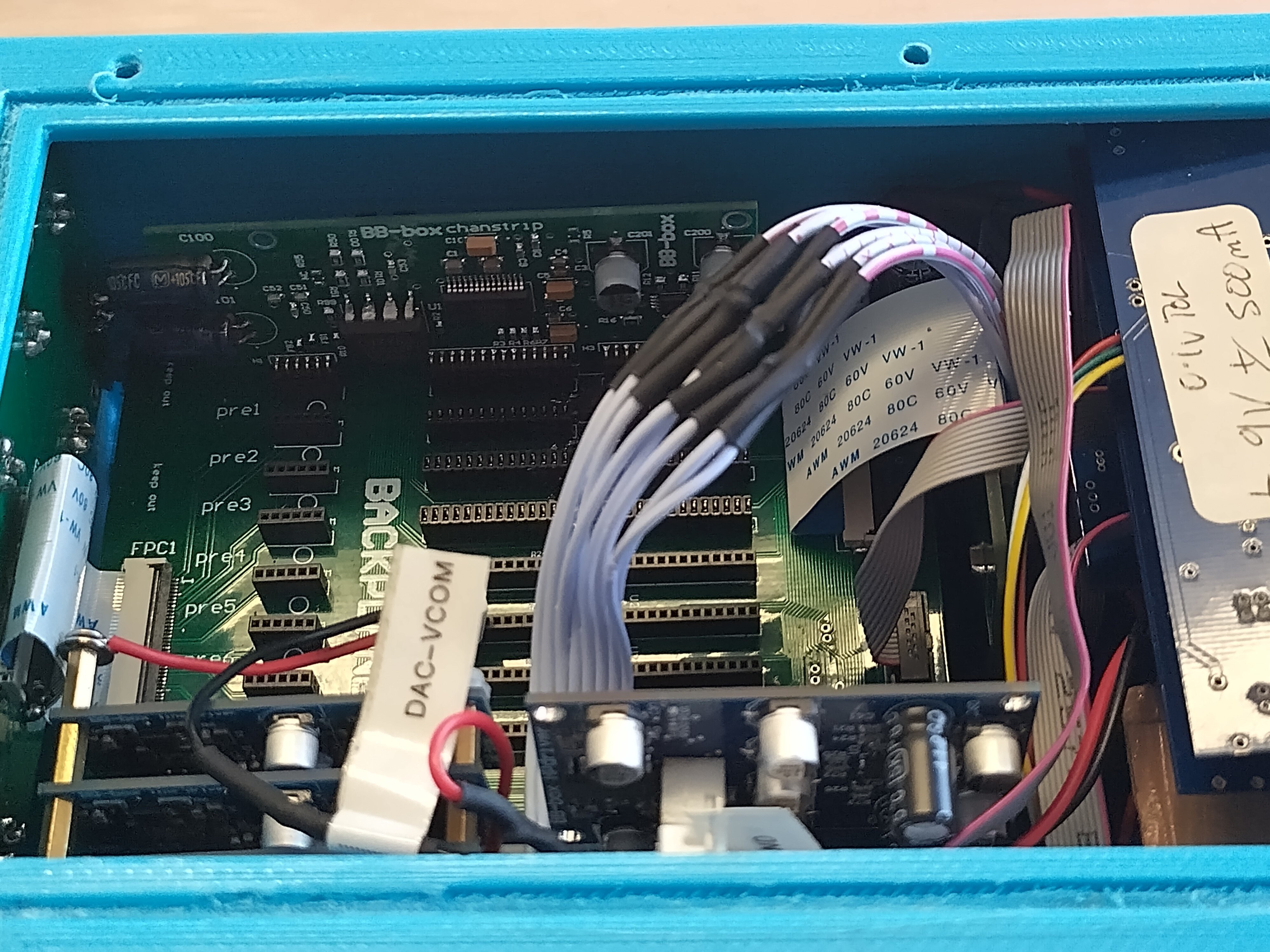
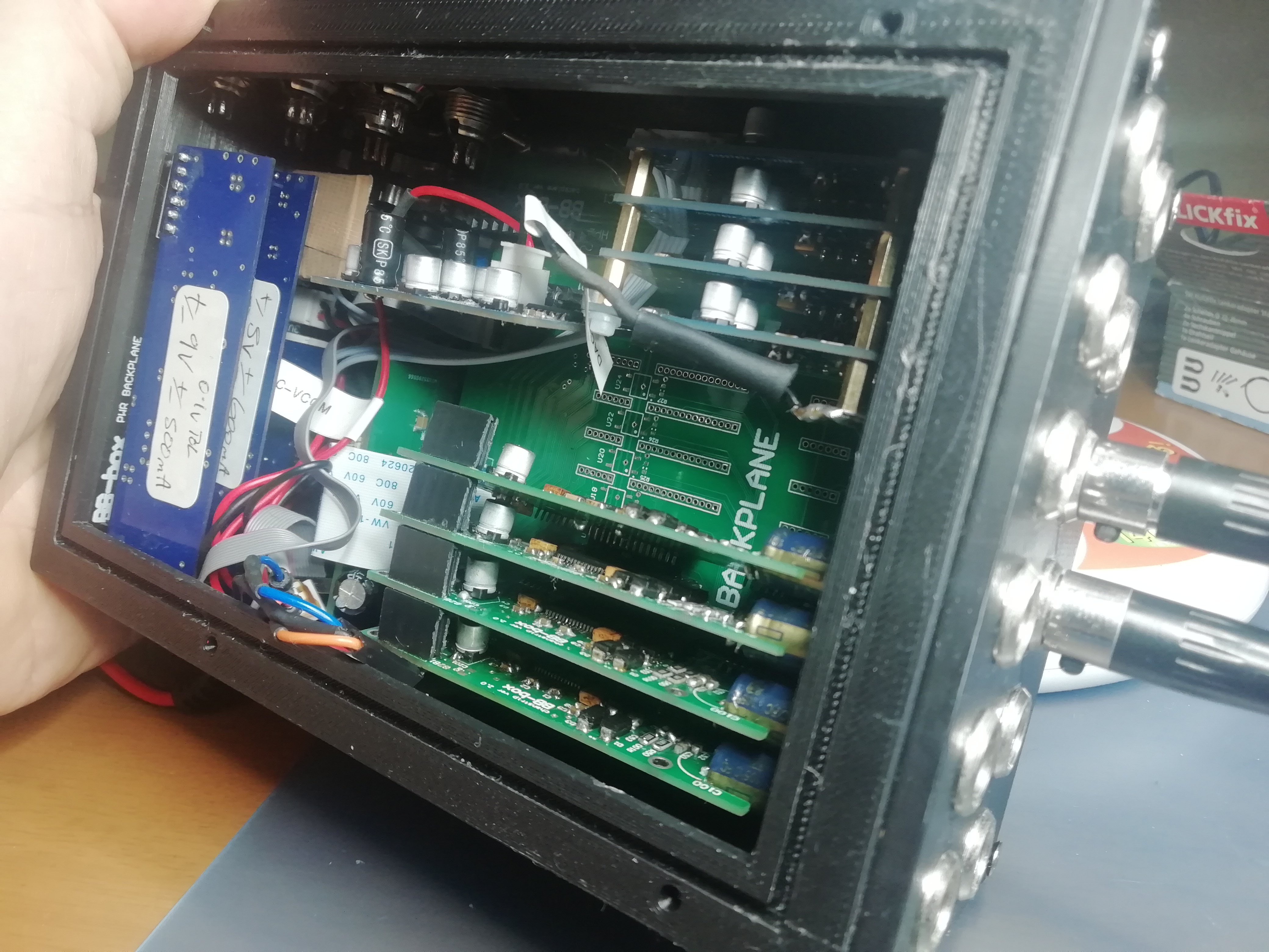
    Here's a pic of all 8 preamp cards with 4 balanced line driver card loaded. 

    The headphone card gets warm , so I'm only running 1. 

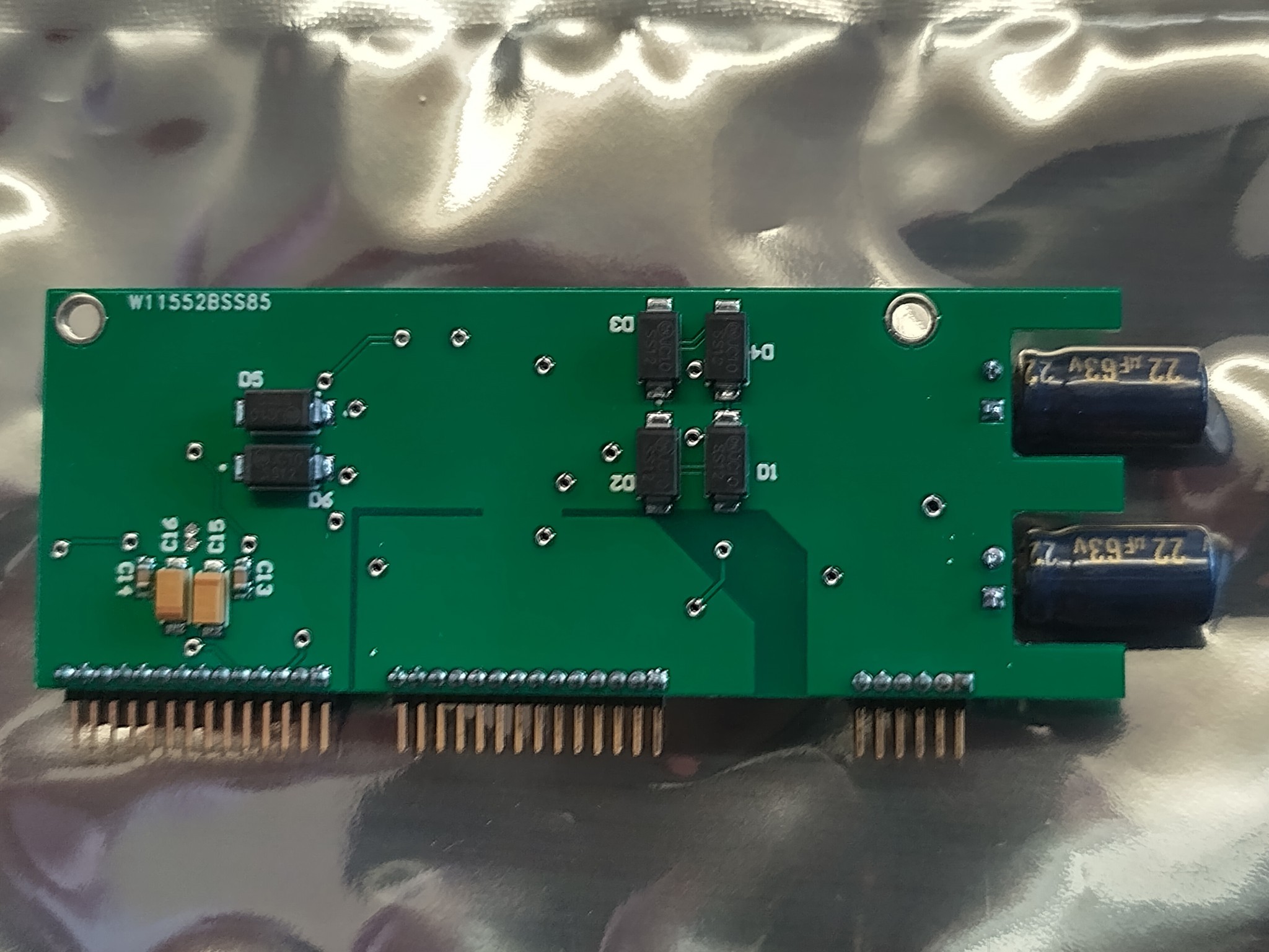
    The protection diodes on the rear of the preamp cards are in the way of the SMD electrolytic caps ( they moving over about 10mm )

    They were added to protect the PG2500's against voltage rail error !

    The next job is to code the +-5v rail monitoring on the MC and have all the channels immediately shut down if there is a

    voltage rail deviation > 0.1V

    The would have preferred there protection diodes to be on there too ! next revision I'll move them over 10mn so they are well

    clear.

    This is all part of learning how to build multi board designs ! 

    The gap between the balanced line drivers and preamps is tight but ok.

    you can see the analogue IO panel FPC connector just fits.

    I'm thinking of stripping a lot of the 3d printed box away so it's just a frame and then

    using aluminium panels to make up the sides and connector panels of the box. 

  • my 1st manufactured PCB cards !

    ben biles01/08/2023 at 15:54 0 comments

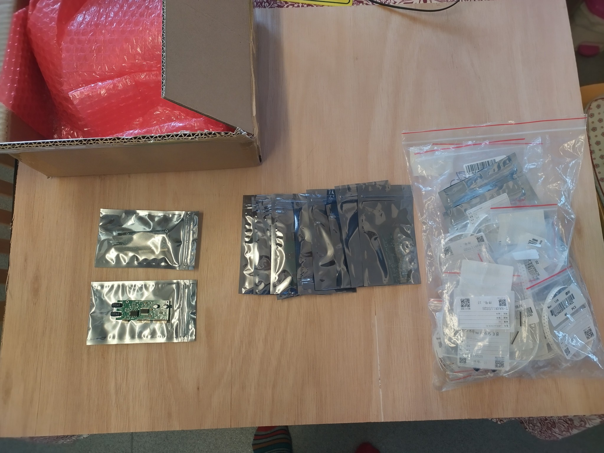
    Exciting times :) !!   I have ordered my 1st run of cards at PCBway pick and place ! 

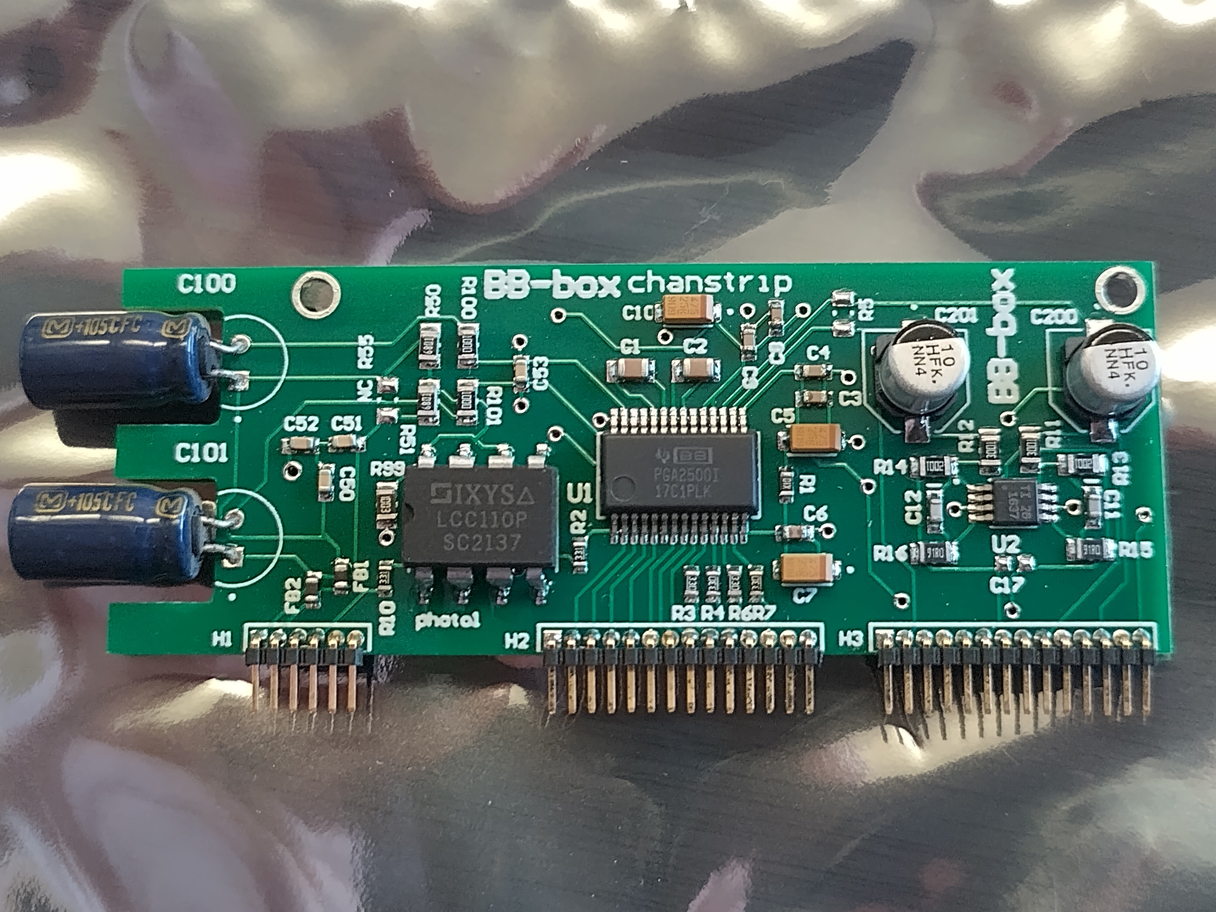
    Here are my 1st ever professionally manufactured boards :) 

    There are only 10 cards , but the parts are not cheap ! 

    https://www.pcbway.com/assembly-process.html did an amazing job here guiding me through the world of having a correct BOM ( bill of materials ) and checking everything from part orientation to proper part / footprint matching !

    They part sponsored the project by reducing the pick n place / manufacture cost by 50% which was really helpful. This is not why I am writing a positive review about them though. I am free to write what I want here !

    They really did have a ton of patience with me and my stupid mistakes on this. I can't recommend you use this service enough if you have never had a board professionally manufactured. You can send your own parts or have them source the parts locally. some parts I had to send them as they are difficult to source in China due to the current situation. but its easy to send parts directly to them.

    On this version of the preamp I have VCOM from ADC coming in through the connectors.

    I also reduced the size of the phantom blocking caps as it was taking to long to drain them and causing problems with the PGA2500. The lower value 22uF blocking caps should slightly increase bass filtering slightly but so far I can't tell the difference from using these or the 47uF blocking caps. apart from the faster drain time when phantom power is switched off. When phantom power is switched off or on the DSP mutes the inputs for 1 second in case of large banging noise etc. this time was reduced using the smaller blocking caps.

    I need to glue the caps onto the PCB myself but I opted to do this myself to save time.

    As you can see the solder reflow is really nice !!! especially on the PGA2500 and OPA1637

    diode protection on rear for power protection and phantom power short protection

    One thing I can say , using KiCad you often just choose a generic symbol / footprint for resistor or capacitor etc and have in the back of your mind what actual part you will use. this is really bad practice since when you output your BOM there are to many empty holes as far as manufacturing are concerned. it might be just a 10k 0603 resistor to you , but they need to know exactly what part to order for you !!!!! its so easy to overlook when outputting a BOM ! worse still a really bad habit of mine is to just use say a resistor footprint for say a capacitor or ferrite bead !! don't do it !! you will forget and the factory could easily choose the wrong component.

    Anyway , thanks to PCBway they fixed my stupid mistakes and got me some really nice working preamps for the BBBOX mixer recorder.

    here's a few pics of a card inserted ! 

    note , FPC cables to ADC/DAC card and ext connectors to :)

  • switching battery / ACDC adapter testing

    ben biles12/01/2022 at 10:40 0 comments

    SEE PREVIOUS LOG FOR DESIGN NOTES

    Its working but next revision I think I will change the priority to the mains ACDC power input if both battery and wall adapter are plugged in! basically swap the 2 power input wires around :)

  • battery to dc wall adapter switch !!

    ben biles10/17/2022 at 04:13 0 comments

    it never ends !! :)

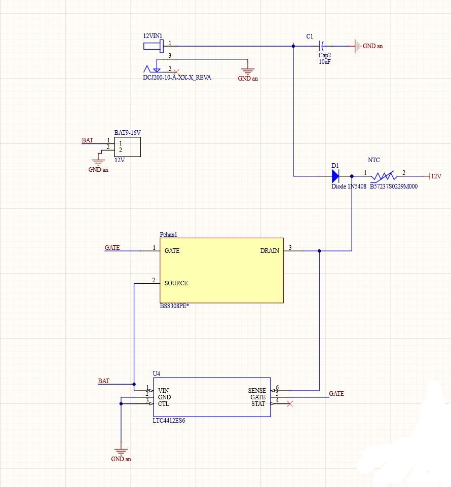
    now I need a battery / acdc wall adapter power switch. I'm not charging the V-lock battery's on board as people generally use there own proper chargers.

    I also include NTC protection [ edit ,  PTC resettable fuse , not NTC ! ) ]  in case there is ever a short somewhere !!

    I'm going to try using the LTC4412 to switch a BSS308 ( P channel mosfet )

    more cost and more complexity !

    does anyone know of a cheaper simpler way that takes up little pcb space ?

    I could just switch the mosfet with the mechanical DC barrel jack switch but seams a bit risky ?

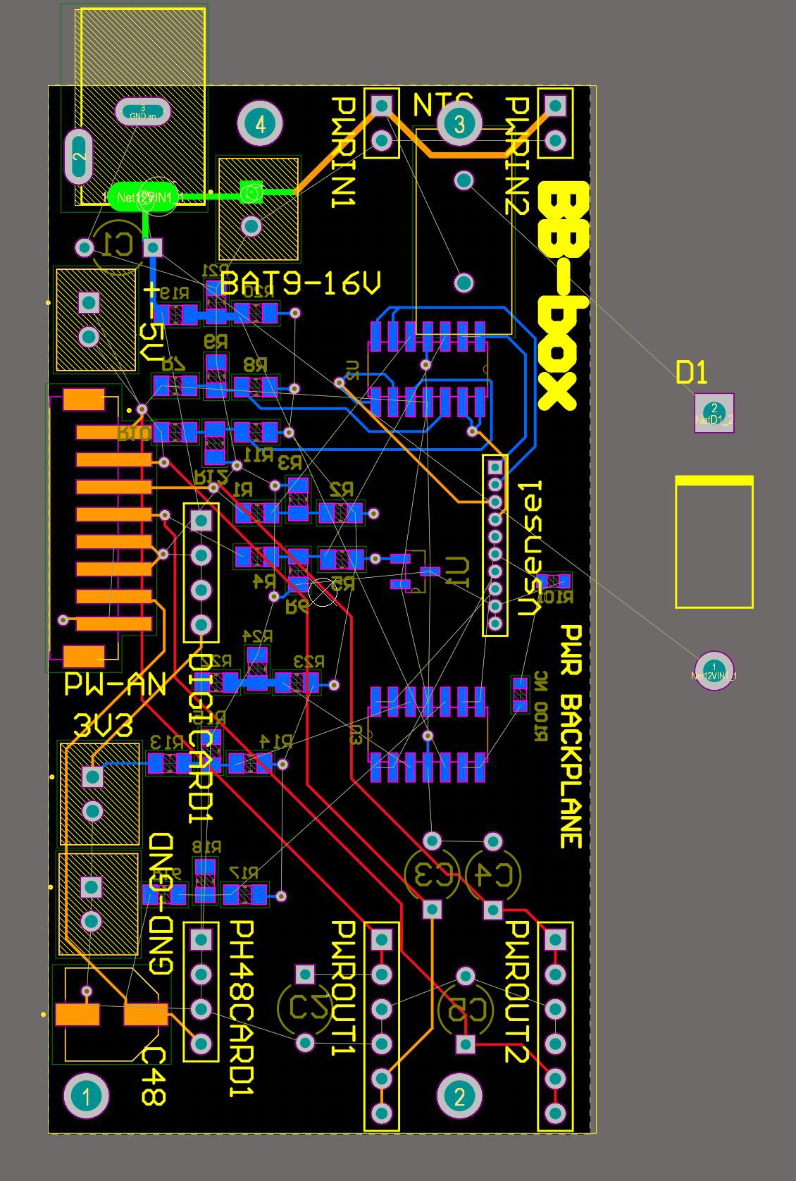
    My backplane is already pretty loaded with voltage level monitoring / ADC buffering so I'm making it 4 layer this time and with components will be on both sides. the vsense1 socket will send the buffered 0 - 3.3v voltages to the MC. the digi main board only has 6 ADC channels hooked up at the moment but eventually that will be upgraded to 8 , that way I can monitor battery Vin ( DC vin ) +-15 +-5 48v 3.3v and more

    the diode in this example obviously doesn't fit this design !! I'm sure I will find a decent heavy duty

    SMD version.

    ahhhh , I'll make it all fit , there is always a way ! 

  • BB-Box gets a V-Lock pro battery 99 W/h , plane safe !

    ben biles03/14/2022 at 07:48 0 comments

    BB-Box gets a V-Lock pro battery 99 W/h , plane safe ! 

  • preamp / line driver and HP cards in with +/-9v opa1637 buffers biased from VQ on ADC and DAC

    ben biles10/06/2021 at 13:38 0 comments

    4 preamp cards and 4 balanced line drivers using OPA1637.

    The Vcom and higher +/-9v rails for OPA1637 buffer are supplied through the stackable headers on the preamp cards. They are 1mm to long so not sure I will be able to squeeze all 8 preamps in there using those. 

    The 6mm brass standoffs worked fine for the line drivers and I send the VQ down one line of brass standoffs and it works. 

  • more work on the chassis / box

    ben biles09/26/2021 at 12:18 0 comments

    I've started work on the case again and will print another in CF and will glue on some thin aluminium panels in recesses in the CF.

    I am making plates for connectors that bolt to the chassis. so far only 2 plates , 1 for the mini XLR inputs / outputs and 1 panel for the AES IO mini XLR and 1/4" headphone sockets.

    I made some slots in the digital and analogue main board mounts so I can slide in some EMI shielding between the 2 boards.

    this is a very rough 3d thing of the assembly. you can click to make a cutaway.

    https://grabcad.com/library/bbbox-1

  • more work on the chassis / box

    ben biles09/26/2021 at 12:18 0 comments

    I've started work on the case again and will print another in CF and add some aluminium panels.

    I am making plates for connectors that bolt to the chassis. so far only 2 plates , 1 for the mini XLR inputs / outputs and 1 panel for the AES IO mini XLR and 1/4" headphone sockets.

    I have no idea if this 3d grab cad page will embed but its a rough idea!

    https://grabcad.com/library/bbbox-1

View all 99 project logs

  • 1
    Step 1

    BUY KIT WITH PRE ASSEMBLED CARDS WHEN ITS RELEASED.

    STEP 2

    ADD YOUR OWN DESIGNED ANALOGUE CARDS following IO guide or BUY PRE ASSEMBLED.

    STEP 3

    3D PRINT BOX or buy CARBON FIBRE one from here

    STEP 4

    INSTALL APP ON TABLET OR PHONE AND MIX / RECORD MULTICHANNEL AUDIO and USE AS AN AUDIO INTERFACE ON YOUR DAW ! 

    Hopefully I will eventually sell pre made modular boards of this mixer recorder.

    Users will be able to use pre existing firmware or write their own. 

View all instructions

Enjoy this project?

Share

Discussions

victor.crestani wrote 05/12/2022 at 22:52 point

Hi Ben, I've been coming back at your project from time to time for the past two years because it's quite close to something I've been working on. I'm designing what is for now a 10 channel (+2 line) portable, battery powered mixing desk for movie recording. It was analog at first and  became a digital mixer. I kept the analog controlled mic pre (although I'm thinking about a design with a VCA controlled mic pre with an integrated limiter and digital gain control through VC preamp gain), filters and limiters. The adcs comes right after the limiters.

I've been thinking on rather going with the same ADAU1467 and STM32H7 design that you've been using for the digital part or rather sticking to only using an STM32H7 and doing everything from there.  Do you know if the STM32 itself could be usable as a DSP for that project ?

To give you an idea, I would need to input 16 channels into the DSP and have 18 outs. And an idea would be in the futur to expand it to 24 channels in and 26 outs to add 8 AES EBU I/Os.

It's worth pointing that the 8 SRC inputs on the ADAU would be perfect for AES inputs.

I've been trying to find any infos on if it's possible to go in and out the STM32 through TDM8 or 16. Given that I didn't find any informations on it, do you know if it's doable ?

What seems to be one of the STM32 biggest limitation is that it actually lacks enought inputs to design audio mixers.

For the background story, that project is my master thesis work but has started going way further than that.

I'm actually a sound engineer rather than an electronic student, and designing that kind of stuff is something that I've been learning on my own.

Thanks for you help ! And for sharing your work here, it has been very interesting to look at.

  Are you sure? yes | no

ben biles wrote 05/22/2022 at 14:03 point

stm32 has SAI ( serial audio interface ) which you can configure as TDMn. I believe you can mix audio with DSP instructions included in ARM but how reliable that is or if DSP instruction set is still properly maintained is all unclear for me. I decided to use the DSP so I can chain FX into the mix and I think this would really overload DSP instructions in ARM and I didn't want to risk getting into latency issues. I have made a filter using ARM DSP instructions before but only one channel. when you say STM32H7xxxx there is quite a wide choice of chips with different number of SAI ports with some maybe having none! There are some tricks the M7 cortex chips use with RAM . predictive ram caching etc  so you will need to read about that also and clear predictive cache or assign RAM for the DMA transfer buffers . I would start with an M4 cortex chip and just try to hook up a codec (ADC and DAC ) to it and add an SD card and see of you can record and playback some audio to begin with. choose a dev STM32xxx dev board that has a micro that includes SAI ports , enough DMA channels and already has a micro SD card on there. you can get a head start with cubeMX to auto generate a lot of what you need. you will need to write / hack C code so if you don't already know how to write C then get a book and learn it ;) I avoided it for a while trying to get away with arduino etc , but you just need to get to the baremetal in the end , sorry I can't help much more than that at the moment but I think that gives you pointers to start with. excuse the C pun :)

  Are you sure? yes | no

ben biles wrote 05/22/2022 at 14:08 point

I should also say , there is always FPGA ! sound devices uses Zynq-7000 , I just felt that I wanted to make something less bound up to one company and there tools and I wanted to learn other hardware. but FPGA is still a pretty good option and with Zynq-7000 you get the ARM and the FPGA on the same chip ! good luck buying wither STM32xxx or FPGA's at the moment though !!!! \

  Are you sure? yes | no

FORART fe wrote 02/19/2022 at 07:41 point

Hi Ben, just found this interesting "hack": piStudio (Portable recording studio)

https://hackaday.io/project/9530-pistudio


It could be interesting to establish some kind of collaboration between projects.

  Are you sure? yes | no

ben biles wrote 02/19/2022 at 11:26 point

thanks for the link. the console look great but I'm trying to build something much smaller and without an OS :)

  Are you sure? yes | no

FORART fe wrote 12/17/2021 at 07:09 point

Hi there, what's going on ?

Just discovered another interesting (commercial) gear to get inspiration for the rack version:

https://www.soundonsound.com/reviews/behringer-ultragain-ada-8200

Hope that inspire.

  Are you sure? yes | no

Chris Eloranta wrote 09/23/2021 at 23:14 point

So humbled and inspired by your insanely fantastic work, Ben.

I'm embarking on a project which is a spiritual subset of yours:  16ch of 24bit 48k low-latency ADC sent over a LAN along with OSC. 

Did you ever experiment with multiplexing/processing the two Cirrus chip TDM streams into a single 16ch bus/output/stream?  I scanned the project and saw it mentioned as a future goal, but I'm unclear whether it was ever implemented, and I must admit I've been stumped for a bit at that point.  (It's OK, I won't see my cirrus chips for half a year anyway due to the chip shortage; so there is time!)

Would I be correct in assuming that two Cirrus chips (CS4385) into a XMOS Core (Need to research which IC) would serve as the basis for outputting 16ch of ADC through AVB?  (I do realize that buffering circuits, clocking, power supply, microcontroller would all be involved in supporting roles as well...)  

Thanks so much for posting your project.  It seems to be the only thing out there even close to my target!

  Are you sure? yes | no

ben biles wrote 09/24/2021 at 00:22 point

Hi , your project sounds interesting. AVB to !! I am not sure you can delay by 8 32bit channels  / daisy chain for TDM16 mode with the CS5386 ( ADC ) . have a look in the datasheet and see if its possible. you might be better using  AKM AK5538 or similar. that supports daisy chain. I'm using the ADAU1467 DSP which supports multiple TDM8 or TDM16 IO. I took out the 2nd ADC from my project for now to free up some ports on the DSP.  later I will probably make a dual ADC card using TDM16 but just choose an ADC IC that supports daisy chain mode. I might also try doubling the ADC's for higher dynamic range. I'm using the Xmos X200 and I basically copied the ref design for the ethernet phy. I sounds like it should be possible to combine 2 x  CS5386 streams into the AVB stream in the Xmos200 code , but I would take a good look at the AVB reference design code 1st and try and understand the way xmos timesclice etc works 1st to see if it looks feasible. Sounds like it should be to me :)

  Are you sure? yes | no

Chris Eloranta wrote 09/24/2021 at 01:17 point

Sounds like I could use an ADAU1467 DSP like you did… 48in/48out.  Overkill for a digital bus combiner, but I’d imagine it would do the job?

Sadly, the AKM aren’t even available for backorder at this point. 

  Are you sure? yes | no

ben biles wrote 09/24/2021 at 03:50 point

Using the ADAU DSP just to combine some channels into XMOS would be a bit overkill. I would go onto the XMOS forum and ask if someone has already combined multiple TDM8 streams for AVB or other things. sounds like it should be totally doable ( possibly already in the AVB demo code ! )  ;) you can define GPIO on the xmos to control your ADC's and DAC's to so would be If quite simple hardware that way. If you want to use ADAU1467 and get stuck ask any questions you like , would be happy to help. The AD engineer forum is a great place for help to. 

  Are you sure? yes | no

FORART fe wrote 05/21/2021 at 11:43 point

Wow, black finish looks really great !

Anyway, as you know, I would really like to see a 1U rackmount version like this:

https://hackaday.io/project/163523-mls800

  Are you sure? yes | no

FORART fe wrote 03/12/2021 at 08:17 point

Some years ago we've found this interesting project(s) idea(s) that could inspire further improvements:

http://diydsd.blogspot.com/2012/03/open-ngdi-project-definition-stage.html

https://code.google.com/archive/p/open-ngdi/

(our backup: https://github.com/forart/open-ngdi)

https://groups.google.com/g/open-ngdi


As always, hope that helps/inspires !

  Are you sure? yes | no

FORART fe wrote 10/05/2020 at 08:30 point

As already suggested in the Public Chat, it would be great to adopt/collaborate with these IntRoLab's open hardware multichannel audio card projects:

https://sourceforge.net/projects/eightsoundsusb/

https://github.com/introlab/16SoundsUSB
(posted on thei GitHub too, of course: https://github.com/introlab/16SoundsUSB/issues/11)

Hope that inspires !

  Are you sure? yes | no

ben biles wrote 03/04/2021 at 23:39 point

ODAS is also a really great project from Inrolab  https://github.com/introlab/odas

I built a 4 channel direction finder that uses odas :)

  Are you sure? yes | no

jackiredale wrote 03/23/2019 at 01:08 point

This project is amazing , I would love to have a go at making one myself , are you going to sell diy kits or the pcbs ?

  Are you sure? yes | no

ben biles wrote 04/08/2019 at 17:22 point

Hi jackiredale, sorry for the late reply. 

I was thinking of selling the 4 layer digital main board and ADC-DAC card modules with the firmware / android app already populated later when I've properly got everything working and tested. I don't really want to sell a board with problems :) so far I only found one error and there was an easy work around on this revision of the 4 layer digi main board but there are loads of gremlins on the other 10 or so module boards!

I am also working towards a final bluetooth only field recorder in a waterproof box that I want to give away to sound recordist friends that work in TV film etc. Idea being they could help me fine tune the thing and eventually get some kind of useful thing to sell ! no idea of the channel count or anything yet until I get the timecode / realtime metering working on the app. I got the test tone and test sweep 20hz -> 20khz working today :) pretty cool !

The sound quality is awsome from the preamps / headphone combination. better than my sound devices mixer. One thing though. I'm not using differential op amp buffer between ADC and PGA2500's ( just Panasonic FC DC blocking caps as in datasheet ) but this might not suite other preamp designs. usually you would have the op amp buffer to protect you ADC inputs from DC bias. So that might be annoying for people that want to add there own analogue hardware. 

on a plus side the ADC/DAC cards have split ground plane and there is really no noise coming across into the analogue from digital which I'm really happy about.

If I sell the mainboards I suppose I'll just do that here though hackaday but no idea how that works :)

have you seen this site ? http://www.freedsp.cc/ I think they have some pretty cool DSP boards that are open source and one that works with rasbery pi ? that might also work as an audio recorder although i'm not sure.

  Are you sure? yes | no

Ulysse wrote 04/22/2017 at 16:16 point

I like. Of course. Music !

  Are you sure? yes | no

Craig Hissett wrote 04/22/2017 at 15:56 point

This is great matey!

  Are you sure? yes | no

Yann Guidon / YGDES wrote 04/22/2017 at 13:38 point

Impressive development !

  Are you sure? yes | no

Francesco wrote 02/21/2017 at 13:44 point

Hi Ben, i have a question for you. I'm working on a similar project, taking a lot of inspiration from yours. You say you're controlling the ADAU1446 with arduino via i2c. I didn't find any specification about it, the datasheet only says "program it with sigmastudio" without giving any information about i2c via an external controller. Did you found some more information? Or do you have any tip for me, how to do it?

Many, many thanks... and again, your project is awesome!

Francesco

  Are you sure? yes | no

ben biles wrote 02/21/2017 at 14:09 point

https://ez.analog.com/servlet/JiveServlet/download/1806-3-5949/SigmaStudio Basic uC Integration Tutorial.pdf

You create files from sigmastudio when you have made your design. you need to add macros to SigmaStudioFW.h so that that the code can write / read to I2C depending on the platform you are using. So in arduino that would be  Wire.beginTransmission(44); // transmit to device #44 (0x2c)// device address is specified in datasheet
  
  Wire.write(val);             // sends value byte

  Wire.endTransmission();     // stop transmitting

sorry , I have no idea how hackaday does the formating , if I try and paste code into this box I get some rediculas things happening including user names poping up ?

I switched to intel edison recently and so I'm adding mraa I2C macros to SigmaStudioFW.h now since I need a micro that can record / playback TDM 8 channel audio. I could not find any way to record high quality multichannel audio in arduino. Not to say there is'nt a way. everyone points to teensy but I am interested in 24bit 96khz 8 channel audio etc..In fact I never added the macros for arduino athough I did get arduino & bluetooth controlling the preamp with SPI and of course controlled the DSP basic initialize power on to get the board working with I2C. I had some confussion with I2C in the begining but it turned out to be a faulty board ( heat damaged by myself ) . I have the board working in selfboot mode also now with eprom :)

  Are you sure? yes | no

ben biles wrote 02/21/2017 at 14:12 point

Also I don't see your project on hackaday , can I take a look anywhere ? sounds cool ! what ADC / DAC 's are you using ? 

  Are you sure? yes | no

Francesco wrote 02/21/2017 at 22:50 point

First of all, many many thanks for your answer, that's exactly what i was looking for and i simply missed it. Now everything is much more clear for me :)

My project is very similar to yours, i'm not interested in recording but in general my goal is to build a digital audio mixer. At the moment, it's only theoretical, i'm waiting for the components i ordered some weeks ago from china. My choices are an ADAU1442 (pretty much the same as your 1446) and your same ADC/DAC. I was interested in 8 ch TDM converters and this two are the most common. For example, the "behringher x32" mixer uses those converters as well, they are perfect for the purpose. But I use self puilt preamps, from old projects of analog mixers.
My project is different from yours because i will use rotary encoders, motorized faders, screens and so on.... like i said, the intention is to build my own digital mixing consolle. 
When i'll begin to build things i will create a project page somewhere :) Maybe i will find something usefull to you too :D
Again, thanks for your advices and your help! Will keep you updated.
- Francesco

  Are you sure? yes | no

ben biles wrote 02/21/2017 at 23:28 point

interesting to know behringher x32 uses the same convertors. I would say that if your going for the highest dynamic range possible there are better ADC's. but I think you would need to use more chips and expense goes up dramitically. I also got my chips from china and managed to keep the cost down a bit. You will need to buffer your preamps with opamps to remove the 2.5v bias on the ADC or use AC coupling capacitors to remove ADC DC bias. There is an APP note from cirrus logic with 50khz corner freqnency filter and DC bias removal. I'm using PGA2500 so had to use AC coupling caps for increased dynamic range. PGA2500 only +-5v swing. anyway , if you get stuck your welcome to ask questions here. the shared clock and fanout buffer is working well for me. keep the clock line traces short and try to keep them equal leaghth. use split ground planes to sepperate analouge and digital ground return paths. I'm using I2C logic level translator as isolator to help keep noise away from preamp / analouge parts of the board. you could quite easily add 2 or more CS5386 ADC's by setting unique I2C addresses. ADAU1442 has 8 stereo asynchronous sample rate converters where the ADAU1446 does not. I did'nt need sample rate convertion and the adau1446 uses less power. same pinouts so you can change between them I think. I put ground pad on the pcb in case i wanted to use ADAU1442. I bought the cirrus logic programmer but I think there is a cheaper one out there.. might be an idea to build the programmer into your board? that way you could just plug your desk into sigmastudio and do realtime DSP from there software also. or just makes it look tidy. 

  Are you sure? yes | no

Francesco wrote 02/22/2017 at 08:48 point

Cirrus logic programmer? you meant the analog devices one, right? I'm building the freeusbi programmer designed by freedsp.cc, total cost is about 6$ so it's much, much cheaper. I'm really trying to keep the cost as low as possible. Build the programmer into the board? Yes, it's one of my goals, it would be a very good thing.

I will for sure follow your advices about the wiring, at the moment de "pcb design" part is far away, i will first try things in some "breadbord version". At the moment one  of my biggest concerns (like yours, i read) is if i will be able to solder the ICs, i'm not an expert with that kind of "small" soldering. Hopefully.......

  Are you sure? yes | no

ben biles wrote 02/22/2017 at 14:02 point

wooops !!! yer , I should say usbi programmer ! only 6$ thats pretty cool .. I'll build the programmer into my next board I think. I first used ic adapter boards to test things out , but to be honest I think you might be better just going for it and drawing a pcb. even if you make a mistake on the pcb you could run a bodge wire or 5 !! I managed to fit ADC DAC and DSP on one 10cm x 10cm board and when I drew that board I did'nt even know how to make ground planes !! just a 4 layer board routed badly and it works really well. 

you can get the ADC DAC and DSP working on adpater boards / bread boards, sort of. but it will be noisey and will probebly crash quite a bit. decoupling caps will be far away from pins on chip, ground plane will probebly be shared with digital etc.. you can download the Eval board guides for each IC and take a look at there schematics to get the idea of how to make the board.

I should'nt advise you to use naked DAC audio pins without buffering IC's, but I have to say I just hooked them up to my powered speekers for testing directly.. use some large 47uf 60WV electro AC coupling capacitors though if your going to do that since there is 2.5v bias ! don't blame me if you blow the IC's doing that also ;)

I found the ADC more tricky to get working than the DAC. theres a few traps in there , so ask me questions if you get stuck !! also I'm sure I could get ideas from your project to ! so would be great if you document it somewhere !

  Are you sure? yes | no

ben biles wrote 06/05/2017 at 11:20 point

Hi Francesco , could you ask me the question about the DAC buffer stage again here? sorry , I tried looking for your comment somewhere in the logs and couldn't find it. In the mean time the output bias of the DAC is 2.5v which is incorrectly labeled VQ? instead of the normal Vcom ! you can AC couple the outputs to your buffer line driver or use an opamp.  you can bias the OpAamp inputs so that the audio swings around the 2.5v on the buffer input and outputs the audio swinging around 0v, essentially removing the bias and protecting you DAC from unwanted current etc

I'm using a OPA1632 balanced op-amp which outputs the differential channel swinging around 0v to an audio line driver. you could just use AC caps maybe but you can add some filtering to the DAC output if you need it with an opamp. I'm running the DAC at 24.576mhz rather 12.288mhz so filtering is'nt really necessary as far as I can tell but I thought its good protection for the DAC since no nasty current can pass through the OpAmp. Personally if I did the design again I would go for a more basic OpAmp package that the OPA1632. something like the OPA4134 that I'm using on my headphone drivers as the buffer now maybe. Anyway , I'm no expert at opAmps but will try answer your question if you post it here..  I got My ADC DSP and DAC all working together really nicely with an ARM micro. started working on multi-channel recording and playback over 8 chnannel TDM. Looking hopeful :)

  Are you sure? yes | no

Francesco wrote 06/05/2017 at 16:07 point

Hi Ben! Yesterday i wrote the comment, then had dinner, came back to pc and... "oh, that's how it works, what a stupid question" :D I figured out the answer, I only had some issues understanding the datasheet. Of course it works like you are saying here!! You didn't reply yet, the question was usefull, i simply removed the comment, that's why you can't find it :P

Let me use this comment to congrat again... This project looks amazing to me, I check this page almost everyday hoping for news. Can not wait to see how well this works once finished :D

P.S. I decided to follow your suggestion and go directly with pcbs... as you know, now seeedstudio offers 10pcbs 10x10 cm for less than 5$... it's not worth it to do tests via breadbords :D At the moment I have almost the whole project designed, only some parts already printed, thanks to your advices it works like a charm :)

  Are you sure? yes | no

ben biles wrote 06/05/2017 at 17:53 point

OK  ,  good to know your not wasting time with to much soldering :) take your time checking the circuits before you order boards. I usually leave it a day and check over again before ordering. I put a new pic up in the log of my 1st test backplane.. its only 4 channel. I'll make the final one and 8 channel :)  

  Are you sure? yes | no

john.loftus wrote 08/03/2015 at 09:24 point

Thanks Ben. Glad you like it. We have a programmers reference guide here that may help with the LEDs http://d19ulaff0trnck.cloudfront.net/sites/default/files/novation/downloads/6958/launch-control-programmers-reference-guide.pdf

  Are you sure? yes | no

ben biles wrote 08/03/2015 at 09:34 point

amazing thanks!  looks like all the info is there!  I Will code in some lights on / off after my holiday,  off to see if I can stand on a surf board for more than 3 seconds in hawaii without midi assistance :) 

  Are you sure? yes | no

john.loftus wrote 08/03/2015 at 09:36 point

Lucky guy. That sounds like paradise.  Have fun.

Let me know how this project develops.

  Are you sure? yes | no

john.loftus wrote 08/03/2015 at 08:18 point

Cool project Ben. We like seeing new uses for Launch Control.

Launch Control XL can also be used 'standalone' as shown below (no Arduino required)

  Are you sure? yes | no

ben biles wrote 08/03/2015 at 09:16 point

great!  Did'nt know you could get usbmidi - midi boxes!  Just did a search and found midi - dmx controllers too for lighting! Awesome :)

Love the way 80's simple solid midi hardware lives on!
Going to try and trigger the lights on the launch control next when you press the buttons.. Any idea where I download the midi map to trigger the lights?  
Oh, also love your use of the phone charger to power the launch control XL :)

  Are you sure? yes | no

Similar Projects

Does this project spark your interest?

Become a member to follow this project and never miss any updates