 Dewet
DewetNOAHCube
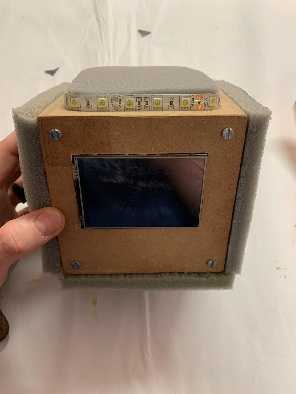
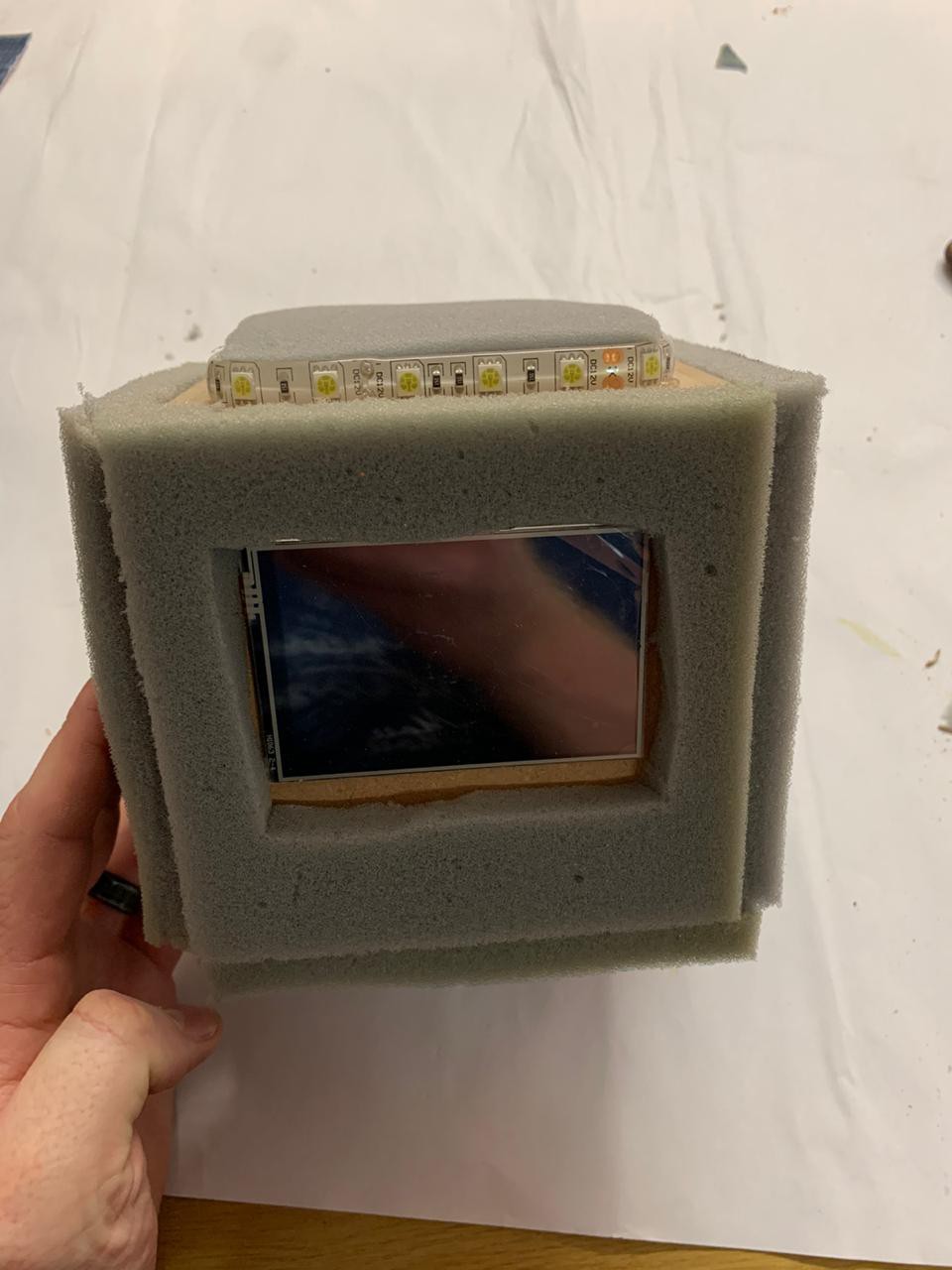
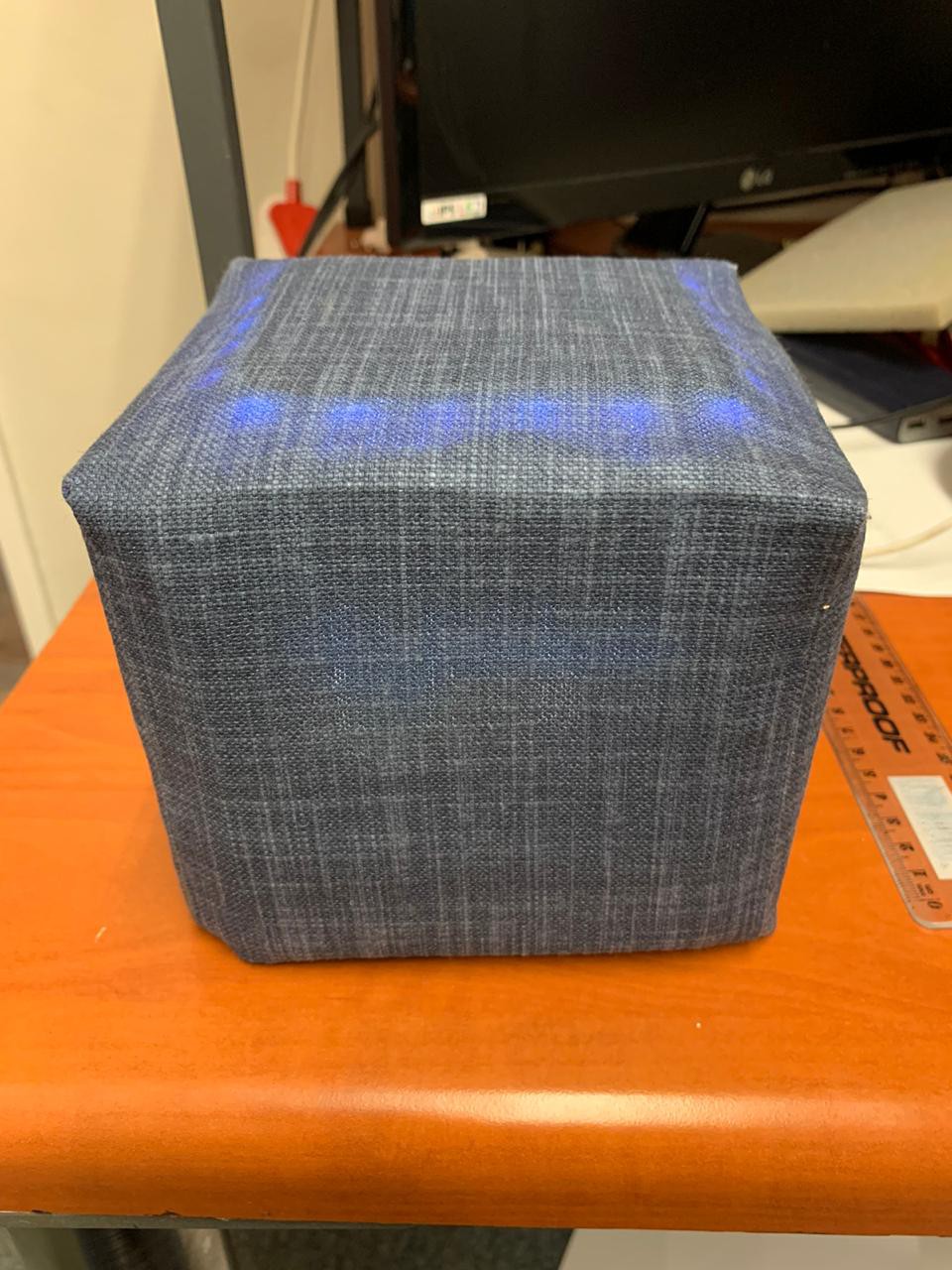
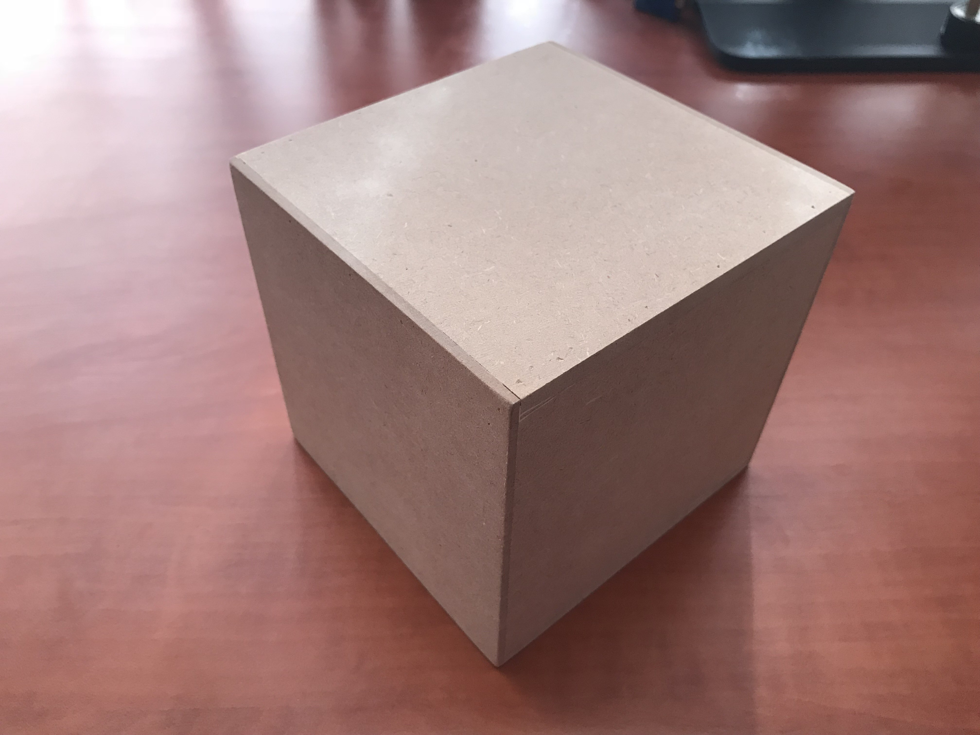
The cube is designed to be an automation platform. In this case a center piece that can be placed on your desk. It will be the control hub for your home automation but also a development platform for testing automation ideas.
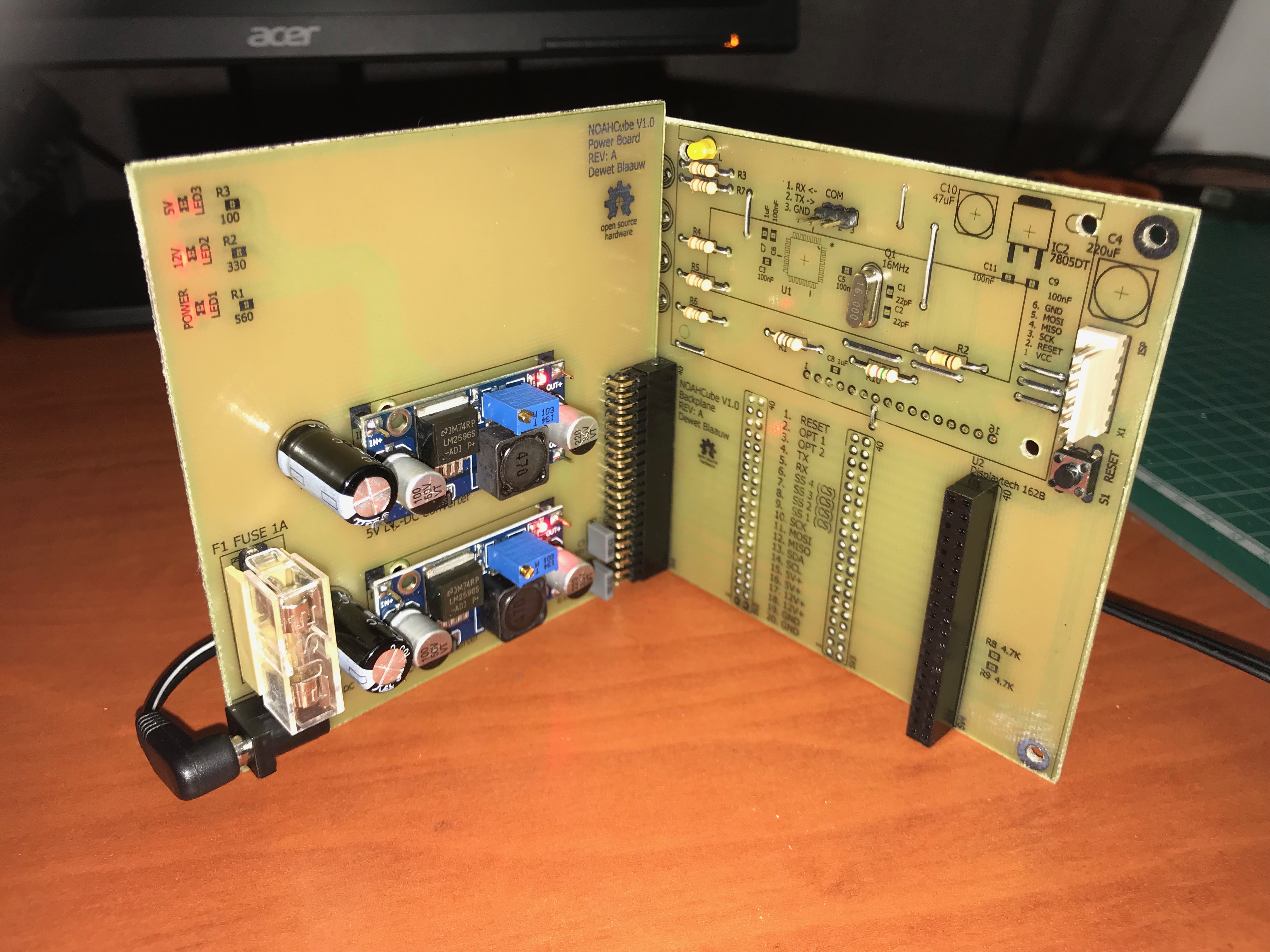
The NOAHCube will be up-gradable, allowing you to slot in a combination of pre-designed add-on cards or, with the complete hardware specs in hand, allow you to design your own. Being completely Open Source I intend this to be something that will help anyone interested in automation.
So far there are 4 add-on cards planned:
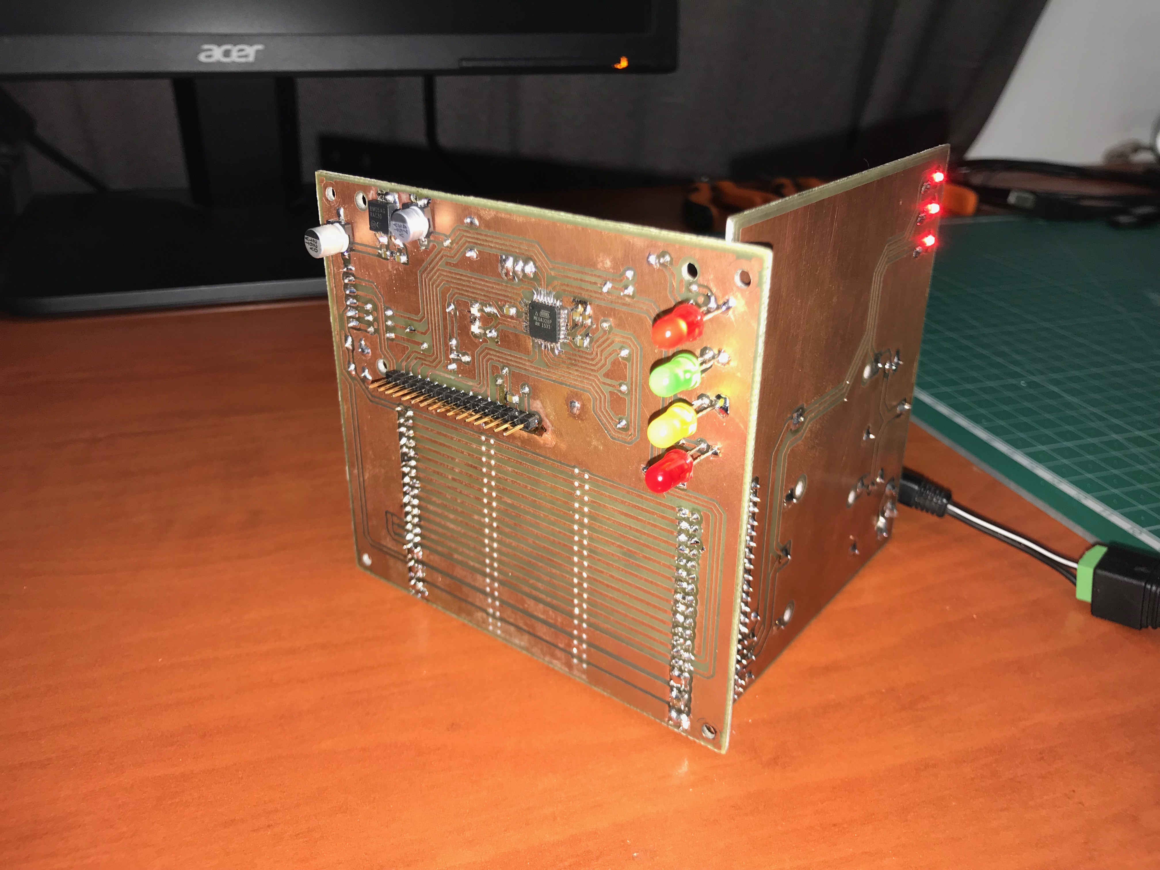
1. POWERCard - This will have all the voltage regulation and control needed to power the cube
2. IOCard - This will come in combinations of 4-Out/4-In, 8-Out and 8-In for Input/Output control
3. RFCard - This will contain all RF goodness, 433Mhz RF radio, WiFI and so on
4. CPUCard - This will contain a beefy CPU as well as an Raspberry PI for completed control.
Why have a card with WiFI and a CPU card with a Raspberry PI that also has WiFi you ask... Well this is so you have the ability to isolate your home/office WiFi with internet access from your sensor WiFi network with no network connection between the two.
 Dylan Brophy
 c.Invent
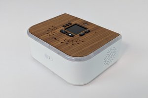
 Mehrdad Majzoobi
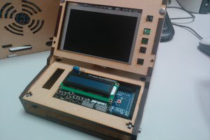
 Craig Hissett