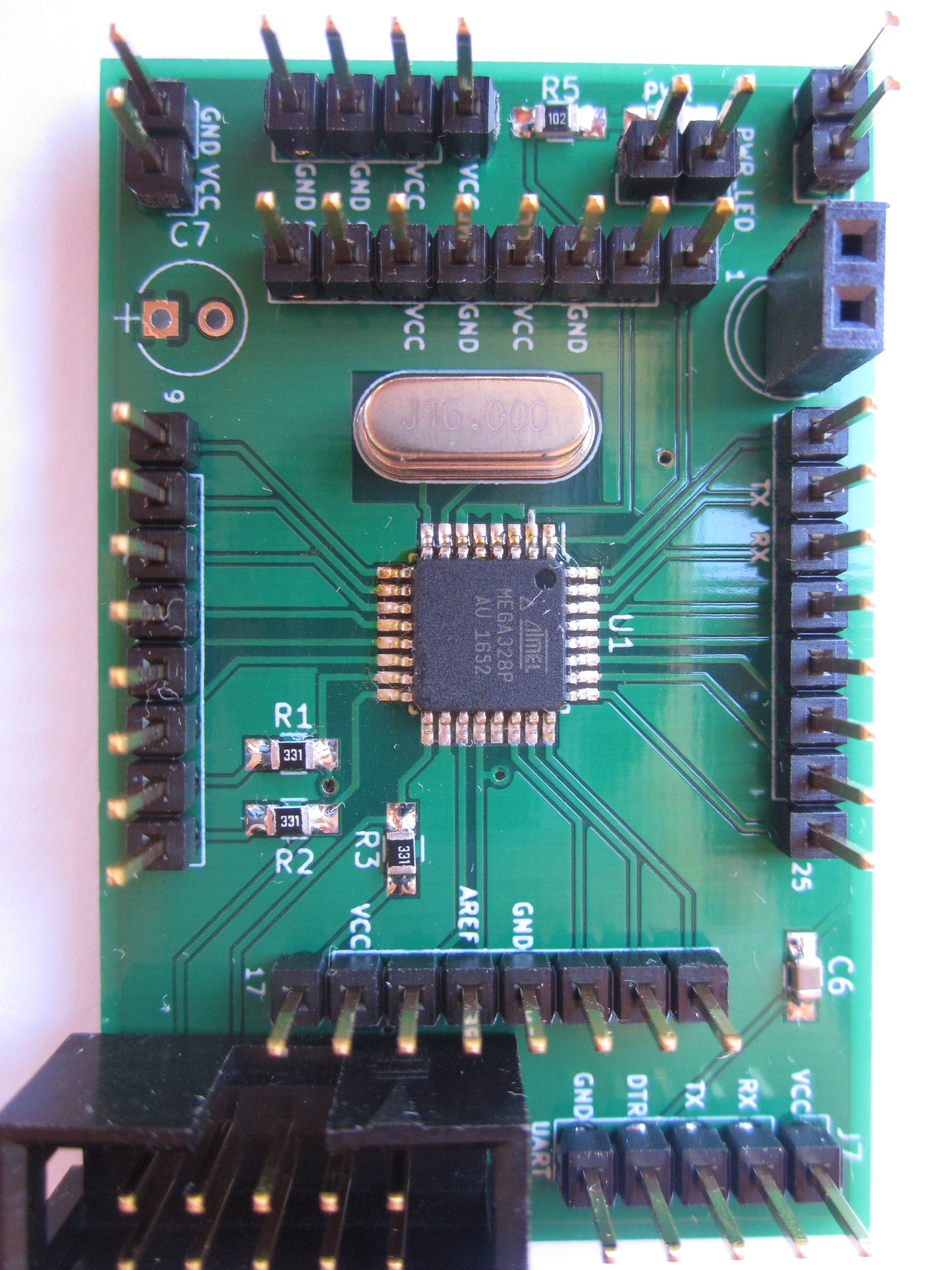
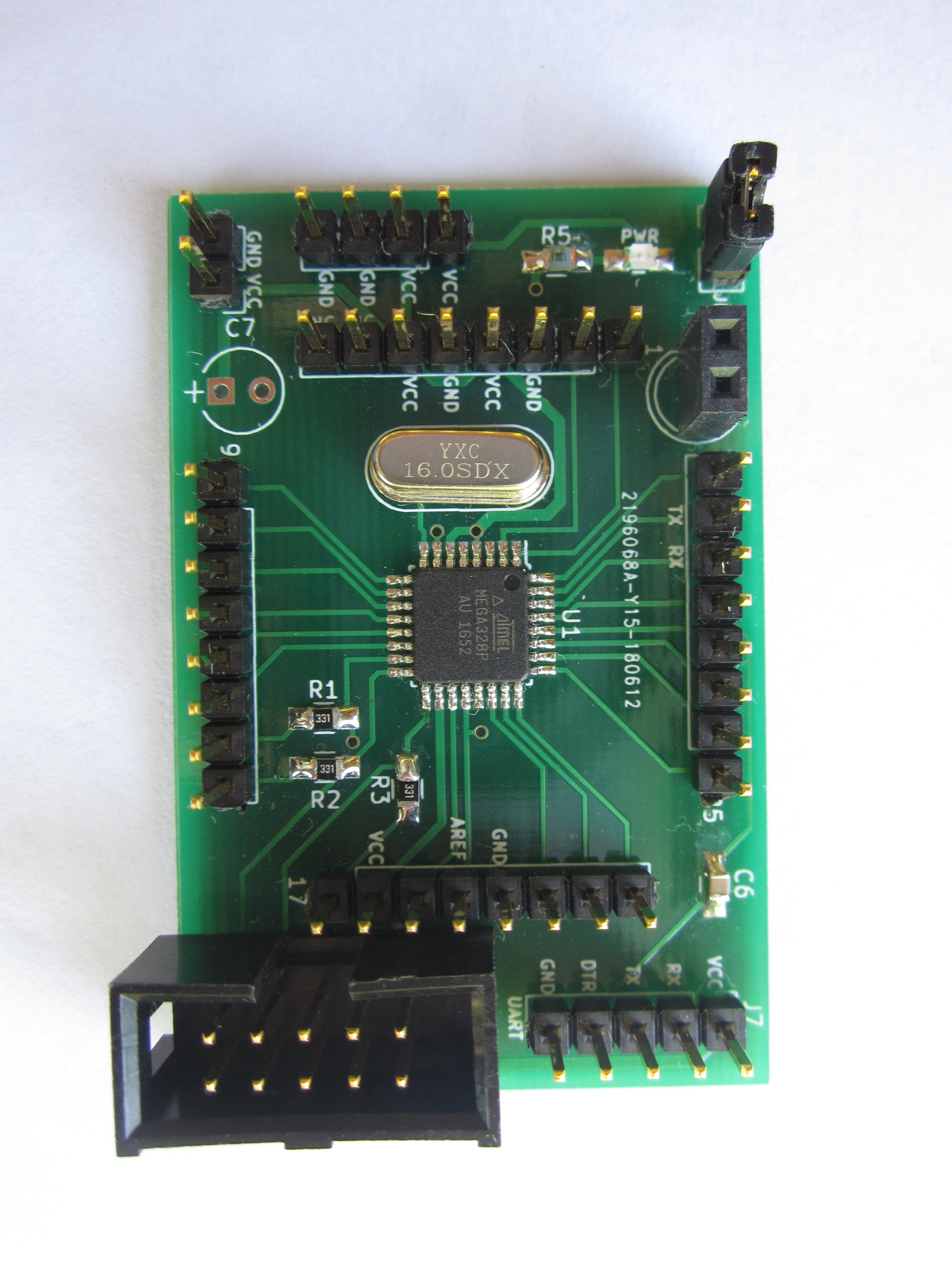
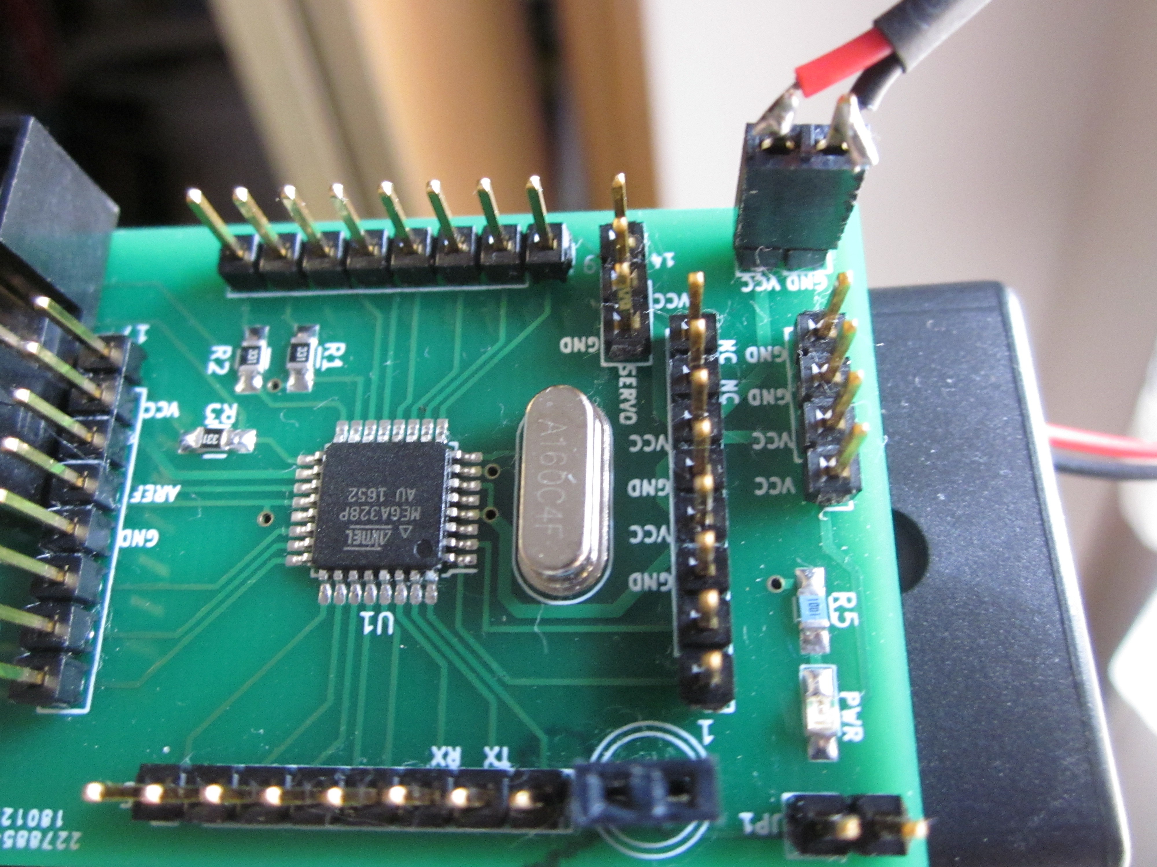
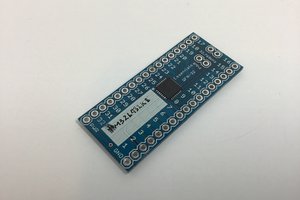
I initially made this board to try out hand soldering a QFP chip (which turned out to be easy when I got the hang of it.) I also wanted to try out a range of clock speeds via crystals.
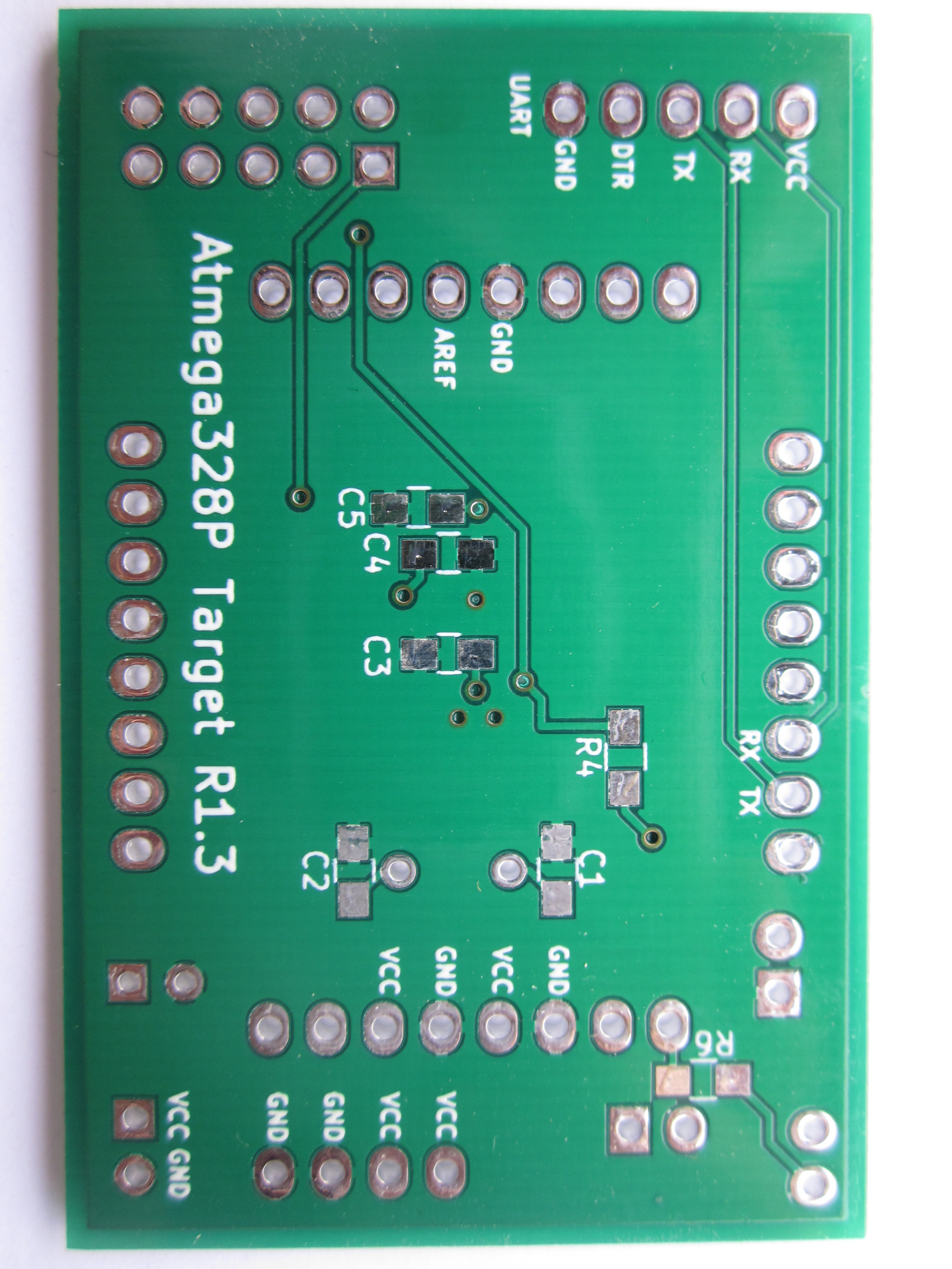
In addition to the board being compatible with Atmega328P(and of course the non-p version of the 328), it's also compatible with the Atmega8A and "mostly" compatible with the Atmega328PB. I say "mostly" for the 328PB because unlike the 328P, pins 3 and 6 are now I/O pins instead of being GND and VCC respectively which means you have to take care to mess with those pins to avoid damaging the MCU. Fortunately, those pins are on a separate port register, Port E.
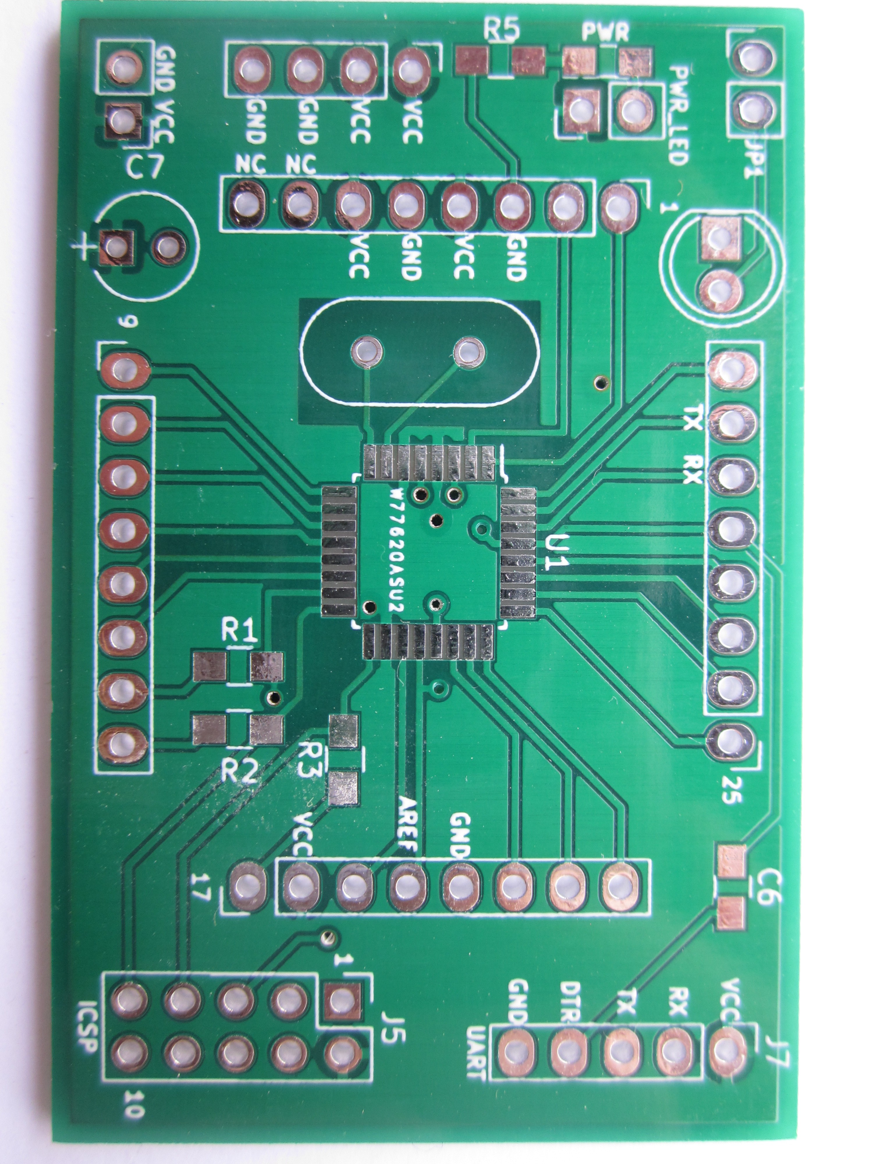
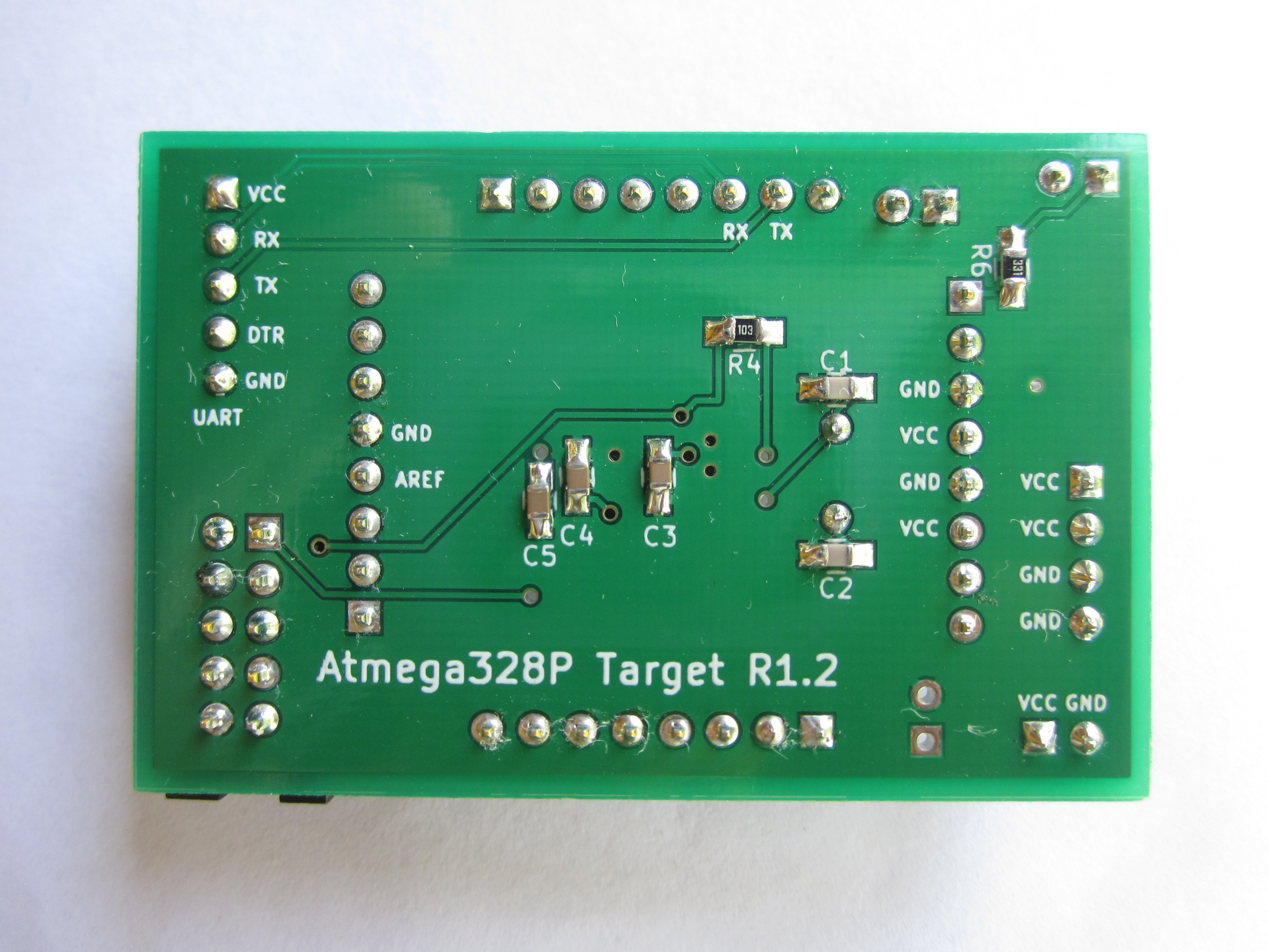
Board features:
10-pin ICSP header
power indicator
UART header (revision 1.2 also has a DTR pin for bootloader friendliness)
A footprint to add an LED(or something else) controllable by pin 1
Revision 1.1 does have a 3 pin servo header, but was removed due to some servos causing the MCU to crash/become unstable
 Ben Lim
 Ian Hanschen
 cyplesma
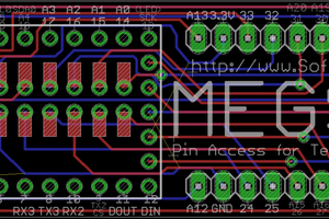
 T. B. Trzepacz