 OzQube
After using these fantastic little ICs in my rock (see my other Hackaday.io project!) I thought that they would be perfect for the square inch challenge.
Taking further inspiration from "The Signal Path" vblog (http://thesignalpath.com/blogs/2013/01/03/tutorial-and-experiments-on-energy-harvesting-ics/) I thought I'd make a tiny 5v (or 3.3v) solar powered power supply, complete with a super capacitor for energy storage. Perfect for wireless sensor networks and other low power IoT devices.
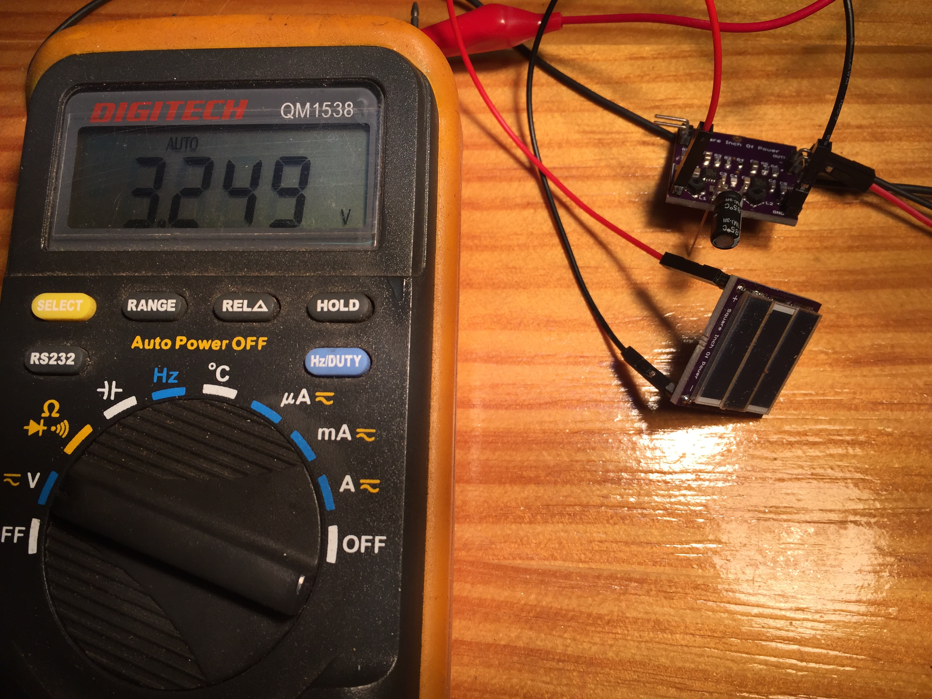
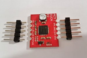
The main board consists of 2 Linear Technology LTC3105 ICs. The first one is connected to the solar cell board (which will also be a square inch board, but I didn't get it sorted in time as an entry). It performs Maximum Power Point Tracking of the solar cells, to extract as much energy as possible. The other great feature of these ICs is the super low startup voltage. They'll startup at under 300mv, boosting the output to the set voltage - in this case, 2.7v - the voltage of the Supercap.
The reason for the second IC is explained in the video, but here's a summary. If I was using a lipo battery, full charge is about 4.2v, and discharged is about 3. There's not much energy left in a lipo below that level, and discharging one lower than that can cause permanent damage. The capacity of a Supercap is based on a complete discharge from its rated voltage down to zero. Now, to get 5v from a 2.7v Supercap, I need a boost converter ( which is what the LTC3105 is). And because of the very low startup voltage, I can use almost all of the energy stored. ( I am soooooo tempted to make an 800% more power available claim here.......but we all know what happens if you do that) . Plus, I wanted to make something that doesn't use lipo batteries, and could be used in a variety of temperatures, including below zero (not that I see any of that here in Australia)
The solar cell board will be able to be stacked directly on top of the power supply. It contains 3 small Ixys solar cells @ 0.5v ea. Connected in series, they should produce 1.5v @ 44mA at their maximum power point. You could attach a larger solar panel, as long as you don't exceed the IC limits and you set the MPPT voltage accordingly


 Jasper Sikken
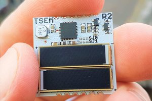
 rawe
rawe
 andrew
The LTC3105 seems to be deprecated ("Not recommended for new designs" according to Farnell)