 JohSchneider
some of the adafruit projects this is inspired by and will be based upon:
the original piggrl: https://learn.adafruit.com/pigrrl-raspberry-pi-gameboy
(its ancestor: https://learn.adafruit.com/game-grrl )
the pocket variant: https://learn.adafruit.com/pocket-pigrrl
and its second iteration: https://learn.adafruit.com/pigrrl-2
Design Goals:
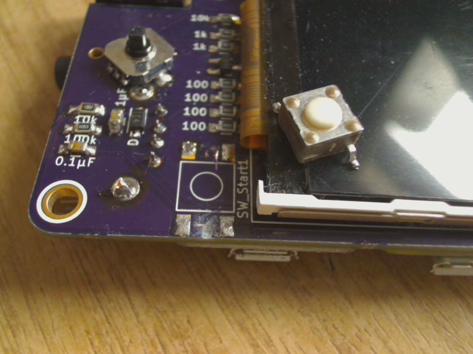
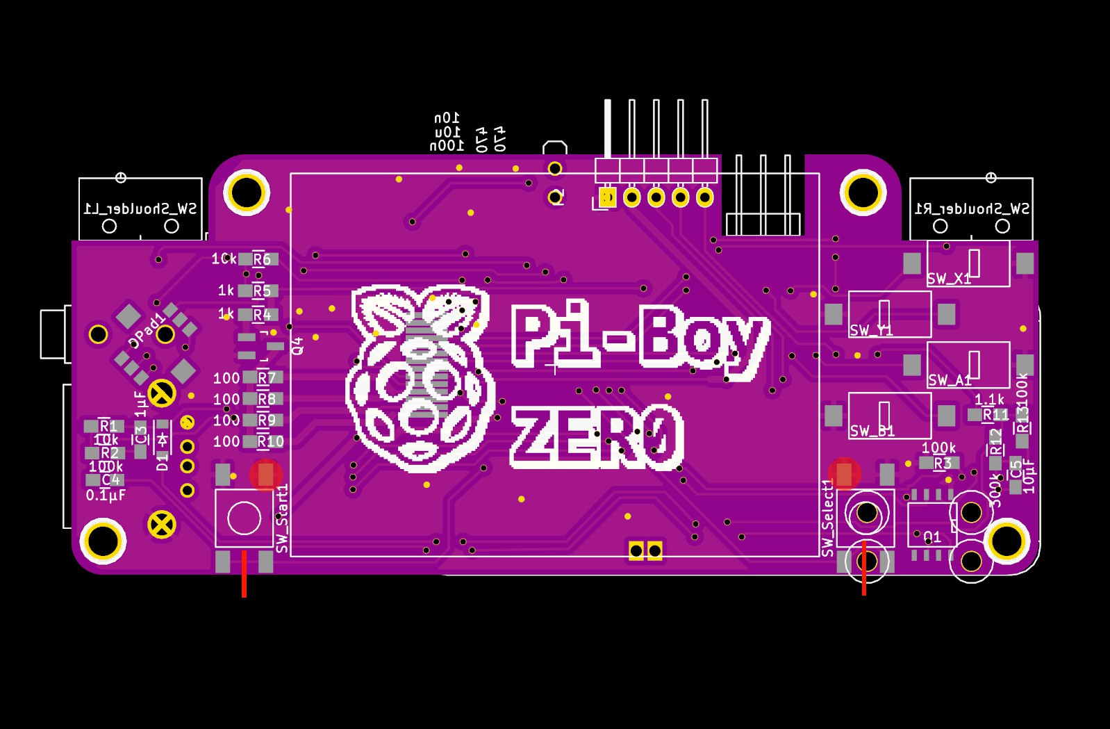
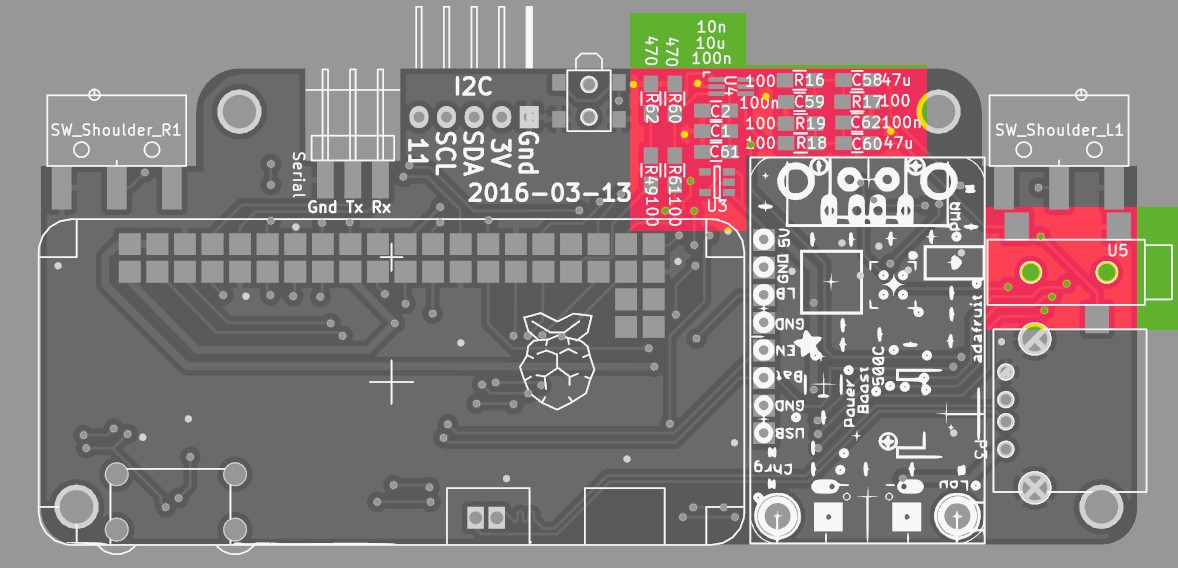
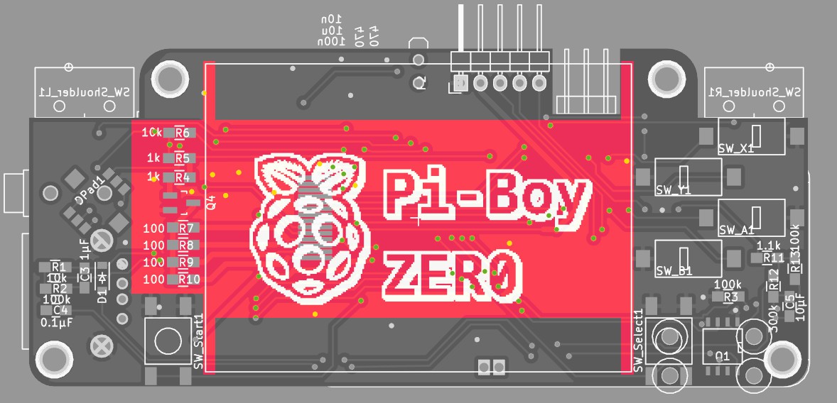
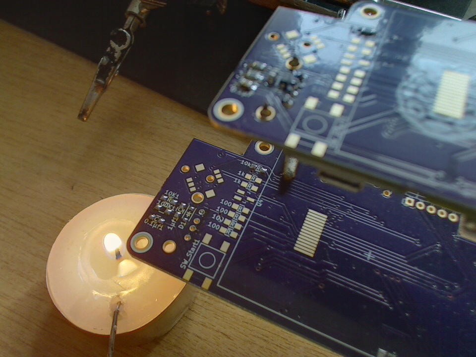
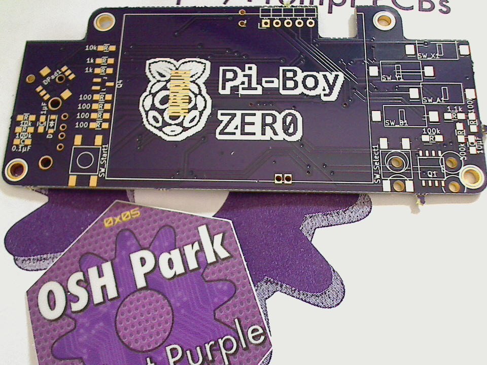
- reduce ratsnest of wires, done with a custom pcb
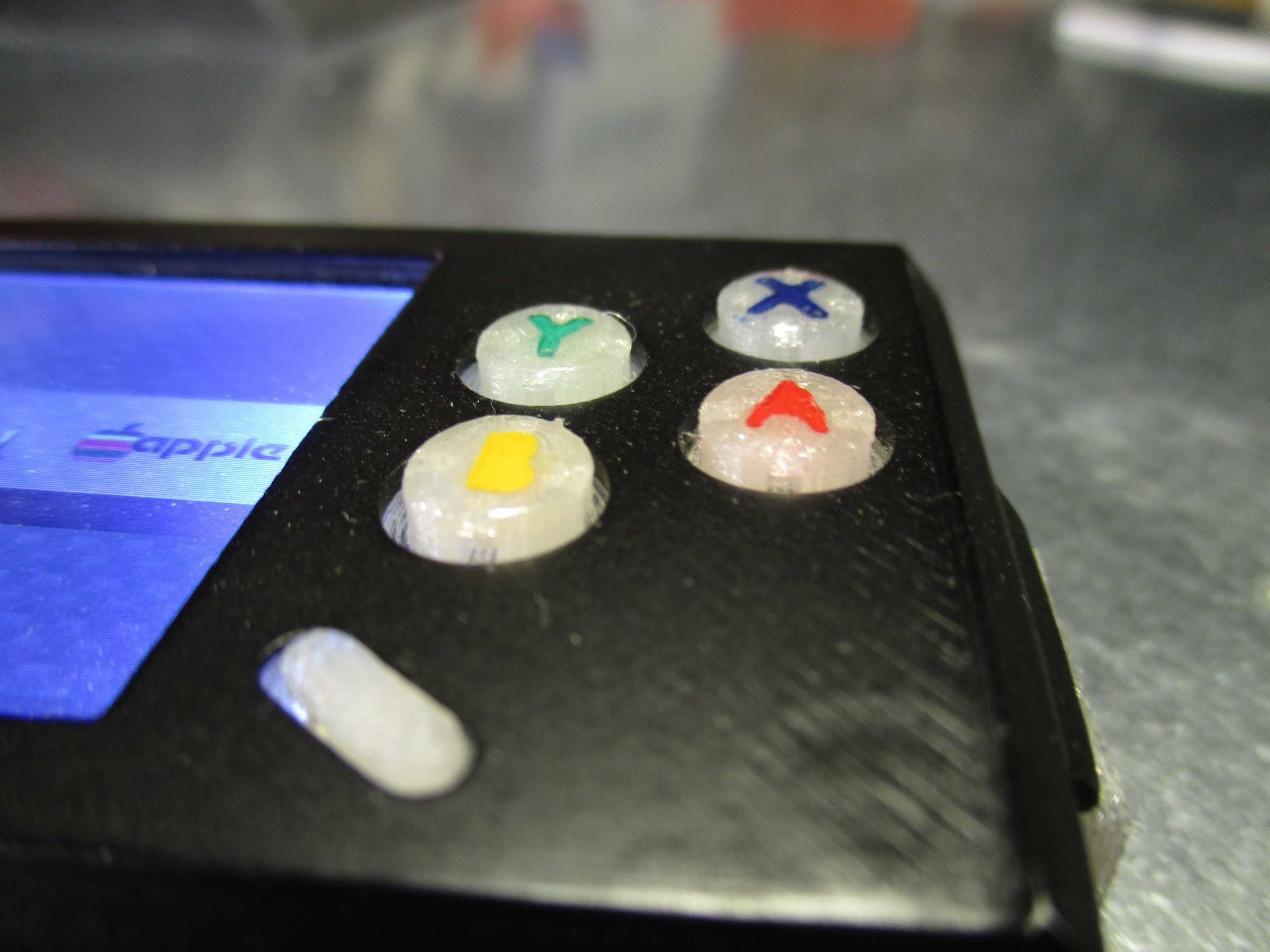
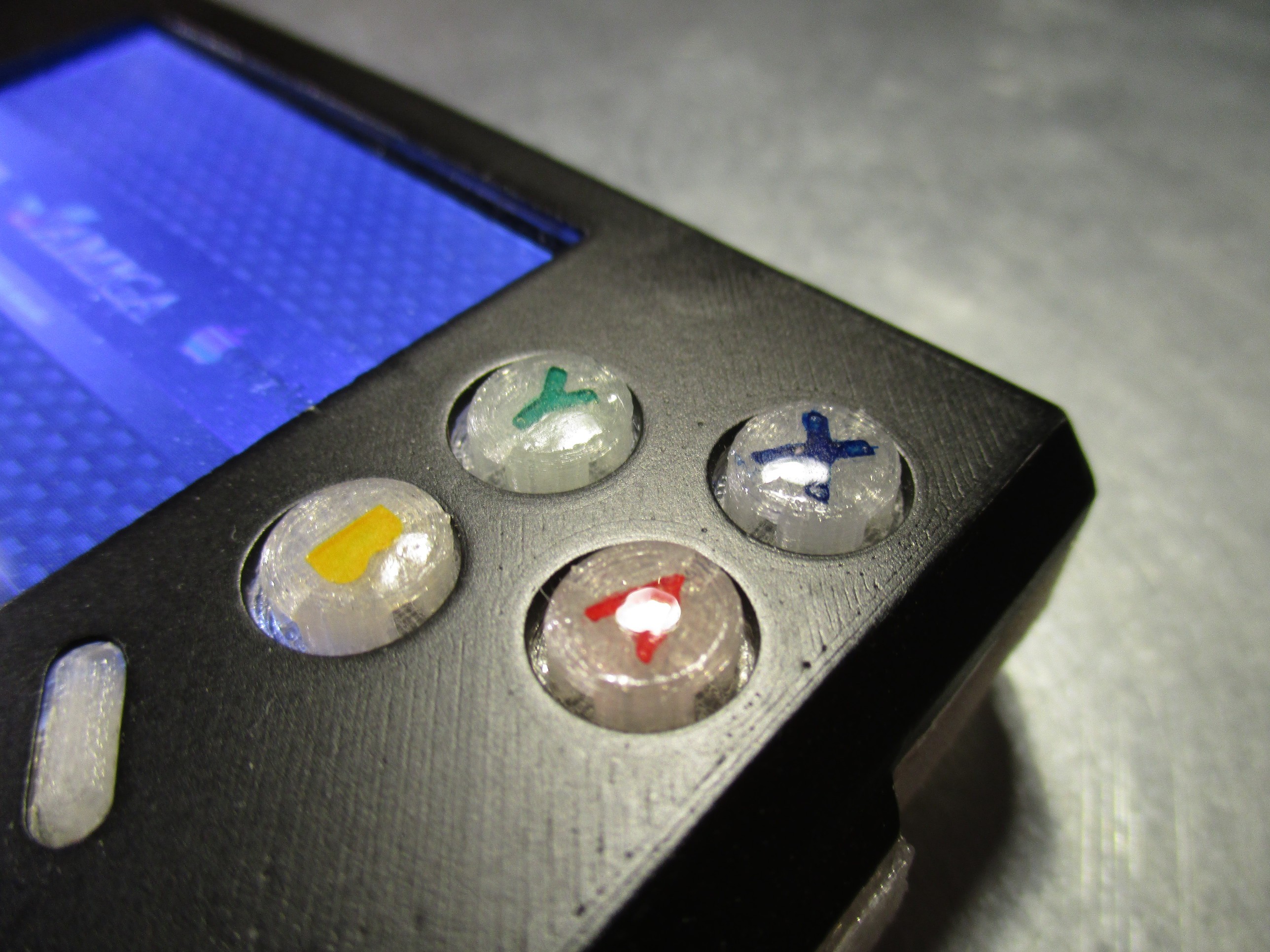
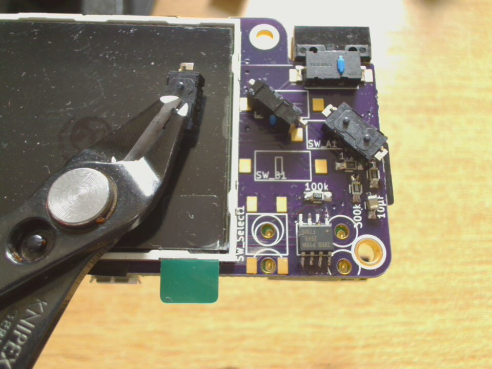
- use good-quality buttons with better "feel" instead of cheaper/harder 6mm tactile switches
- hand-solderable, using 0805 sized smd components and slightly longer pads on the pcb
Features:
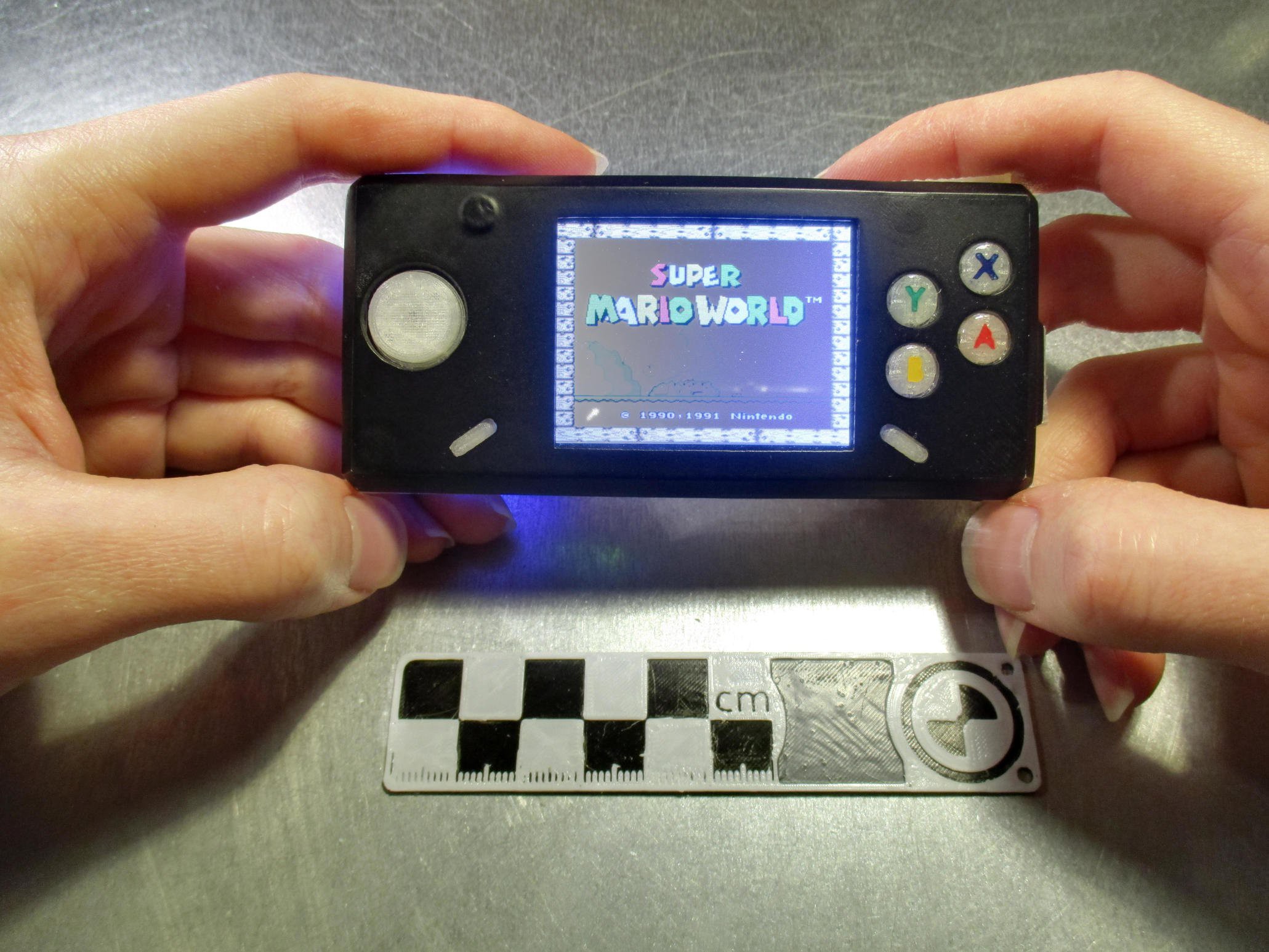
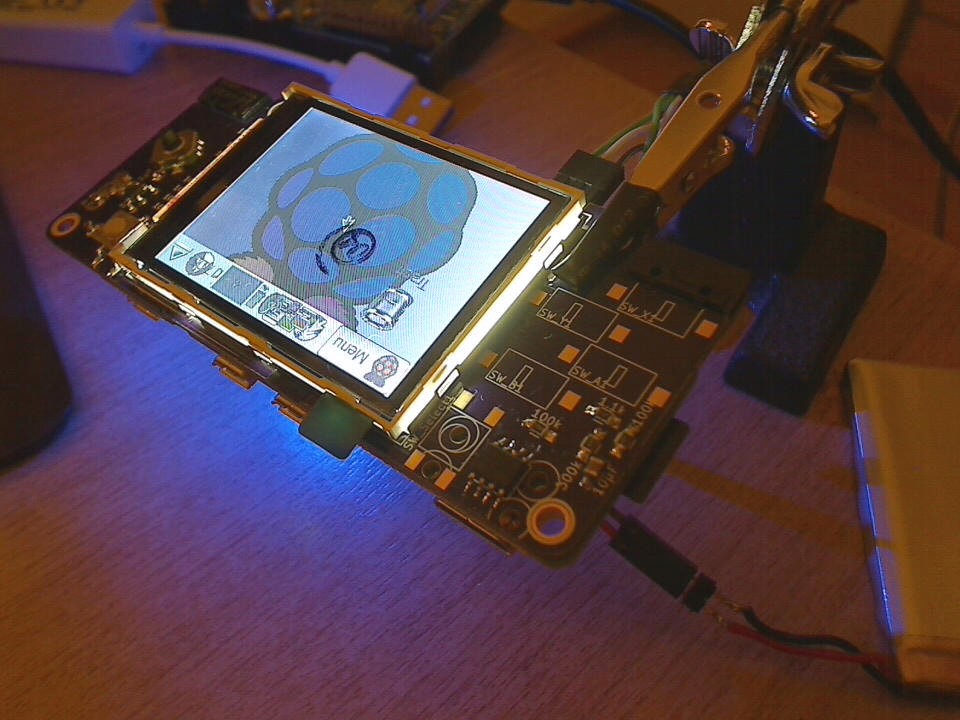
- 2.2" 320x240 display (for comparison, the gameboy-micro had a 2"240×160 display)
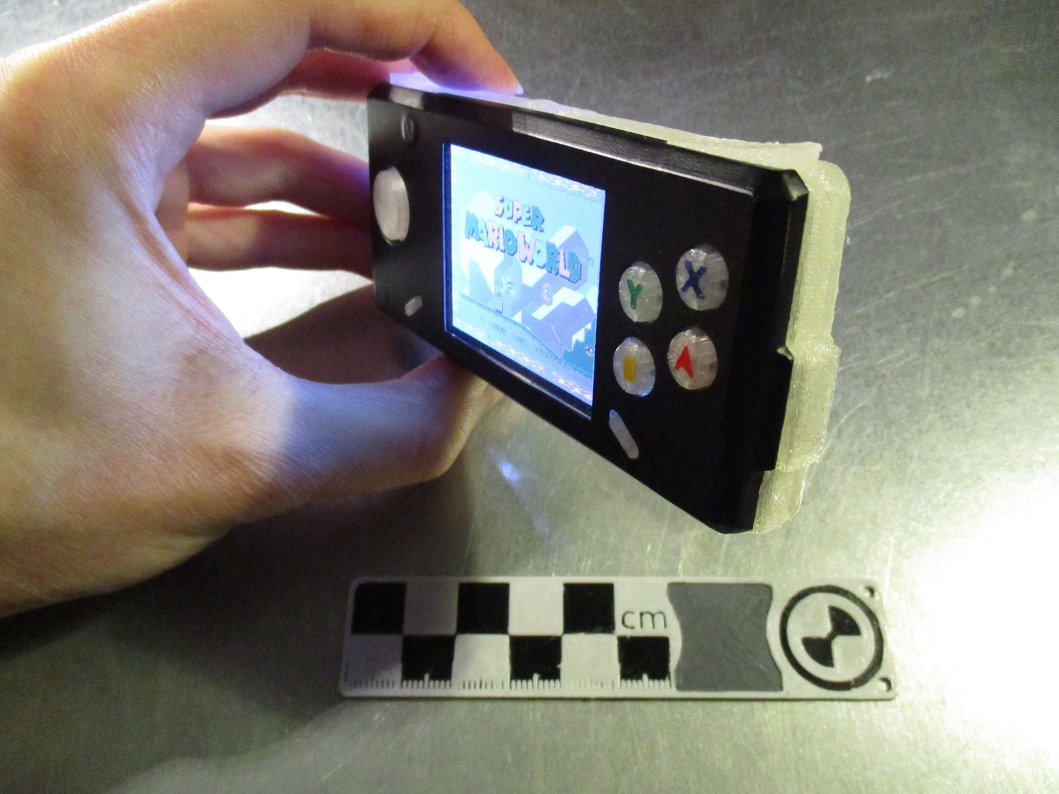
- 3d printable case, with overall size: 48x103x21mm (gameboy-micro: 50x101x17.2 mm)
- power button, for controlled shutdown of the pi (via a pushbutton - push for on/off, hold to force off)
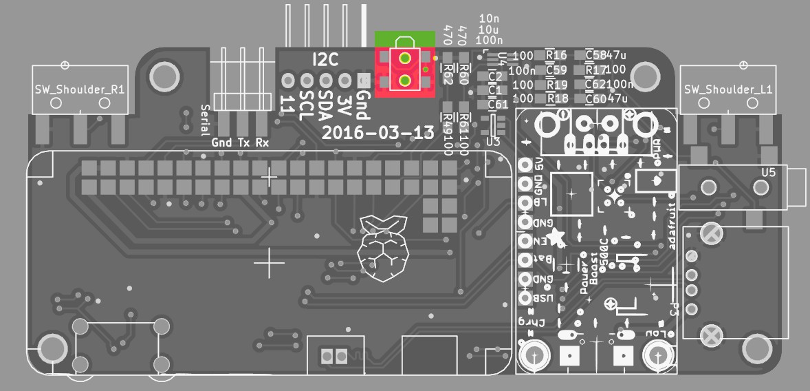
- audio-out (via pwm, like the raspberry 2)
- 1200mAh LiPo battery connected to an adafruit powerboost 500c
- USB-A socket (reusing the connector that comes with the powerboost pcb, connected to raspberry-zero testpads for USB)
- OS: raspbian running emulation-station (and some support daemons to tie in the hardware)
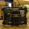
 the way i build them was:
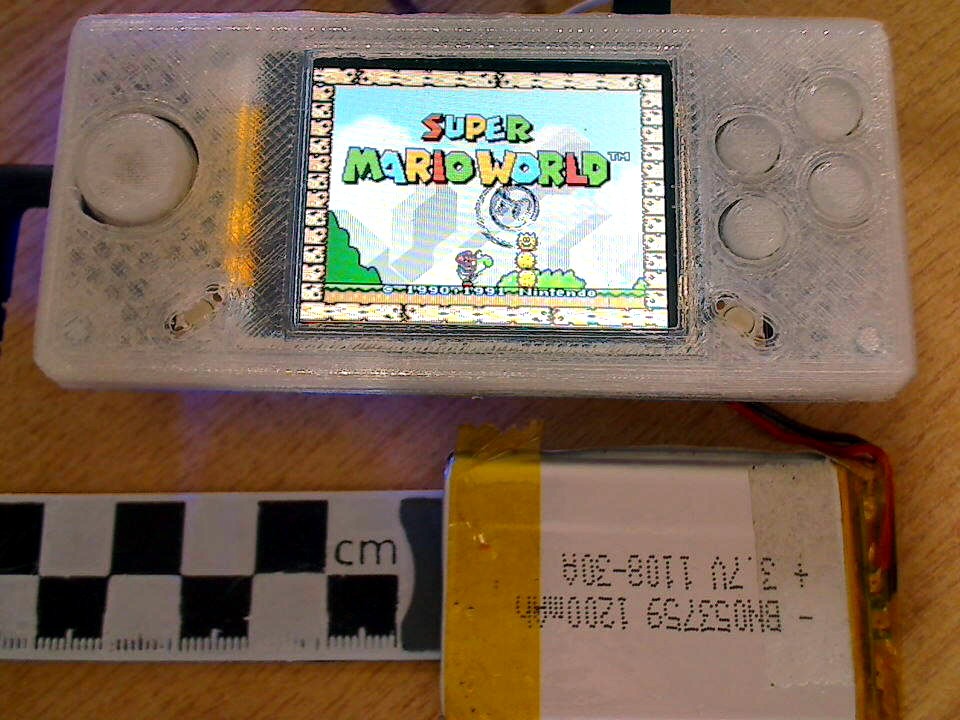
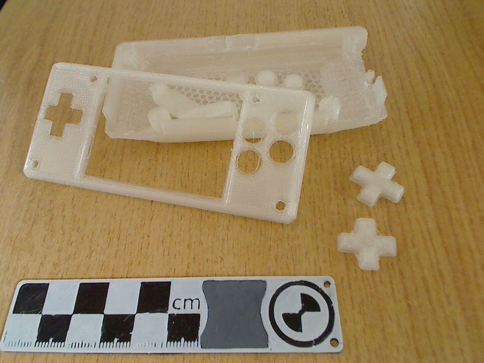
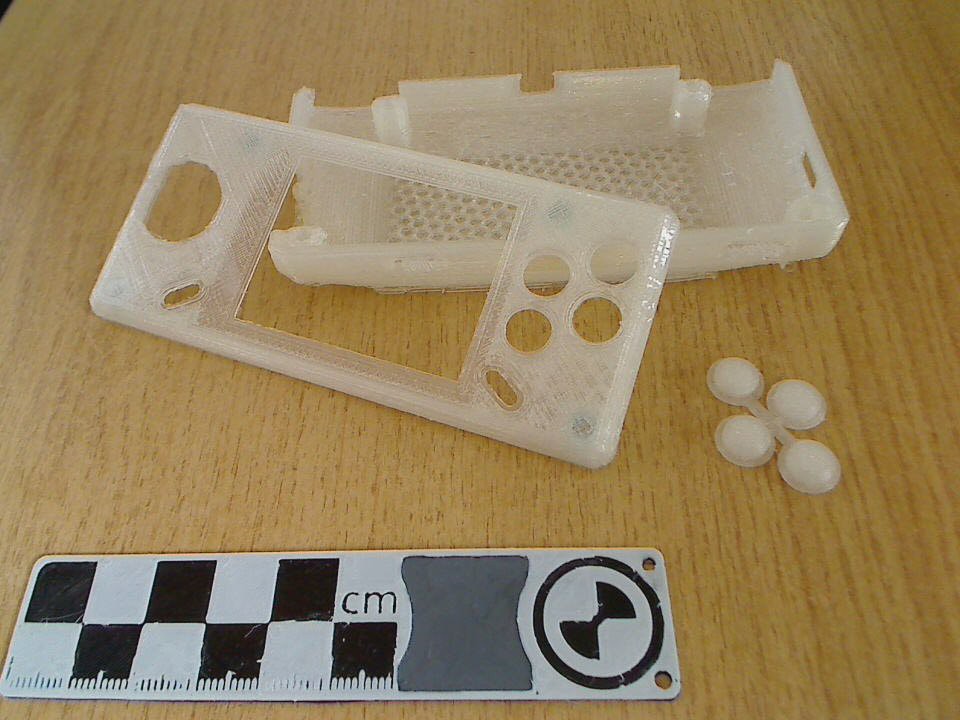
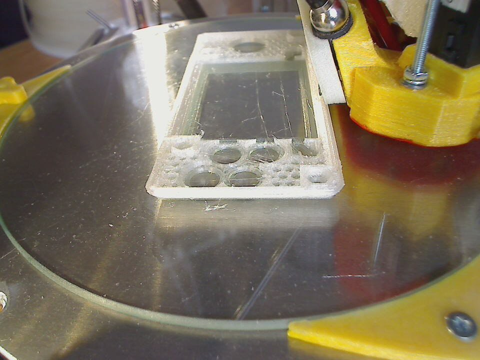
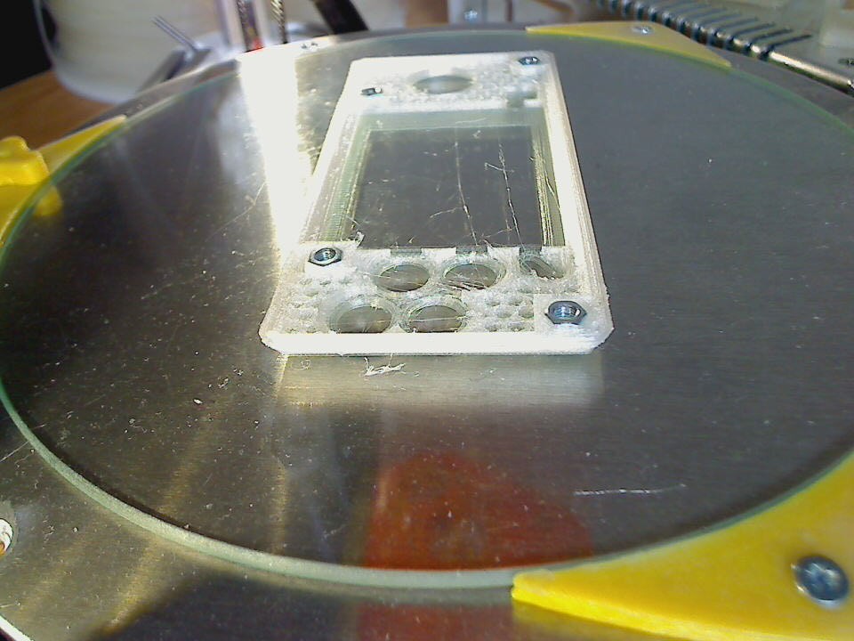
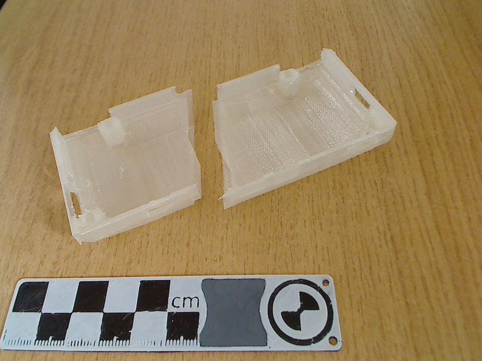 which would be printed standing up:
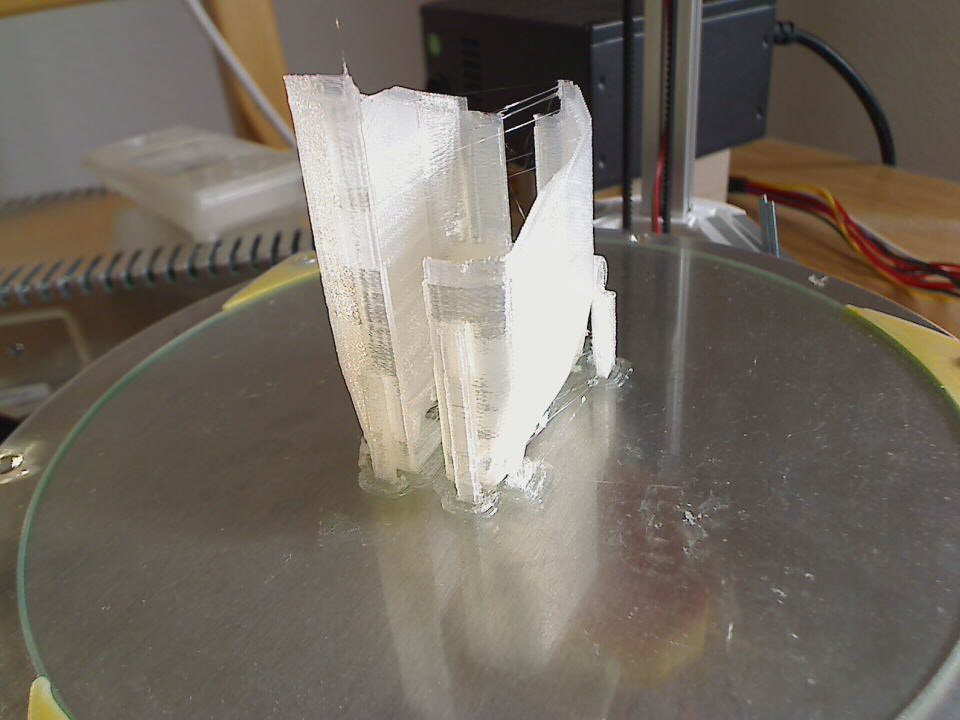


 (upside down, but thats easily fixed in the config)
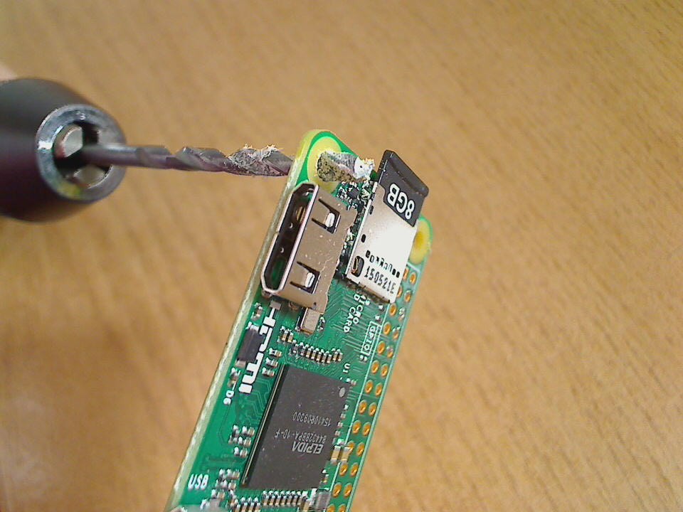


 Kirschner Christoph
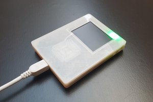
 bram
bram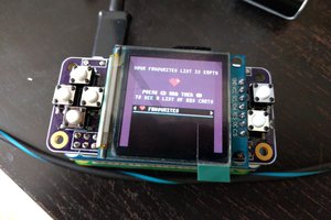
 deʃhipu
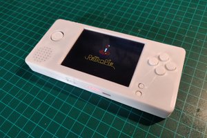
 Pep3175
Hi, found this project and was wondering if it will work with zero 2 because of the missing RCA and reset pins on the pi zero 2.