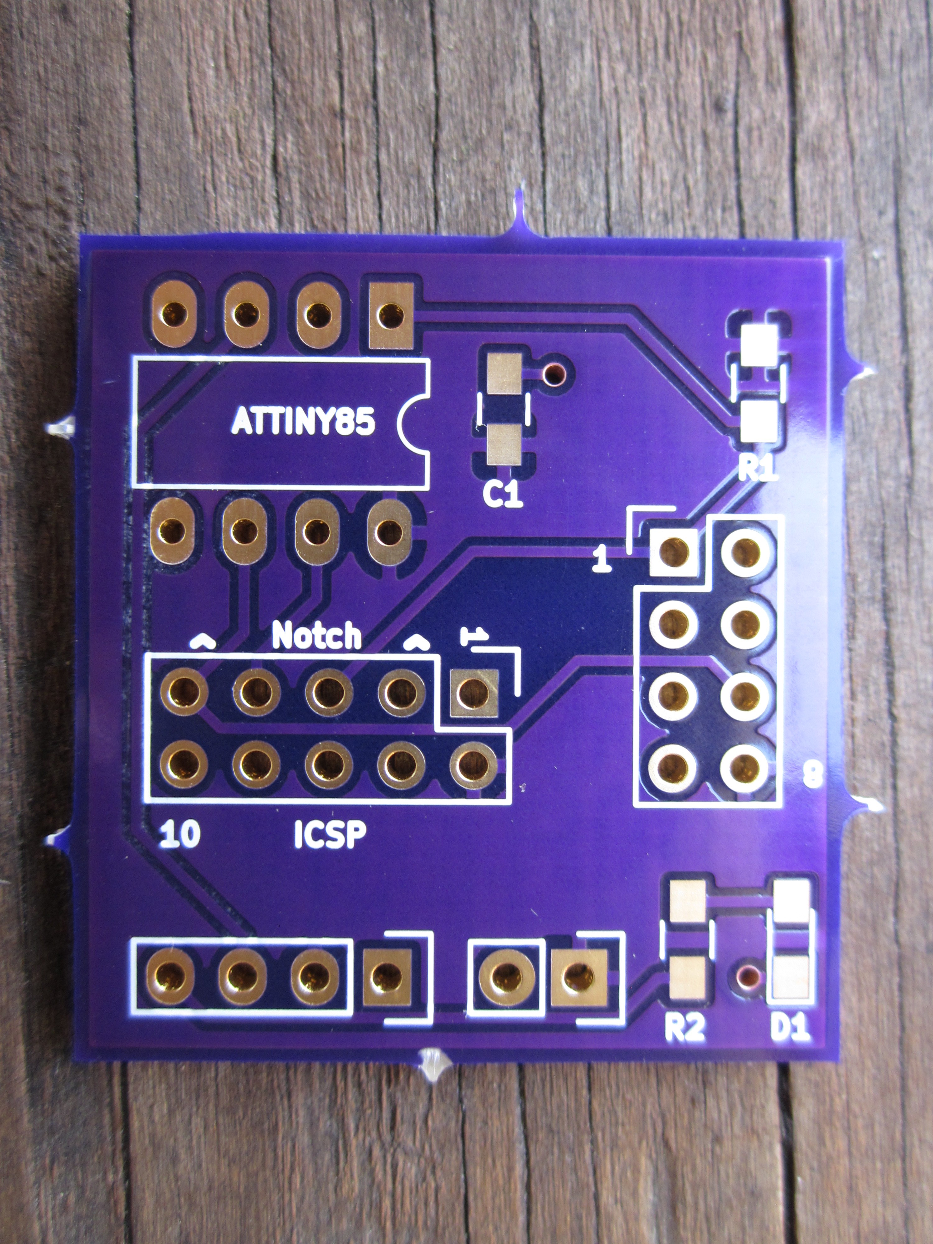
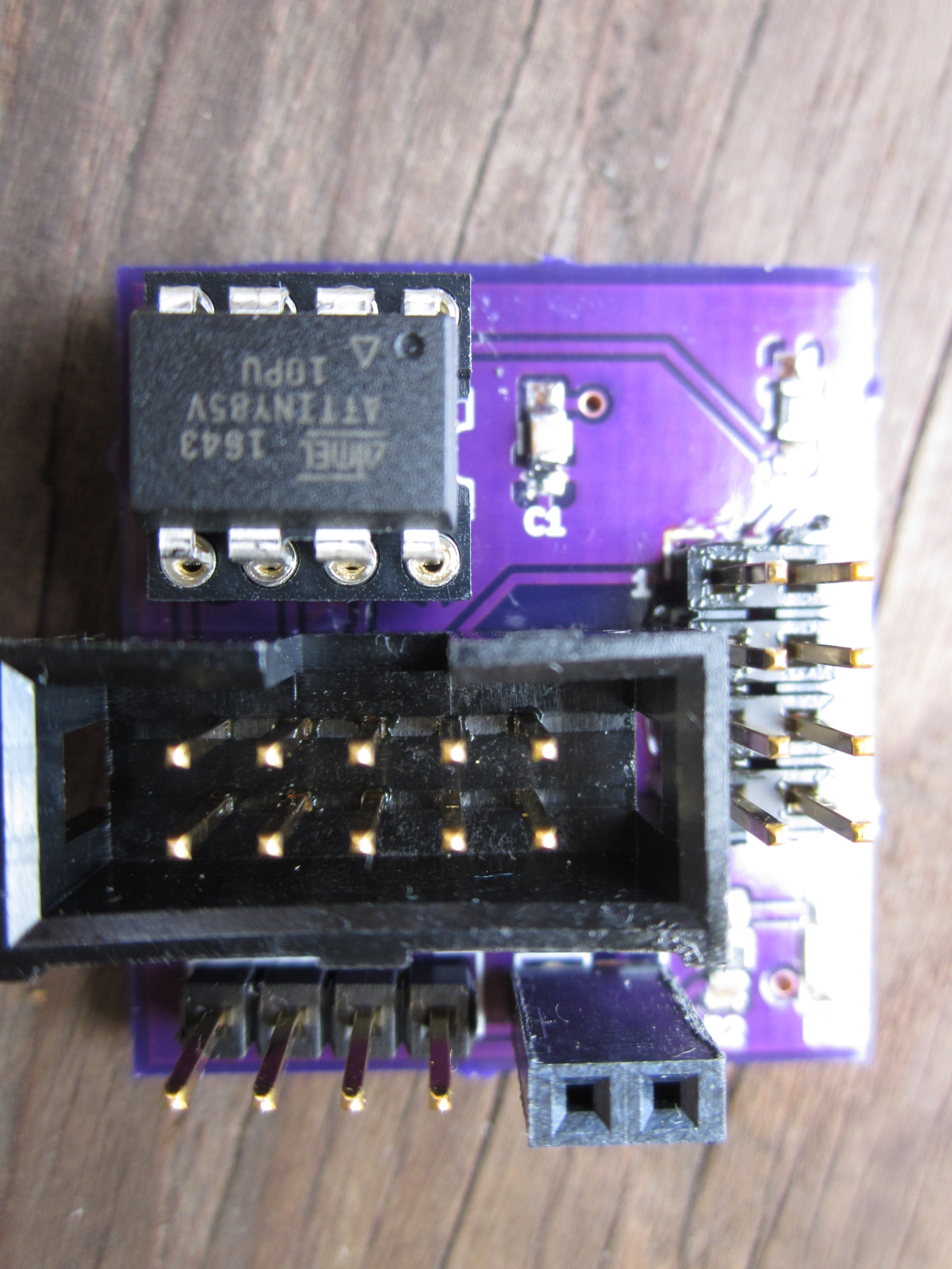
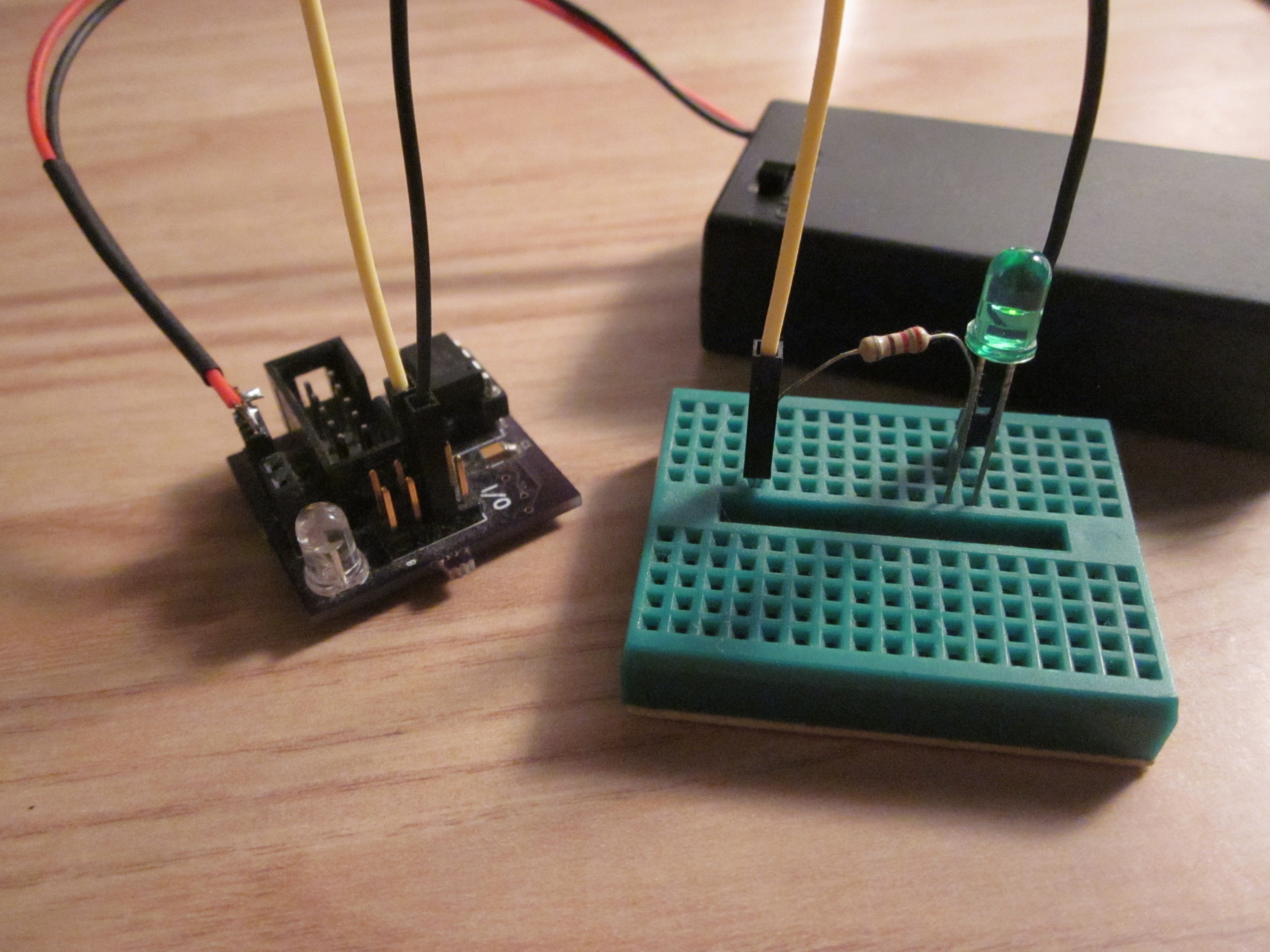
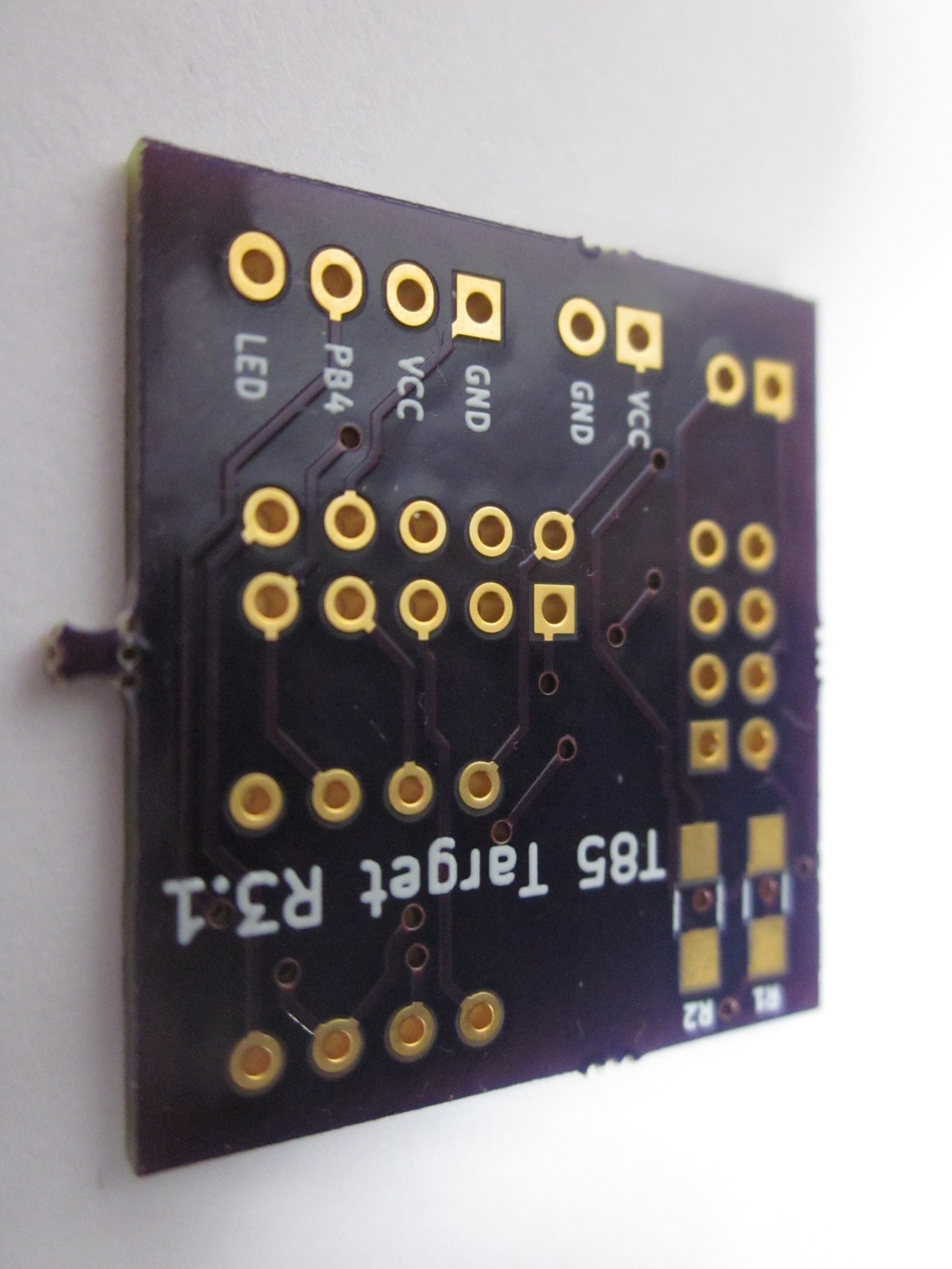
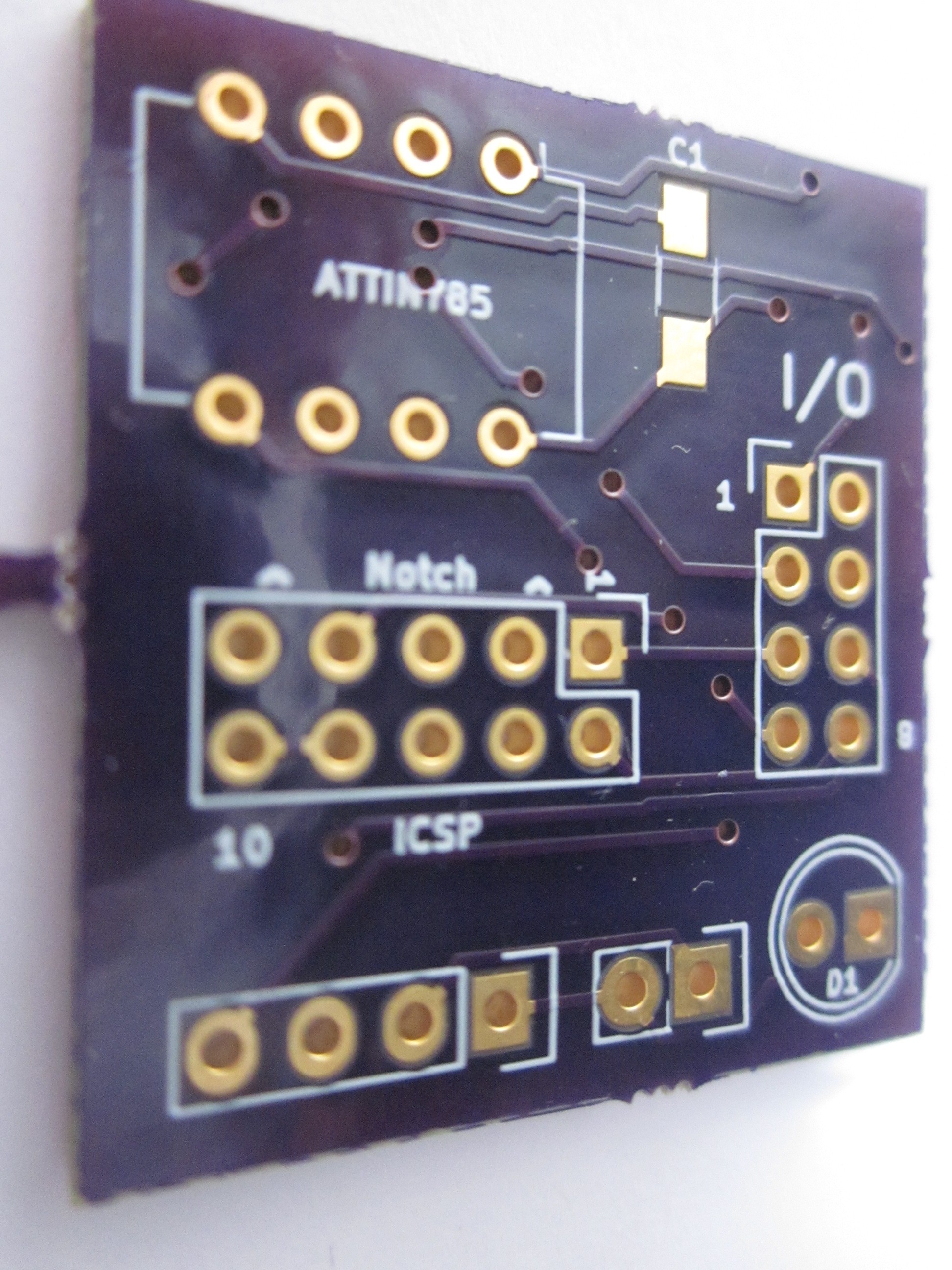
I set out to do this mini project as I was tired of having to plug in individual wires from my USBasp to program the darn thing. I've done a few revisions, with revision 1 and 2 including a power supply but decided against it for the third revision to save on board space. I'm for the most part happy how the third revision came out in comparison to the first two revisions. I switched to surface-mount components for the resistors and capacitors to save a little on space, it looked nicer to me, and to see how easy/hard surface mount components are to work with.
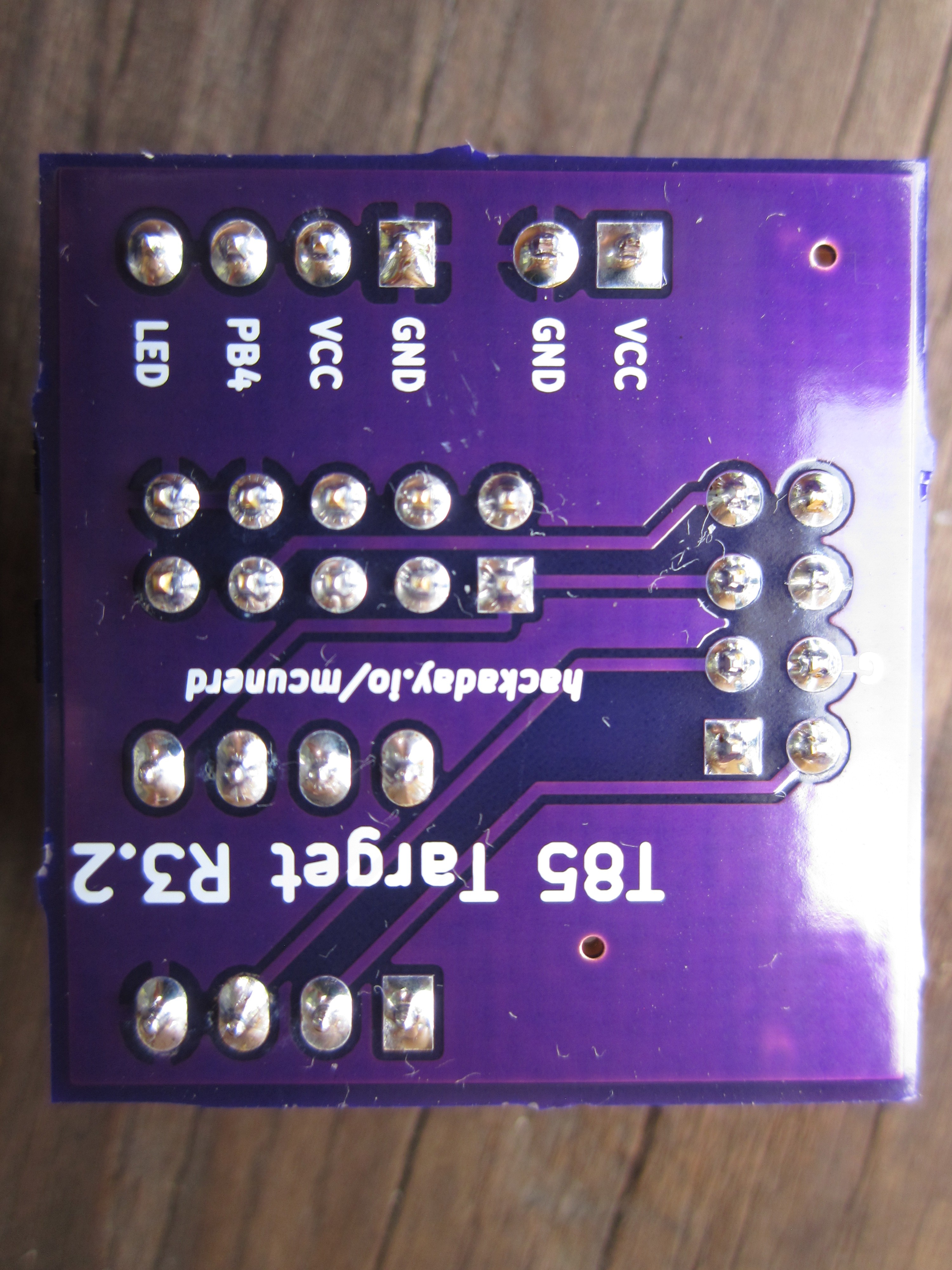
Getting the surface-mount components soldered proved to not be a difficult task. Previous to the third revision, I avoided using surface-mount components in my designs for fear it would be a nightmare to solder. If anything, this project has made me more open to using surface-mount components.
I made a separate board to mount a 5v regulator on with a barrel jack to make use of the many wall warts that I have laying around. I found this to be a more flexible solution as that can be used for powering other circuits. If anyone is interested in that board, I'll be happy to post that micro project.
 deʃhipu
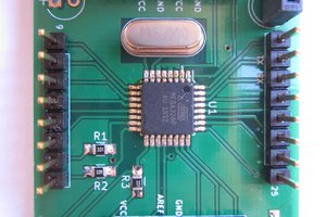
 Carbon