 Electro Dude
-
LED Dot Matrix
05/03/2023 at 15:59 • 0 comments![]()
LED Dot Matrix modules are an excellent way to display information in a compact and visually appealing way. These modules consist of a matrix of LEDs arranged in a grid pattern, which can be used to display graphics, text, and animations. They are widely used in digital signage, scoreboards, and other applications that require dynamic visual displays.
In this tutorial, we will show you how to build a DIY LED Dot Matrix module using the MAX7219 IC. We will cover the basic principles of how these modules work, the components you will need, and the steps involved in building and programming your LED Dot Matrix module.
PCB Designing -
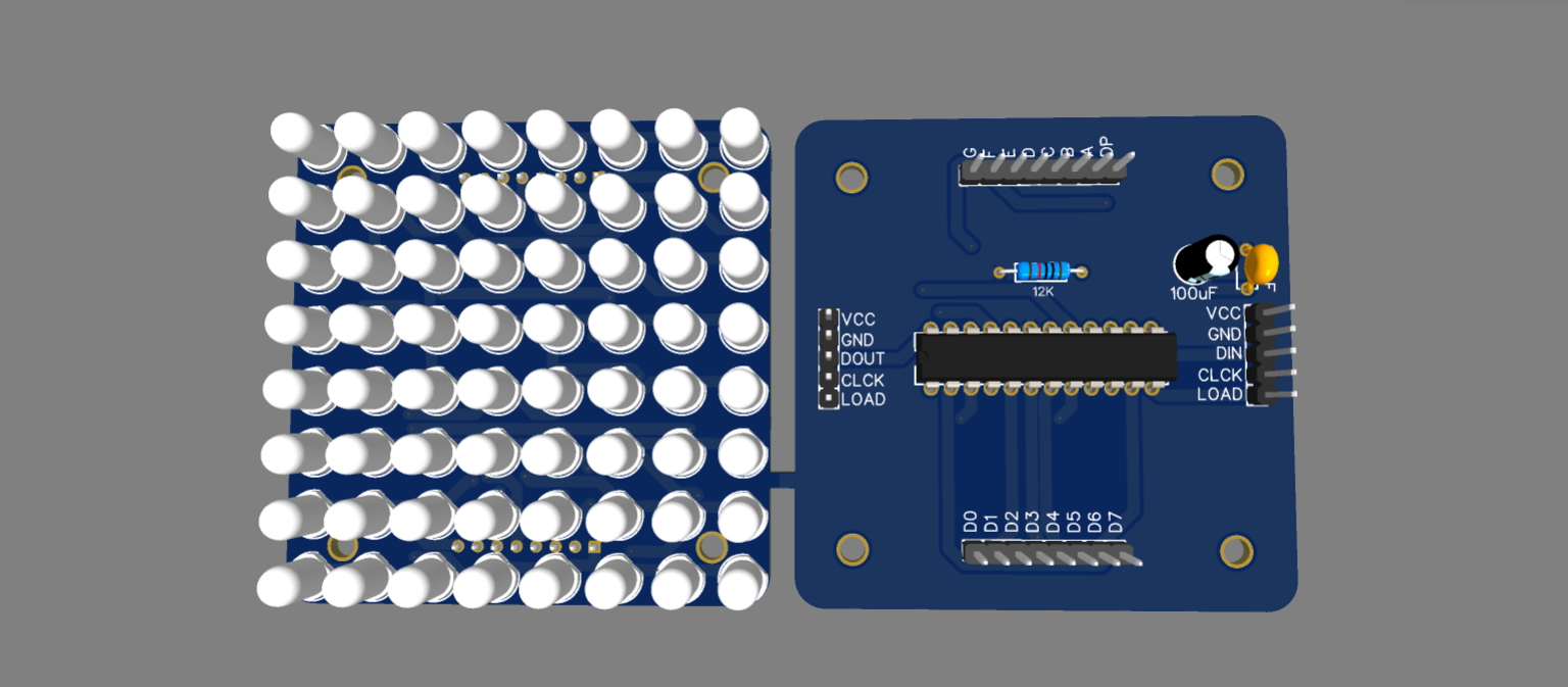
Before we can get started, first of all, We have to design the circuit, after creating the circuit, and then we have to design the PCB. As you can see here I have designed two PCBs one is for an LED MATRIX and the other one is for the driver circuit.Schematic Diagram -
![]()
PCB Layout -
![]()
After Creating the design now it's time to order our PCBs I am going to order my PCBs from “ ALL PCB ” because “All PCB” is the world's fastest PCB manufacturer. After placing the order I received my PCBs within 1 week.
GERBER File for the PCB -
Components Required -
To build This DIY LED Dot Matrix module, you will need the following components:
1. LED Matrix Display
2. MAX7219 IC
3. 10K Resistor
4. 0.1 uF Capacitor
5. 10uF Capacitor
6. Jumper wires
7. Custom PCB
8. Arduino Uno or any other microcontroller board
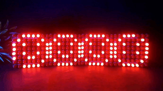
9. 64, 5mm LEDs (Any Colour)
LED Matrix Display
The LED Matrix Display is the core component of the LED Dot Matrix module. It consists of a grid of LEDs that are arranged in rows and columns. The most common size of LED Matrix Display is 8x8, which means it has 64 individual LEDs.MAX7219 IC
The MAX7219 IC is a serially interfaced LED display driver that can control up to 64 LEDs in a matrix format. It simplifies the process of controlling multiple LEDs and enables easy cascading of multiple modules for larger displays.
10K Resistor
The 10K Resistor limits the current flowing through the LED Matrix Display. It is connected in series with the display’s anodes to prevent the LEDs from burning out due to excessive current.
0.1 uF Capacitor
The 0.1 uF Capacitor is used to decouple the power supply from the MAX7219 IC. It helps to reduce noise and ensure the stable operation of the IC.
Jumper Wires
Jumper wires are used to connect our LED DOT MATRIX MODULE with Arduino Nano
Arduino Uno/ Arduino Nnao or any other microcontroller board
The Arduino Uno or any other microcontroller board is used to program the MAX7219 IC and control the LED Matrix Display.Assembling the PCB
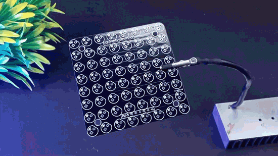
To build the LED Dot Matrix module, follow the steps below:1. As per my design, I have made two layers of PCB so first, we have to solder all the components of the top layer and in our top layer, we have to solder all the 64 LEDs.
![]()
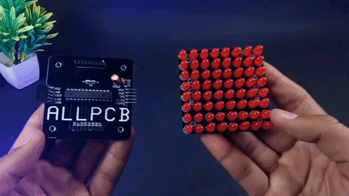
2. After Complet the First Layer Now it’s time for the bottom layer PCB - We need some electronic components like some capacitors, 12k resistors, some male-to-female pin headers, and the most important thing the max7219 driver ic which will drive all the LEDs, Now its time to put all these components into the PCBs and here I don't have 24 pin IC base so I have used three 8 pin IC base. After Soldering all the components simply cut off the legs and then insert the max7219 ic into the ic base.
![]()
The circuit for the LED Dot Matrix module is now complete.
You can now proceed to program the MAX7219 IC using the Arduino...
Read more » -
DIY 7 SEGMENT DISPLAY
09/14/2022 at 07:21 • 0 commentsDIY 7 SEGMENT DISPLAY
INTRODUCTION
In this interesting project we will see how to create a DIY(Do it Yourself) 7 segment which is comparably larger than the traditional 7 segment available in the market.
Before diving into the DIY 7 segment let’s first understand about What is a 7 segment is and how it works.
What is 7 Segment?
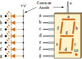
A 7 Segment display is nothing but a combination of LED’s in segments. In a 7 Segment display there are 7 segments named as A,B,C,D,E , F & G.
A typical 7 Segment may be of Common Anode type or of a Common Cathode type.
Common Anode 7 Segment
In a Common Anode 7 Segment all the anode of the segments are common or we can say all the anodes are internally connected. Instead of giving individual power supply(+ve) to all the segments we can give it to the common terminal. To make a segment on we have to give individual Negative supply.
Common Cathode 7 Segment
In a Common Cathode 7 Segment all the cathodes of the segments are common or we can say all the cathodes are internally connected. Instead of giving individual power supply(-ve) to all the segments we can give it to the common terminal. To make a segment on we have to give individual Positive supply.
Design Your Own 7 Segment
Now we will see how you can design your own 7 Segment as per your convenience.
You can design your own PCB as per your requirement. Here we used an online tool to design our PCB.
Here is the 3D view of our Designed PCB.
Ordering PCB from JLCPCB
Ordering PCb from JLCPCB is quite simple and easy.
You just have to add your gerber file (max upto 6 layers) , select layer and add to cart then checkout securely and the sum. That's it no your designed PCB is at your doorstep.
PCB Soldering
Soldering the LEDs on the PCB is quite easy. You need take care of one thing that there should not be any damage while doing.
Now our DIY 7 Segment is ready to use. Here we have designed two different color 7 Segments, you can design as per your requirement.
Now we will see how we can use our DIY 7 Segment with Arduino.
Circuit Diagram
Here we have used a Common Anode 7 Segment so we connect the +5V pin of Arduino with the Common Pin of DIY 7 Segment. And all Other pins have been connected with the digital pins of Arduino. The circuit is also quite simple and easy to make.
Working
When the circuit connection is completed upload a trial code of 7 Segments to the Arduino and Give power supply to the Arduino to make it ON.
Conclusion
In this article we saw how to make a DIY 7 Segment and design our own PCB. Stay tuned for more such projects….
This user joined on 09/14/2022.


 U.S. Water Rockets
 Lutetium
 Daren Schwenke
 Thomas Suarez
 Jaime García
 Alex Rich