Close
0%
0%

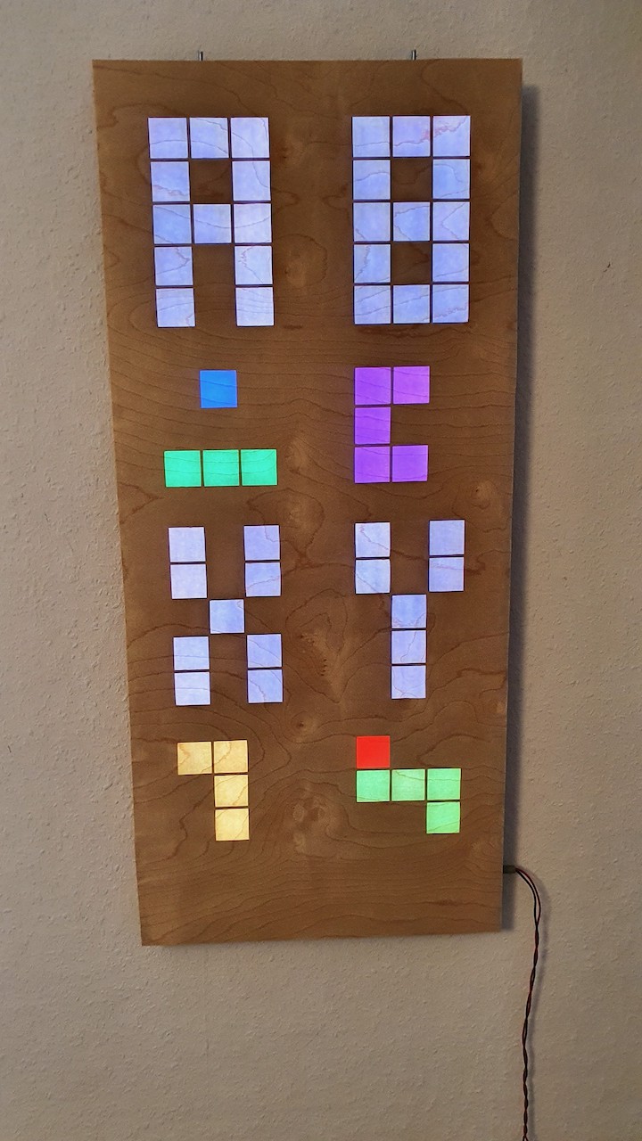
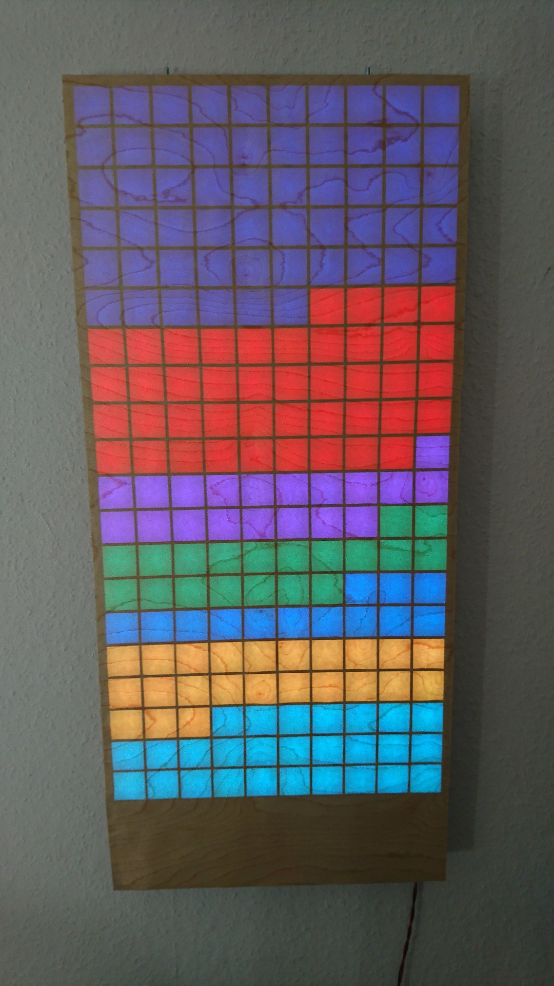
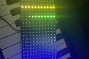
Raspberry Pi Retro Gaming LED Display

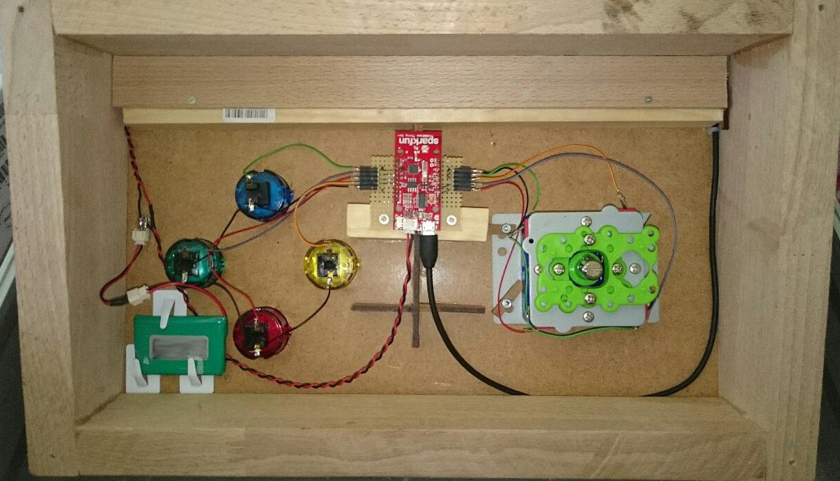
20x10 WS2812 LEDs driven by Raspberry Pi/Arduino to play games like Tetris in the living room

Similar projects worth following
I am building a retro gaming display for my living room to play games like Tetris or Snake with a wireless controller while I am sitting on my sofa. 10 columns of WS2812 LED stripes are integrated in a lasercutted MDF frame, which is covered by a transparent wood veneer. The heart of the system is a Raspberry Pi A+ which is integrated in the MDF frame. This Pi is connected to an Arduino driving the LED stripes. Four 8x8 Matrix displays are combined to a highscore display which is also connected to the Pi via SPI.

The wireless controller is based on an ESP8266-IoT-board, which connects to the Pi over Wi-Fi. A Joystick and four Arcade buttons are used for game controlling. The controller is powered by a LiPo and could be charged by a microUSB connector.

Based on the python_games package coming with Raspbian, all games are written in Python.

This project was inspired by Türtris: https://hackaday.io/project/3708-t

Check the videos on Youtube

ledmatrix.pdf

Schematic

Adobe Portable Document Format - 13.96 kB - 06/12/2016 at 14:51

Preview
Download

matrix_cad.zip

CAD files for MDF matrix

Zip Archive - 306.31 kB - 05/04/2016 at 15:44

Download

  • 1 × Raspberry Pi A+
  • 1 × Arduino Pro Mini
  • 200 × WS2812 LED (stripes 30 LED/m)
  • 34 × Lasercutted MDF
  • 1 × Joystick

View all 7 components

  • Update 2020

    makeTVee02/24/2020 at 17:32 0 comments

    After using the matrix for several years and supporting many other person to realize their own version, it is time to update my matrix based on all the learning from the last years. So now it has the following features:

    • Replacing the old Raspberry Pi A+ with a Pi Zero W 
    • Removing the Arduino board and just driving the WS2812B LEDs with the Pi
    • Using a Bluetooth gamepad instead of the large WiFi-Controller
    • Using inbuilt Bluetooth and WiFi from the Pi
    • Updating all used Python libs to the latest state
    • Adding new features to the software:
    • Auto-connect to the gamepad, reconnect when switched off and on
    • Shutdown the Pi via gamepad
    • Highscore for Tetris and Snake
    • Improved gameplay 
    • Adapt the simulator to the new input device

    So it should be easier now to rebuild the matrix using available components and latest libs. Therefore I wrote an instructable to provide a step-by-step guide to build your own matrix. It is also planned to offer a set with the main components like wood veneer and laser cut parts on Tindie soon. So stay tuned and enjoy making ;-)

  • UART speed issues

    makeTVee01/26/2019 at 05:07 0 comments

    After discussing this issue with several people who want to build their own matrix, I decided to sum up the main points in a project log.

    In the newer versions of the Raspberry Pi with integrated Bluetooth like Pi3B/B+, ZeroW and the new 3A+, the hardware UART is used for the Bluetooth module. The second UART, which is connected to the extension header, is a software UART implementation. This second UART seems to be limited to 250kBaud. You can read more details on this website:

    https://www.raspberrypi.org/documentation/configuration/uart.md

    This project uses 500kBaud for transferring the LED data between Pi and Arduino. I am using an old, non-Bluetooth Pi A+. The only thing, I have changed, was adding this line at the end of the /boot/config.txt :

     init_uart_clock=64000000

    There is an option to change the UART configuration on newer Pis by connecting the hardware UART to the extension header and the software UART to Bluetooth:

    https://blog.adafruit.com/2016/03/07/raspberry-pi-3-uart-speed-workaround/

    I didn't have time to test this, but it looks quite straight forward. Also if there are other solutions, I will update this post.

    Of course, it is also possible to reduce display update timings to reduce the UART speed to 250k. 

  • Data visualization (German parliament)

    makeTVee09/29/2018 at 15:25 0 comments

    I just started to play around with parsing data from internet sources to the matrix. 

    Starting with this page (German parliament seat distribution):

    https://www.bundeswahlleiter.de/bundestagswahlen/2017/ergebnisse/bund-99.html

    and extracting data and colors from the SVG image using this code:

    doc = minidom.parse('diagramm.svg')  # parseString also exists
        style_string = [path.getAttribute('style') for path in doc.getElementsByTagName('path')]
        label_string = [path.getAttribute('aria-labelledby') for path in doc.getElementsByTagName('path')]
        text_string = [text.getAttribute('id') for text in doc.getElementsByTagName('text')]
        data_string = [text for text in doc.getElementsByTagName('text')]
        rgb=[]
        percentage=[]
        index=0
    
        for i in range(0,7):
            rgb.append(style_string[i].split("(")[1].split(")")[0].split(","))
        for i in range(0,text_string.__len__()):
            if text_string[i]==label_string[index]:
                percentage.append(int(round(200*int(data_string[i]._get_childNodes()[0]._get_data().split(": ")[1])/709)))
                if index < label_string.__len__()-1:
                    index=index+1
    
        doc.unlink()
        pix=0

    So after sending this data to the matrix, I got this:

     Nice starting point...

  • Matrix size

    makeTVee04/28/2018 at 13:19 0 comments

    After several questions regarding code adaption for different matrix sizes, python code now has global pixel settings called PIXEL_X and PIXEL_Y.

  • Controller details

    makeTVee03/04/2017 at 07:47 0 comments

    I have uploaded the Arduino sketch of the ESP8266 based controller to Github.

    Wiring is pretty simple, using a Sparkfun Thing and a single cell LiPo.

  • Schematic

    makeTVee06/12/2016 at 14:58 0 comments

    The schematic is now available. There are only three relevant connections:

    1. UART between Pi and Arduino (connected DTR-pin for programming the Arduino firmware from the Pi), with a simple voltage divider for 5V to 3.3V conversion
    2. SPI for the MAX7219 matrix display
    3. Serial connection from Arduino to the WS2812 stripes

  • Android app control

    makeTVee05/26/2016 at 20:40 1 comment

    Instead of the retro controller there is also a small Android app for game control. It provides the same functionality, so no additional controller hardware is needed if you already have an Android device.

    There is a video on Youtube showing the app in action:

  • Github

    makeTVee05/12/2016 at 19:33 0 comments

    Python code and Arduino sketch now on Github. I will add more documentation how to use the code within the next week.

  • Veneer application

    makeTVee05/11/2016 at 19:24 0 comments

    In reply to a comment, I will describe how to apply the veneer paper to the MDF matrix. The veneer I have used, is called Microwood, which is a 0.1 mm veneer with paper backing.

    Before the final full-surface bonding onto the MDF matrix, I did some pre-testing with the glue and the surface preparation of the MDF. To avoid paper curling after the adhesion, I used a solvent based all purpose adhesive (UHU black), which worked as expected. For testing purpose, the black laser cutting edge on the MDF surface was removed with sand paper:

    The following image shows the veneer glued on the MDF sanded off (right) in comparison to the veneer glued on the more or less black MDF. For me, this difference was not enough to polish all the MDF parts and the final result proved me right.

    Because of the paper backing, it is quite easy to apply the veneer and there is no problem with dissolving, although the veneer was rolled up when it arrived.

    If you have any questions, leave a comment.

  • CAD files

    makeTVee05/04/2016 at 15:49 0 comments

    I have now uploaded the DXF files of the MDF matrix. I have used 3mm MDF. The next version will be a combination of MDF and cardboard to save some cost.

View all 13 project logs

Enjoy this project?

Share

Discussions

ourharlequin wrote 02/28/2019 at 08:03 point

Hello again. I already do this. It works on my 16x32 matrix. Thanks for Yours answers. It helps every time. Also i have a questions:))))))

1. How to move clock and icons to the center of the matrix? It's displays clock and icons in the upper corner like if i use 10x20 matrix.

2. How to make a speed of blocks in tetris game faster? 

3. How to make a speed of snake in snake game faster? 

4. How to make a speed of ball in pong game faster? 

5. How to fix a ghost right wall in pong game? The ball is repelled from the invisible wall to the right. It's displays game like if i use 10x32 matrix.

  Are you sure? yes | no

makeTVee wrote 03/16/2019 at 14:39 point

Sorry for the late answer!

1. You have to change the drawNumber calls in the drawClock function. drawNumber gets an offset for x and y as a parameter, so please adapt this clues to your matrix.

2. Please change this values at the beginning of the python code:
MOVESIDEWAYSFREQ = 0.15
MOVEDOWNFREQ = 0.15
FALLING_SPEED = 0.8

3. Change the time.sleep(.15) at the end of runsnakeGame()

4. Change the time.sleep(.1) at the end of runpongGame()

5. Did you changed the PIXEL_X and PIXEL_Y?

  Are you sure? yes | no

ourharlequin wrote 03/18/2019 at 07:35 point

Thanks for Yours answer. I alredy find the option speed of tetris and changed it. I will try fix snake and pong speed. I changed PIXEL_X to 16 and PIXEL_Y to 32 in python and arduino codes. Here is my first public video with Youe project: https://goo.gl/H4hxR6

P.S. I have an idea to make an instruction how i build a changed Yours project for giant matrix and diferent controllers.

  Are you sure? yes | no

makeTVee wrote 03/18/2019 at 19:02 point

I found the bug in pong:

Please search for (ballx<9) and replace it with (ballx<PIXEL_X-1)

Thank you for the video, it looks absolutely fantastic, would be great to see an instruction. If you want you can also join this project on hackaday, I have many ideas how to change the python code for additional pixels.

  Are you sure? yes | no

ourharlequin wrote 03/19/2019 at 07:06 point

Tomorrow I will be in garage and try all! I have idea to port maze generator. Hope, that I can do this;)

  Are you sure? yes | no

andersflex69 wrote 02/27/2019 at 12:36 point

Hi, I hope you have a great day.

I try to use your code on a 22*87 matrix (1914 WS2812B). Everything works as expected as long as I don't exceed 14*20.

Even if I change the buffer size and lower the speed of the UART  nothing appared on the matrix.

Maybe you have an idea for helping me?


Best regards, Anderson69s

  Are you sure? yes | no

makeTVee wrote 02/27/2019 at 16:46 point

Which Arduino do you use? Could be an SRAM issue. You can also try to decrease the update rate in the Python code to decrease UART load.  It is quite a lot of data to transfer!

  Are you sure? yes | no

ourharlequin wrote 01/05/2019 at 09:18 point

Thank You. I will try this! Really want to test yours project on my matrix;) https://www.instagram.com/p/Br7DGNKDfPY/

  Are you sure? yes | no

ourharlequin wrote 01/03/2019 at 21:06 point

Hi. I have a question how to set uart between rpi 3b+ and arduino nano. I already use logic level converter. Maybe I need an extra sketch for arduino or special soft, python module? 

  Are you sure? yes | no

makeTVee wrote 01/05/2019 at 07:07 point

As far as I know, Raspberry Pi 3 (and Zero W) are different from the UART compared to all other (non Bluetooth) Pis. Please check this link for more information  https://www.raspberrypi.org/documentation/configuration/uart.md 

You also need pythons-serial lib. 

Hope that helps.

  Are you sure? yes | no

ourharlequin wrote 01/16/2019 at 15:18 point

Still try to connect pi and arduino by uart:( Maybe You have variant of py file without arduino and uart?

  Are you sure? yes | no

makeTVee wrote 01/26/2019 at 05:08 point

please check my new project log

  Are you sure? yes | no

renatoberrezueta23 wrote 12/03/2018 at 16:25 point

Hello, maybe you have the connection schema of the matrix, i'll be thankful if you can help me with that.

  Are you sure? yes | no

makeTVee wrote 12/04/2018 at 20:56 point

Hello, there is no document right now, but I have started in the lower left corner and then zig-zag connected the stripes ending in lower right corner with the last pixel. Power is distributed to all the stripes from the lower side (you can see it on one of my first project logs). 

  Are you sure? yes | no

Patrick wrote 07/10/2018 at 20:13 point

Hello,

is there any preferred supplier for laser cutting of the MDF material? formulor.de is one option, cost approx. 200 euro for one complete set. any suggestion for other suppliers / less costs?

  Are you sure? yes | no

makeTVee wrote 07/22/2018 at 06:27 point

For lower costs, maybe use "Finnpappe" instead of MDF, but it has a different thickness, so you have to change the design. Today I would go to the next fablab to do the laser job.

  Are you sure? yes | no

paulakoden wrote 07/04/2018 at 04:32 point

hello 

Really like your project currently making one of my own any chance you could send me apk for the controller

  Are you sure? yes | no

makeTVee wrote 07/22/2018 at 06:30 point

The app currently only works for Android version lower than 7.0. Please send me a PM.

  Are you sure? yes | no

Patrick wrote 06/16/2018 at 07:41 point

Hello all,

very cool project and I just had a look to the software packages required. Obviously the MAX7219 library of the referenced source has changed a lot as it has been developed further on with new features.

Is there a quick fix to use the new library or is everybody using the previous version?

I assume it is all under python3, correct?

Thanks

Regards

Patrick

  Are you sure? yes | no

makeTVee wrote 06/28/2018 at 04:42 point

Thanks! I didn't look at the new lib yet, I will try soon. 

Yes, it is all python3

  Are you sure? yes | no

gamer1966 wrote 09/10/2018 at 19:55 point

Without many knowledge in Pythgon, i've changed the code to work with the new libraries. Thanks to Google. You can find my code at: https://github.com/gamer1966/ledmatrix

  Are you sure? yes | no

leelossy wrote 05/10/2018 at 17:11 point

Hello!

Very cool project, we are building the same just with pi zero. Can you please send me the android app?  We will be using this for childrens to try the old games at big display :)

Thanks for the help!

mail: leelossy@rekoteam.hu

  Are you sure? yes | no

Ray Sotkiewicz wrote 03/08/2018 at 23:40 point

Just joined this project. I'm involved in a hack-a-thon event at work and this project is what we're going to use to get familiar with Python.
My problem is that I can't find any of the supporting files to load into the Pi and the Arduino.

Can you point me in the right direction?

Thanks!

  Are you sure? yes | no

makeTVee wrote 03/09/2018 at 04:41 point

Sounds great! For source code check out my Github page https://github.com/makeTVee/ledmatrix

  Are you sure? yes | no

Ray Sotkiewicz wrote 03/14/2018 at 22:28 point

Thanks! It's looking good so far. My LED matrix is 10 columns x 30 rows. (An impressive sight) Just need to figure out how to load the MAX7219  library and I should be off and running. 

  Are you sure? yes | no

diego gonzalez wrote 01/25/2018 at 08:57 point

Hello. I have a problem with your project. 

Im working on this now, but I cant connect with led matrix. 

When I execute games.py and controller sim, I can see tetris on my monitor, but I cant see nothing on my led matrix. 

I execute the samples of the library (luma led matrix) and works fine on led matrix, but when I open the games.py with python, the matrix dont work

Can you help me please?

Pd: Can you send me the android app? Thanks for all

my mail : djdiegogonzalez@gmail.com

  Are you sure? yes | no

ymmas wrote 10/02/2017 at 12:42 point

Hey.

I found your project by reading much about led coffee tables. And now i am building my own table and i would like to use your code. Later i hope i can integrate the table to fhem.

My matrix is  24 X 14 and i use ws2812B, a raspberry3 and an arduino nano. I set the baudrate up to 1.000.000.

My problem seems like the same from grim, posted  03.07.17 in his gallery.
You were ready to betray, how do you make the android app?

Sorry for my bad english :)

  Are you sure? yes | no

makeTVee wrote 10/17/2017 at 18:39 point

please send me a pm and I will send you the android app.

  Are you sure? yes | no

zombinary wrote 09/29/2017 at 20:50 point

Very nice Porject, but i have many problems to run the phyton scripts on my rpi zero.
This is my first contact with python an the 'controller_sim.py' returns an 'segment fault'. Also it is not possible to run the 'games_pi.py' script. The library 'socketserver' isn't found and i could not install the module PIL.

I using an pi zero W with '2017-09-07-raspbian-stretch-lite.img'


Has somebody run this script on pi zero?

  Are you sure? yes | no

makeTVee wrote 09/30/2017 at 16:24 point

controller_sim is a simulator to test the code on a PC, so not needed for running the code on a Pi. 

Please use python3 for socketserver. 

  Are you sure? yes | no

Grim wrote 07/15/2017 at 02:44 point

Hello, it's me again. Good news is that I finished the project in time. Here is a picture if you're interested with how it turned out: http://imgur.com/a/Kg2ey

For some reason I cannot reply to the other comments. However I had a question about the "boot logo" that the teensy displays during the Pi's boot. How did you create that? I am looking to change it however I'm not sure why but when I change the code, I get a crash. Thanks.

  Are you sure? yes | no

makeTVee wrote 07/15/2017 at 06:16 point

That's awesome! Thanks for sharing the image!

For the boot logo i have used GIMP, because it has an option to export c files (.c or .h). Afterwards you can edit the image in a text editor.

  Are you sure? yes | no

Grim wrote 07/15/2017 at 19:25 point

Thanks, eventually I want to have more games and whatnot added. I've been thinking about pacman but haven't figured out how I'd do it. I downloaded gimp and I've exported a picture both to .c and .h however I am not getting the hex values as you did. This is what I get: 

Again thanks for the help.

  Are you sure? yes | no

makeTVee wrote 08/07/2017 at 18:13 point

I am back from summer vacation, sorry for the delay. It's been a long time ago, maybe I'm wrong. I tried gimp for sure, but maybe later I used a different tool to convert RGB bin data to Hex string, ending up with tools like Matlab/Octave or something else. If I find the tool again, I'll let you know. 

  Are you sure? yes | no

Grim wrote 03/09/2017 at 14:39 point

hey man, really liking your project! I'm currently building a 32x32 Matrix very similar to yours and came across your project after I've already started. I've decided to use your program to run the matrix as a main goal of this was able to play pong, Tetris, and snake. Which yours does! However I'm having some issue with the code. When I play Tetris, the shape will show the entire time going down the board but after it lands, the shape disappears. It only does this for the first 12 or so led rows. Also the clock does not show properly. I've added links to 2 gifs that show the issues I'm having. If you'd be willing to help that'd be great. I'm only using a 16x32 panel right now as I'm working on the build part of the matrix. Your help is greatly appreciated

https://imgur.com/gallery/TNEEA

  Are you sure? yes | no

makeTVee wrote 03/10/2017 at 15:35 point

Did you changed in simulation mode first? I will test it over the weekend and come back to you soon.

Could be a timing issue, because you have 2.5x more LEDs. Are you using the same PI/Arduino setup at 500kbaud?

  Are you sure? yes | no

Grim wrote 03/11/2017 at 00:23 point

What do you mean changed in simulation mode first? If you mean tested, I changed the values however they did not reflect in the simulator. Snake works properly and uses the entire board. It is just the other ones that I am having issues with. I have yet to add the 4 8x8 LED's. Here is a screenshot of my options:


Also, I am currently using an Arduino Mega and RPi3. I was originally intending to use the teensy 3.6 however your provided sketch is not compatible with the teensy 3.6.

  Are you sure? yes | no

makeTVee wrote 03/11/2017 at 15:46 point

Did you changed the pixel values in the drawBoard function (line 1042)? 

  Are you sure? yes | no

Grim wrote 03/13/2017 at 18:28 point

good news: somehow got the teensy to work so switched to that and it fixed most my problems. Now I just have to resize the various components. Pong doesn't use the proper borders and I can't find in the code where it specifies the borders. Also I can't change the clock size, I get a crash every time. Not sure if I'm changing them right

  Are you sure? yes | no

makeTVee wrote 03/21/2017 at 19:09 point

Pong does not scale yet, sorry for the code, it was really quick and dirty. For changing the clock size, you have to change the font via the clock_font array. How is your progress? 

  Are you sure? yes | no

JM wrote 02/27/2017 at 11:51 point

Hi makeTVee,

this is really great stuff!!!

I´m very interested in your controller. 

Can you give me some details on wiring and code?

br

  Are you sure? yes | no

makeTVee wrote 02/28/2017 at 19:56 point

Hi JM

thanks and good point, I will add this information shortly to the log/github

  Are you sure? yes | no

bvanasselt wrote 11/16/2016 at 20:34 point

Hi - Thanks for sharing!  Working on something very similar with my son for a Christmas project.  Any chance of posting any of your code?  Would give us a great starting point for our own project - this is, by a mile, the most ambitious project we've undertaken and we're a bit in over our heads. 

Either way, thanks again for sharing!

  Are you sure? yes | no

makeTVee wrote 11/16/2016 at 22:36 point

Sounds great, you will find all the code on Github: https://github.com/makeTVee/ledmatrix

  Are you sure? yes | no

bvanasselt wrote 11/17/2016 at 22:20 point

Thanks!  I see now that you had already posted that link.  I don't know how I missed it.  Sorry about that.  Thanks anyway for the fast reply!

  Are you sure? yes | no

anders wrote 07/11/2016 at 21:07 point

I have been looking for a project like yours for long time!
I'm pretty new to Raspberry Pi. Is there an easy way to connect controller directly without having to change too much code? Instead of wifi.

  Are you sure? yes | no

makeTVee wrote 07/12/2016 at 18:21 point

Sure, you can connect a keyboard or gamepad to the Pi via USB. Then use the event system from the pygame lib which I have used in the controller_sim.py. 

Only small changes in the code are necessary, if you tell me your controller type, I will provide you some example code.

  Are you sure? yes | no

Wayne Verish wrote 06/03/2016 at 14:34 point

All these projects are very interesting. So much talent, so many great ideas.

  Are you sure? yes | no

stevemoseley wrote 06/03/2016 at 13:23 point

Any updates coming soon?  Would love to get more detail on this.

  Are you sure? yes | no

makeTVee wrote 06/05/2016 at 10:25 point

Quite busy these days, next updates will be a schematic and some details regarding the MDF frame and a more detailed part list.

  Are you sure? yes | no

stevemoseley wrote 06/06/2016 at 00:04 point

Fantastic.  Looking forward to it.

  Are you sure? yes | no

Similar Projects

Does this project spark your interest?

Become a member to follow this project and never miss any updates