 jcchurch
Kickstarter campaign successful!
Missed the Kickstarter? Mechaduino is available for pre-order here!

Goals: (in no particular order)
- Position, velocity, torque loops
- Step & direction inputs for drop-in compatibility with stepper motors / step stick
- I2c, serial inputs
- Customizable/open source with access to internal variables
- Transparent and user-definable control algorithms (commercial servos often lack this)
- Arduino compatible with easy to use interface
- High resolution pointing (sub 0.1 degree)
- Low cost (should not be a huge leap from stepper+stepstick cost)
- Serial interfaces for inter-motor communication
- On-board processor allows for stand alone for simple applications
- Adjustable commutation profiles
- PID auto tuning
- Anti-cogging capable
- Open to customization. Outside of our firmware, we see Mechaduino as a very useful hardware package. If you would like to use the stepper motor in open loop mode w/ encoder to verify location, you can do that.
We also see could see Mechaduino as an educational tool. Since all the hardware is on one board (sensor, processor, motor driver), set up time is very low, and students can focus on playing with the controller.
Mechaduino 0.1 Hackaday Prize Video:
Mechaduino 0.0 Prototype:
Strategy:
An industrial servo motor can be broken down into four main components (below). First we looked at each of these components and tried to piece together an affordable breadboard-level prototype. After some experimentation, we were able to distill out a working lineup of components. From there, we've been iterating on our design, working out all the kinks, and tuning the control loops. It's starting to come together!
...Back to those four main components:
1) The actual motor, usually of the brushless dc variety. When you look at industrial servo motors, a big chunk of the cost is the motor itself. They are often custom built, or at least built in limited quantities, which means $$$. Watt for watt, I'd guess that a mass produced NEMA 17 or NEMA 23 stepper motor is between a tenth and a hundredth the cost of the BDC motors used in industrial servos. Although their design is optimized for "stepping," stepper motors are really just 50-pole brushless dc motors. They can be controlled exactly like a more traditional 3 phase BDC motor with more poles. So that's the plan. It's working!
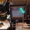
2) A sensor for feedback, usually an encoder. Optical encoders are pretty standard, but get quite pricey if you want high resolution and/or absolute position information. We were intrigued by some of the cheap, high resolution magnetic encoders offered by vendors like AMS. It turns out that although they claim 12 and 14 bit resolutions (that's 0.09 and 0.02 degrees respectively), they suffer from non-linearities on the order of a degree or so! However, we found that this non-linearity is very repeatable, and we were able to develop a quick, self contained (on motor) calibration routine that restores resolution to better than 0.1 degrees. (More on this later. This was a significant design effort and is worthy of its own build log!)
3) Drive circuitry/power electronics to excite the motor windings. Many industrial servos use discrete H bridges. Each phase requires it's own H bridge ( for a two phase motor... half bridges for each in a three phase motor), which consists of at least 4 if not 8 (...including freewheeling diodes) discrete switching devices. Throw in gate drive circuitry, and things start to get expensive. We hoped to find a single-chip, integrated solution that would allow for current feedback, and we found just that in the A4954 dual full bridge PWM driver.
4) Control Electronics. Usually a microcontroller or FPGA. Early on, we decided that Arduino compatibility was a must in order to make the firmware as accessible as possible. We chose to use a SAMD21 ARM M0+ (Arduino Zero compatible) processor to balance cost and performance. Our breadboard prototype system verified that this processor was more than capable of executing the necessary algorithms....
Read more »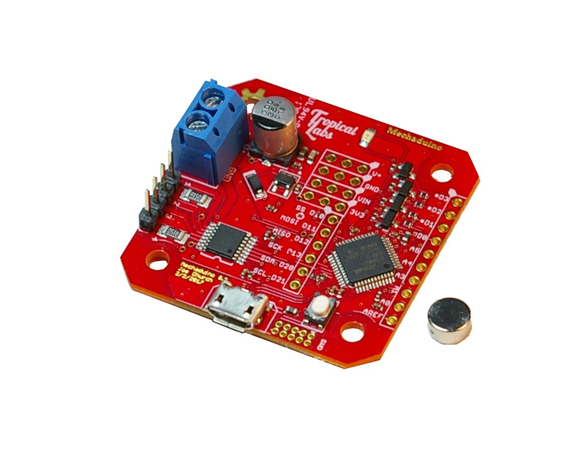

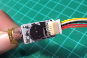
 You will need to mount the magnet
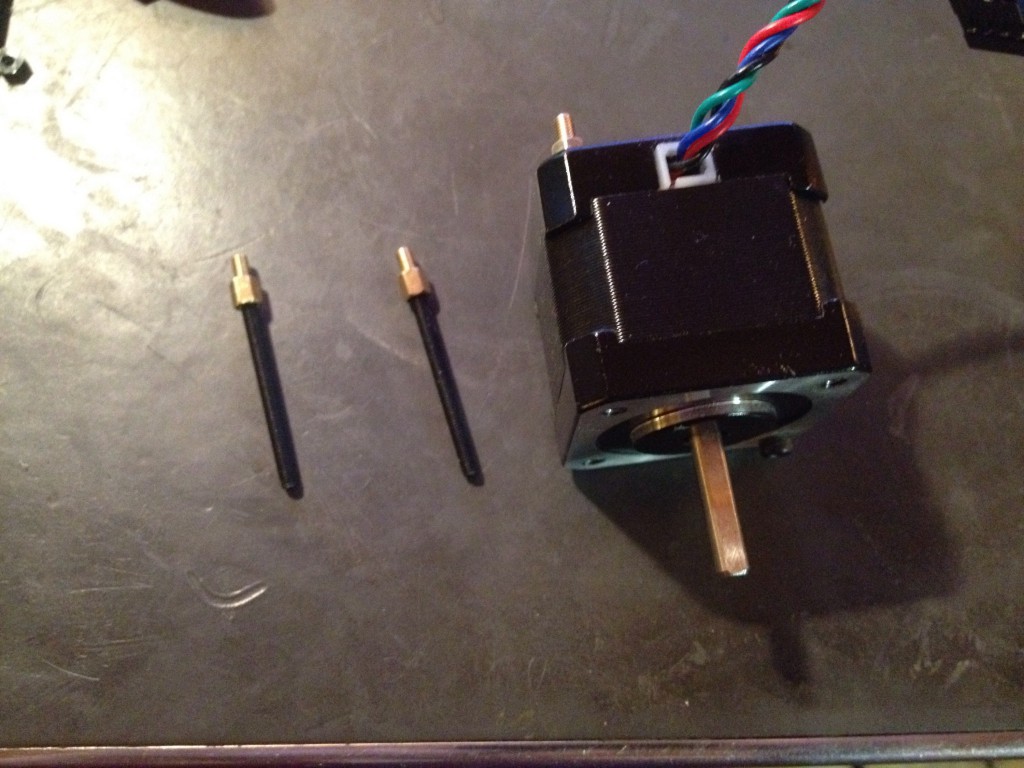


 Danny FR
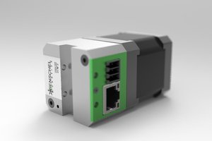
 Chris
Chris
 ksk
ksk
 Nicholas
Pins D1 and D0 can be used as step and direction inputs.