 ivorivetta
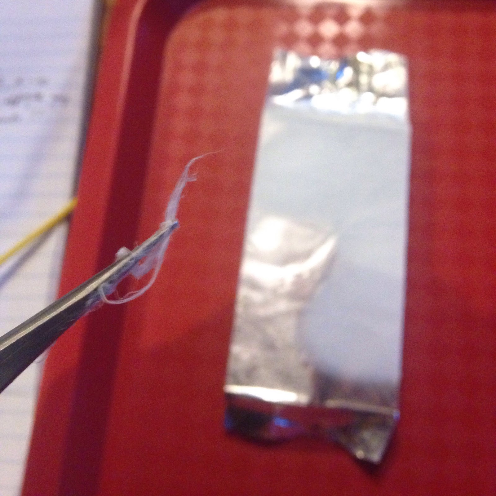
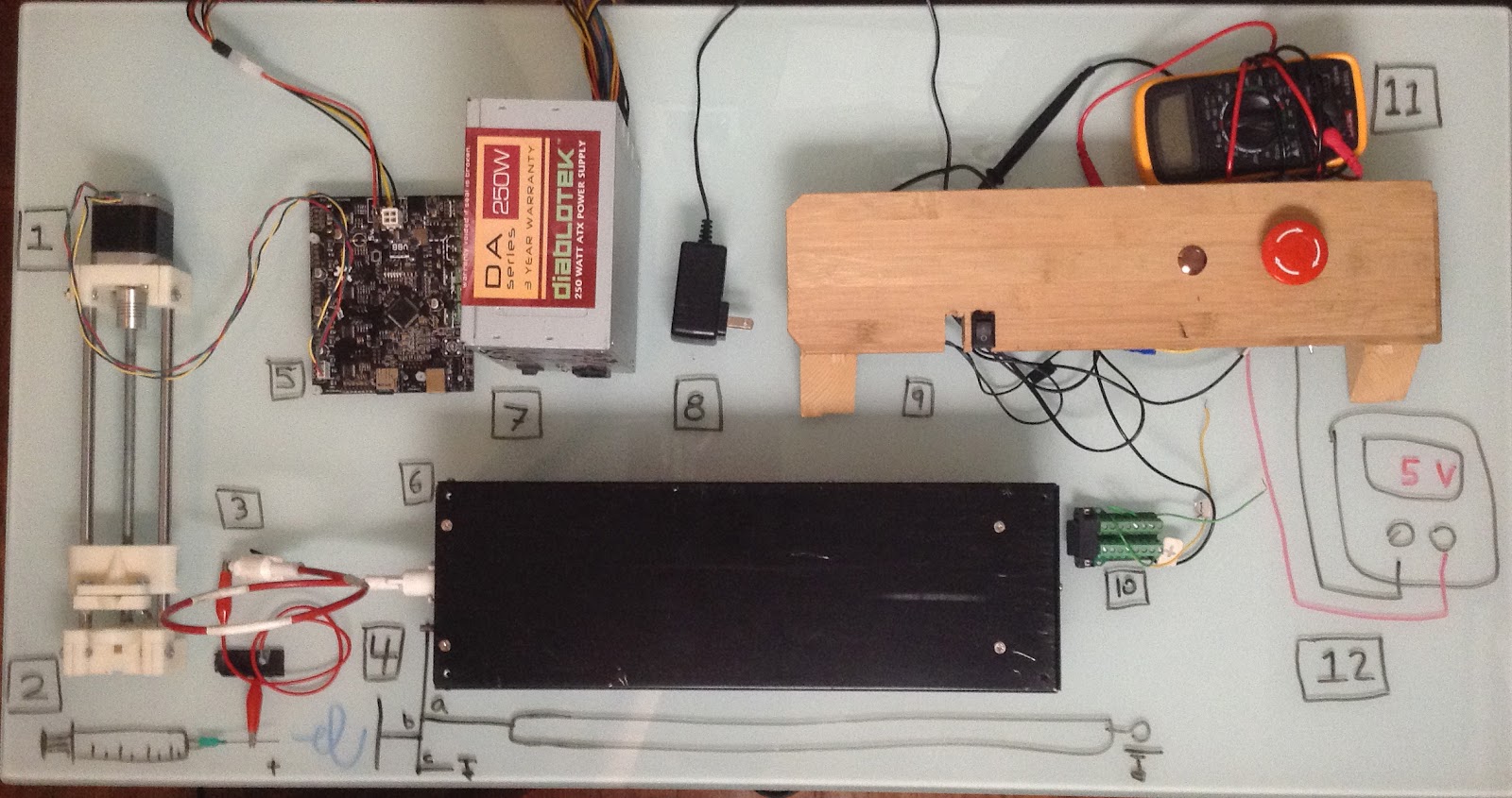
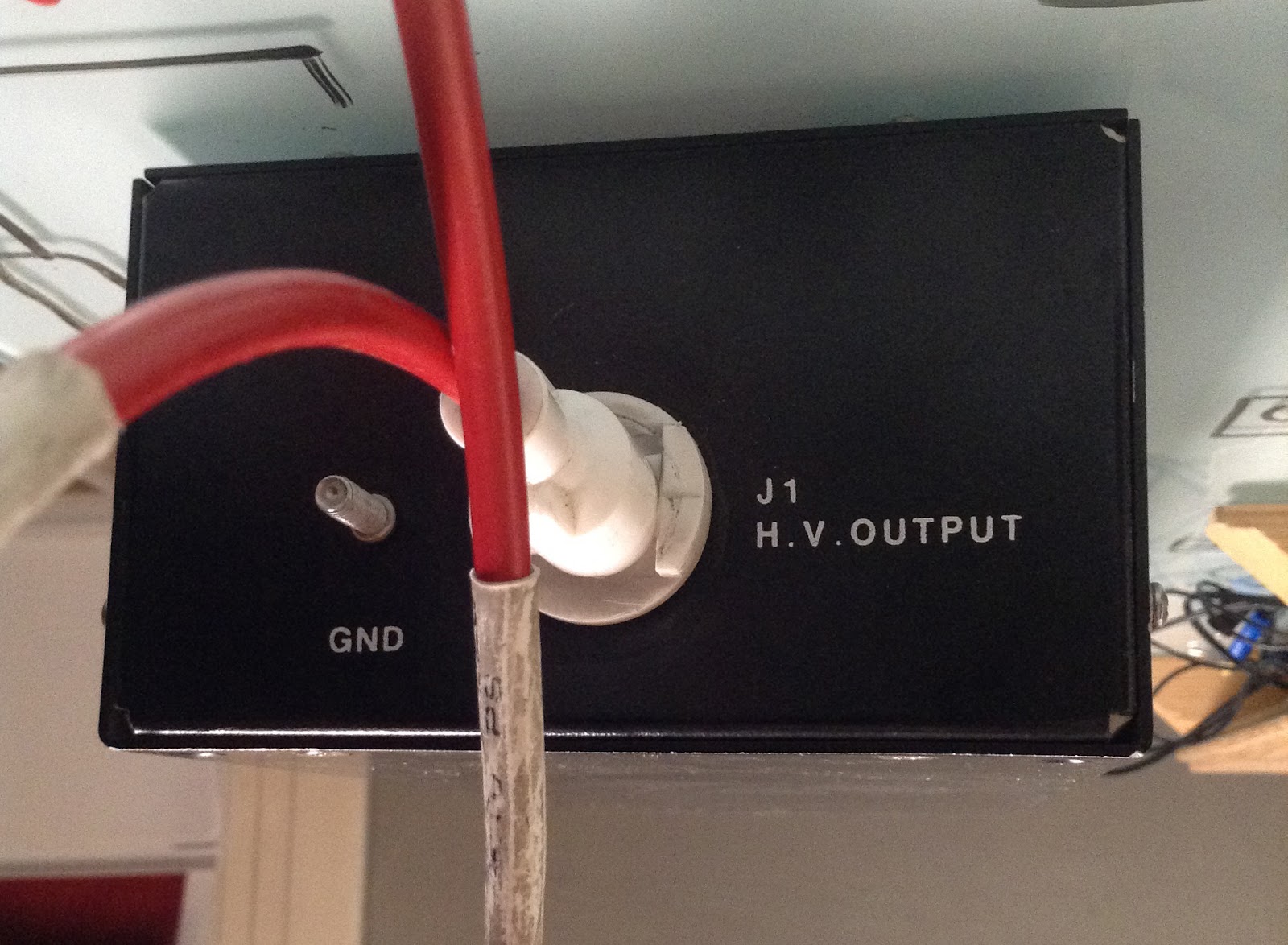
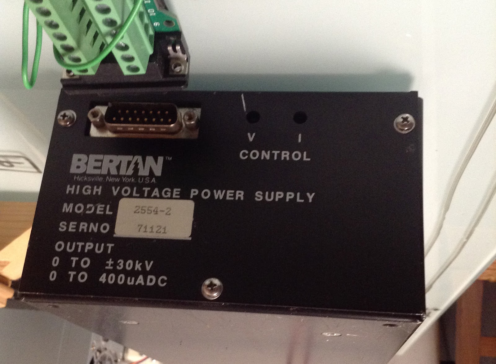
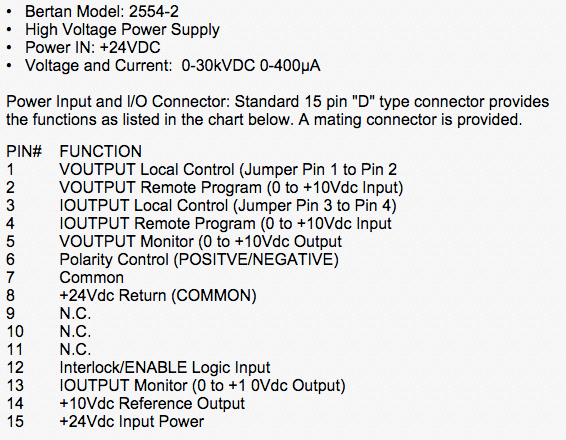
This physical electrospinning set-up is designed to push the capabilities of my garage and budget. Aesthetics take a backseat to functionality where duct tape and repurposed household appliances meet. Most of the time and budget went to ensuring that the high voltage component of the system was safe and functional.
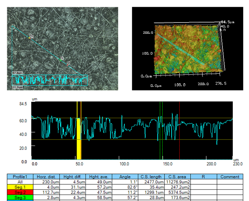
A major consideration when messing around with nano and micro-scale processes is how you will image and test your results. I would love to build my own lab bench SEM, but in this case I had a hacker comrade who happens to be a doctor in materials science with access to research style facilities and who signed up to explore this process with me. We are both excited to explore the potential of combining our particular prototyping experience and experimental prowess.
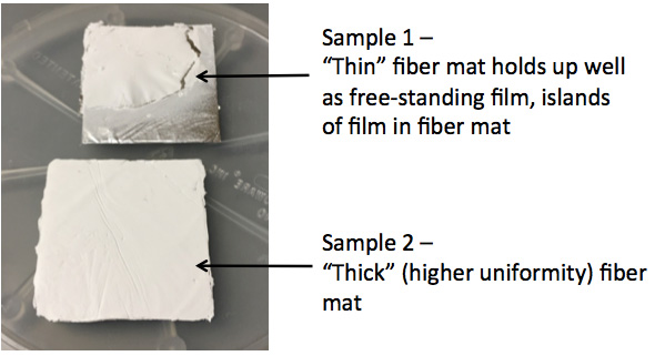
At the end of the day, we wanted to produce lab-quality results and realize a general “materials platform” we can rely on for future applications, in our shared bag of tricks. Electrospinning isn’t a magic bullet to solve every problem but is cool enough to invest time and creative attention. We already have many applications in mind, which we believe there may be immediate results or improvements, such as for tissue engineering, sensors and power harvesting.
In the most general sense, an electrospinning set-up is a syringe tip charged to 10,000+ Volts with a ground collector spaced ~10 cm away. The fluid is pulled into fiber threads with the force of the electric field extended between + and -, and everything is tuned so that the excess fluid evaporates off by the time it lands on the collector:
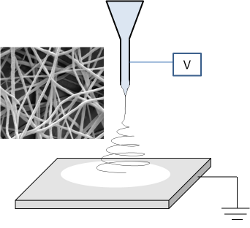
(src: www.electrospintech .com)
For a clean e-spin build, look no further than the progress [Douglas Miller] has made on his low-cost, open source electrospinning machine. I wish mine looked so modern. In the commercial world, Electroloom is also doing a great job pushing the field and producing actual wearable garments.
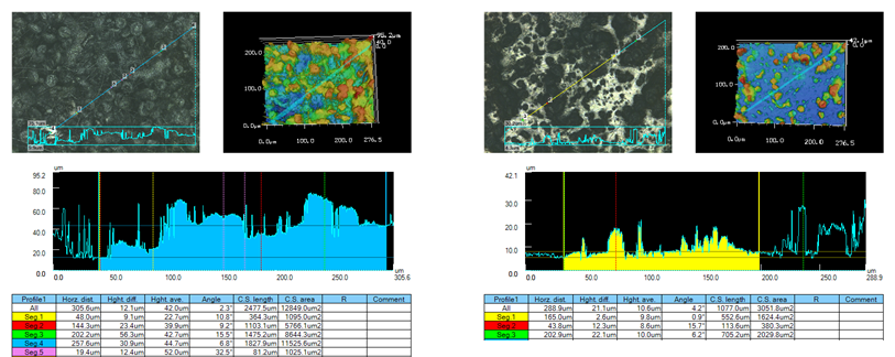
This write-up will be more process development focused and I’ll share lessons learned relating to mechanical and electrical problems as I go. The brunt of the work occurred between February and May 2016, with the latest round of testing and imaging finishing up around June.
SAFETY WARNING: Taking high-voltage safety seriously is a life or death decision. Do not attempt w/o previous experience. Stay safe!

 Collin Matthews
 Tony
Tony
 Jakob Wulfkind
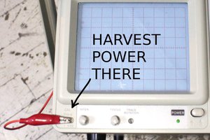
 Yann Guidon / YGDES