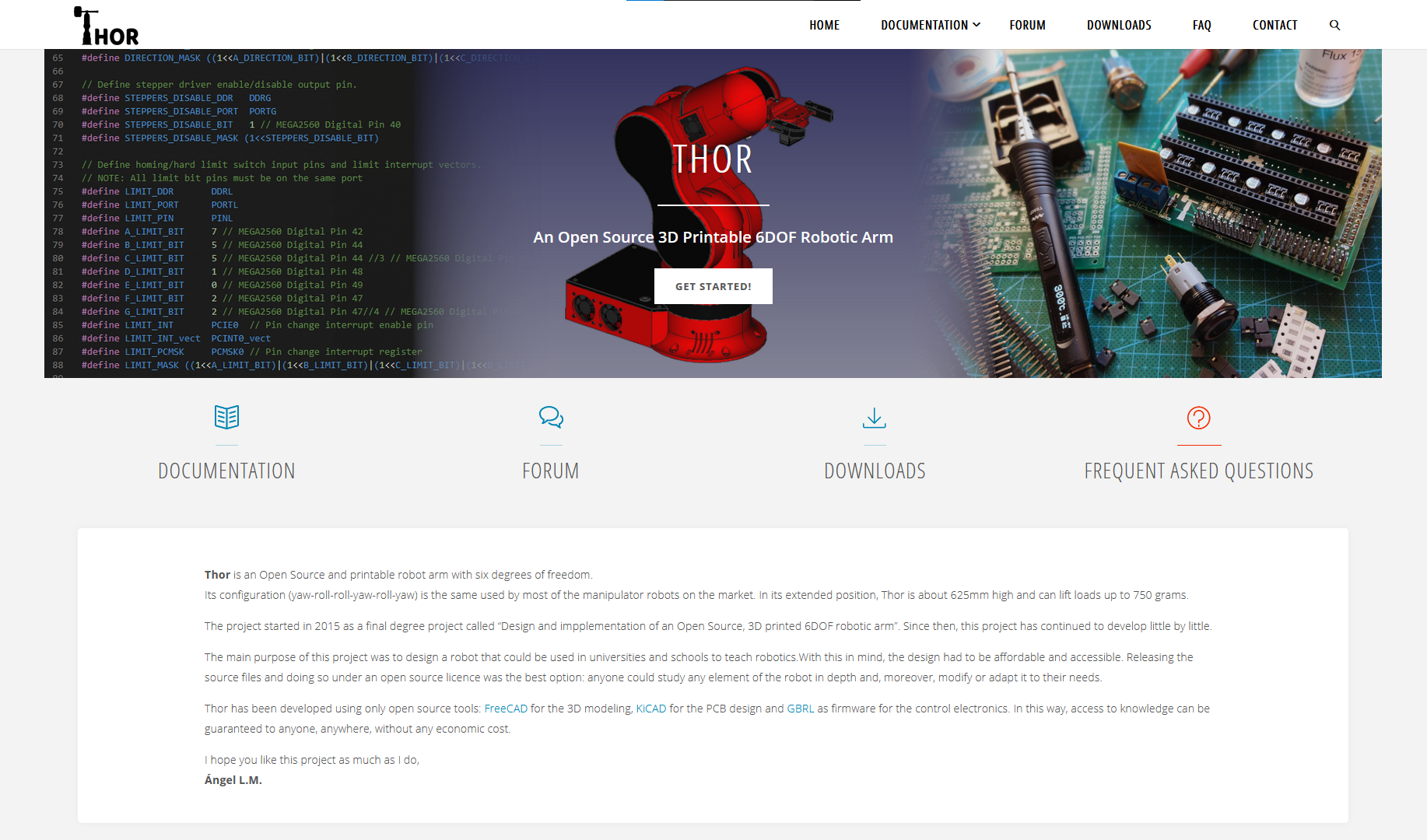
At Thor's Website will find updated info about this project, manuals, list of materials, the community forum and much more. Visit us!
To develop this project, I have been involved in several areas of expertise:
Hardware choice
In order to have a nice accuracy on the moves without raising the price too much, I chose stepper motors for the movement transmission. I had to choose stepper motors with mechanical reduction for the second and third articulation in order to manage the torque generated in these articulations. For the two last DOF I chose smaller steppers with the purpose of reducing their weight.
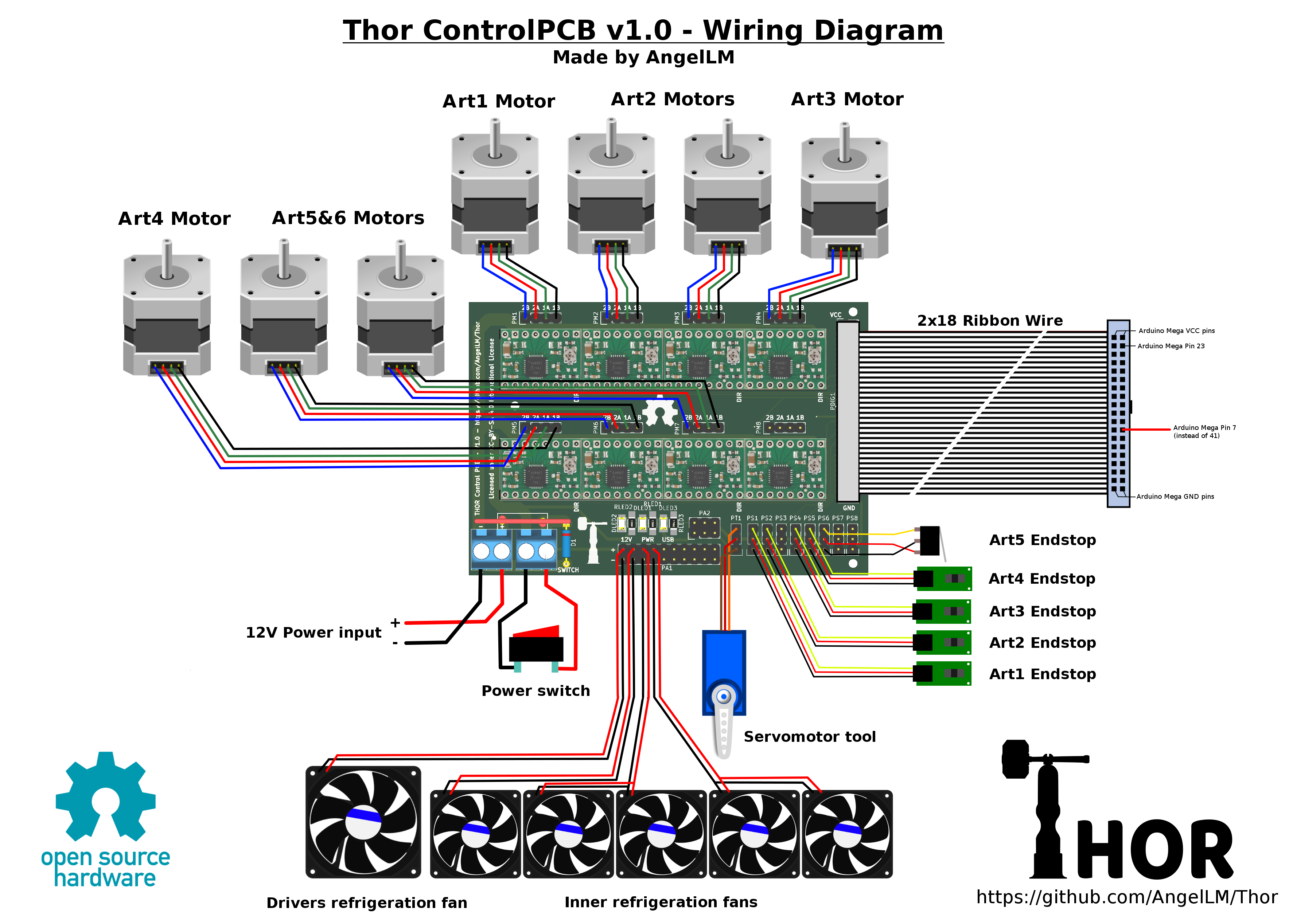
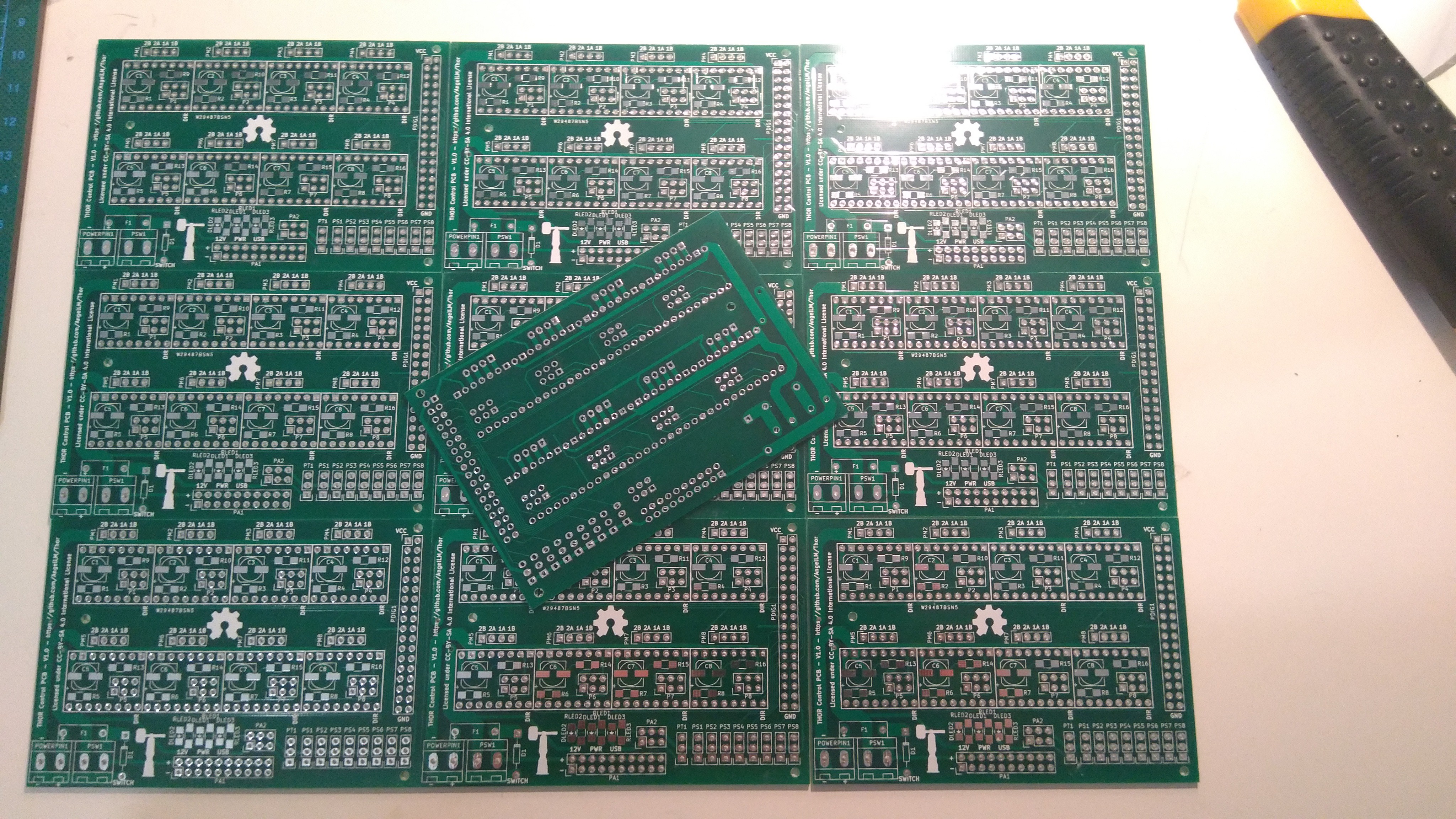
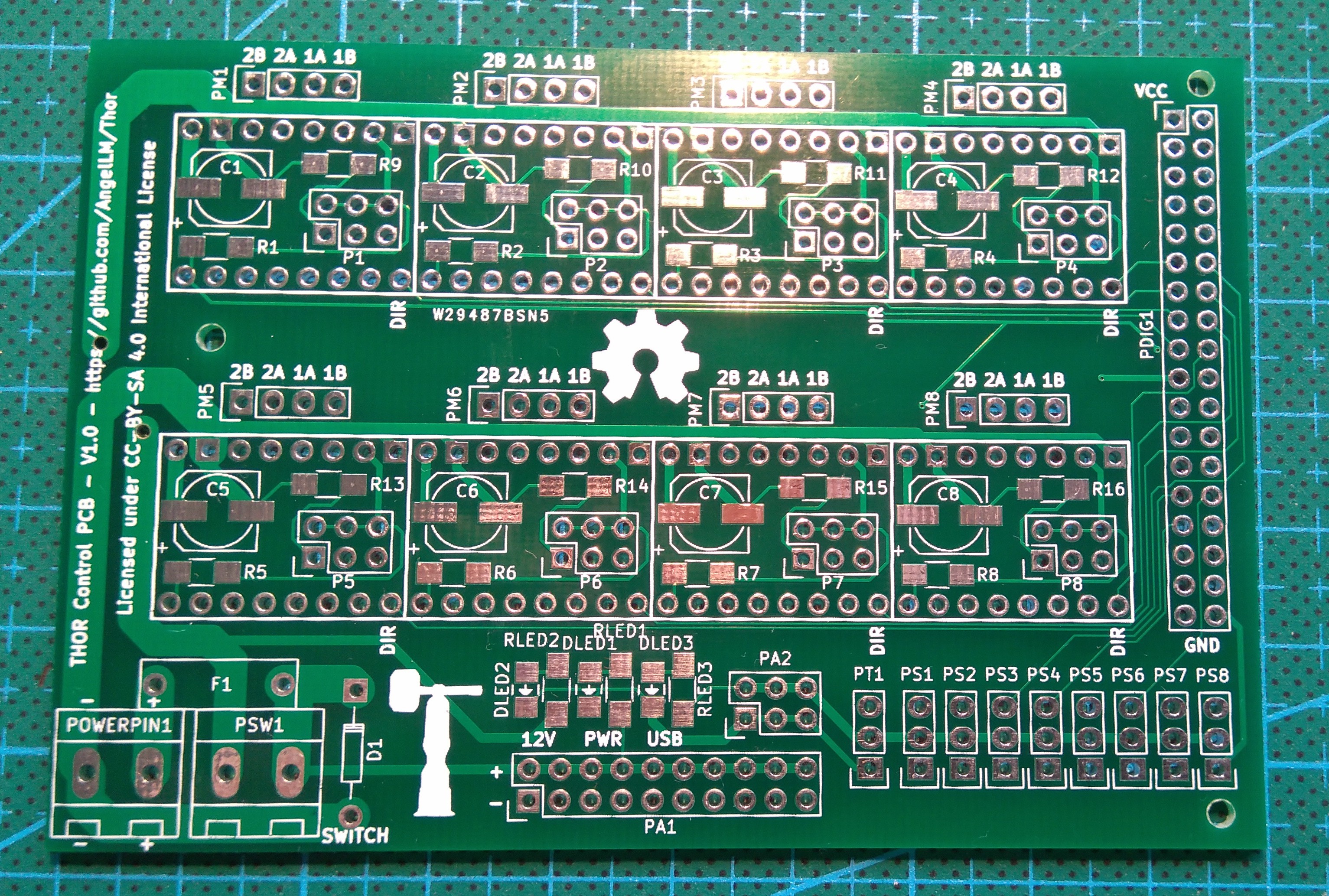
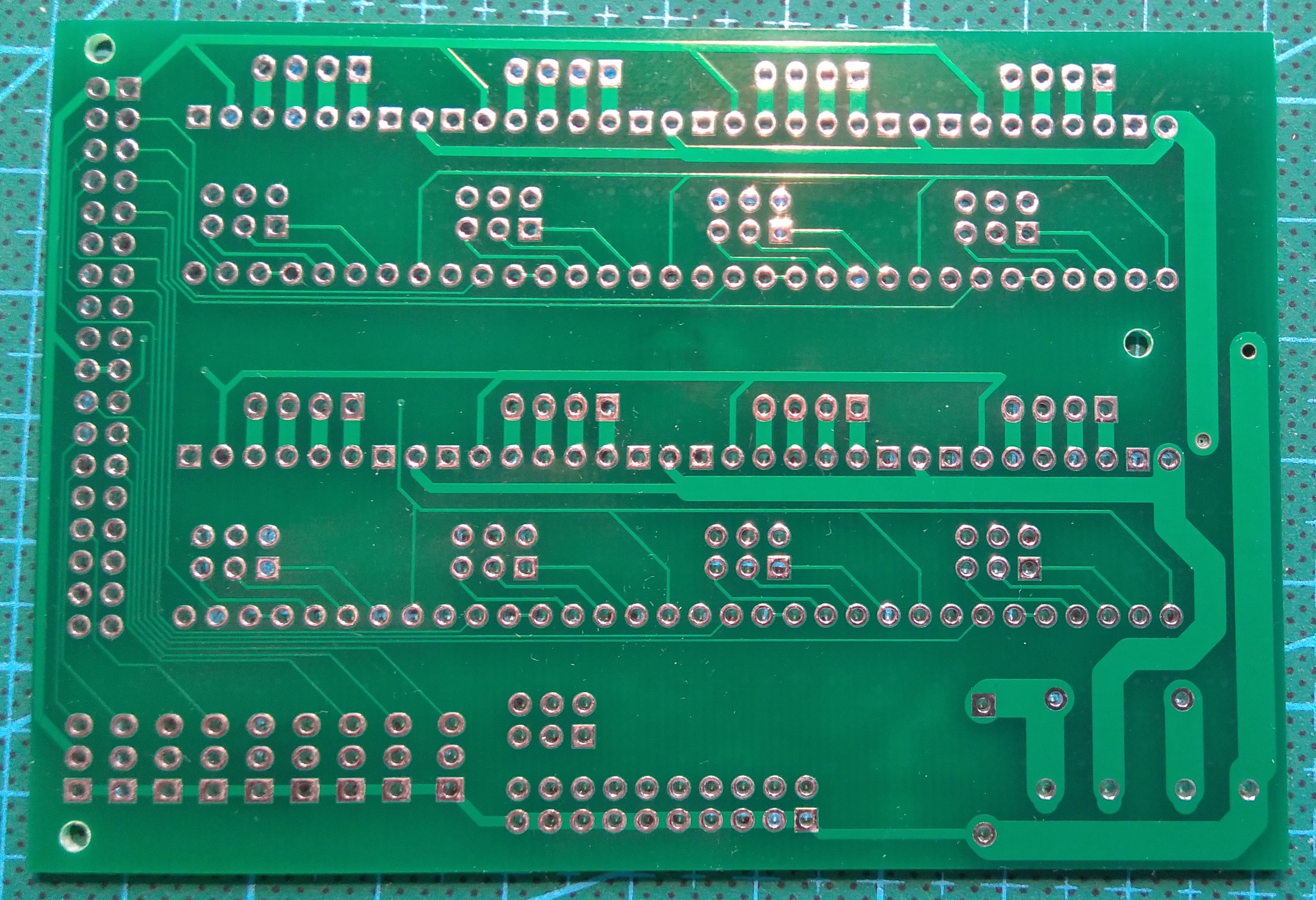
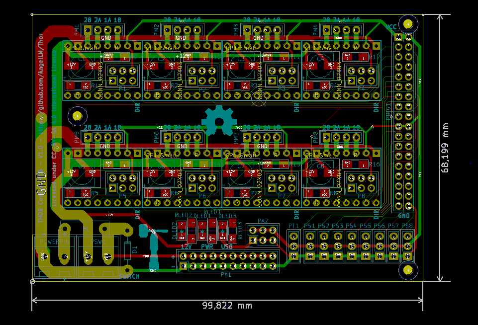
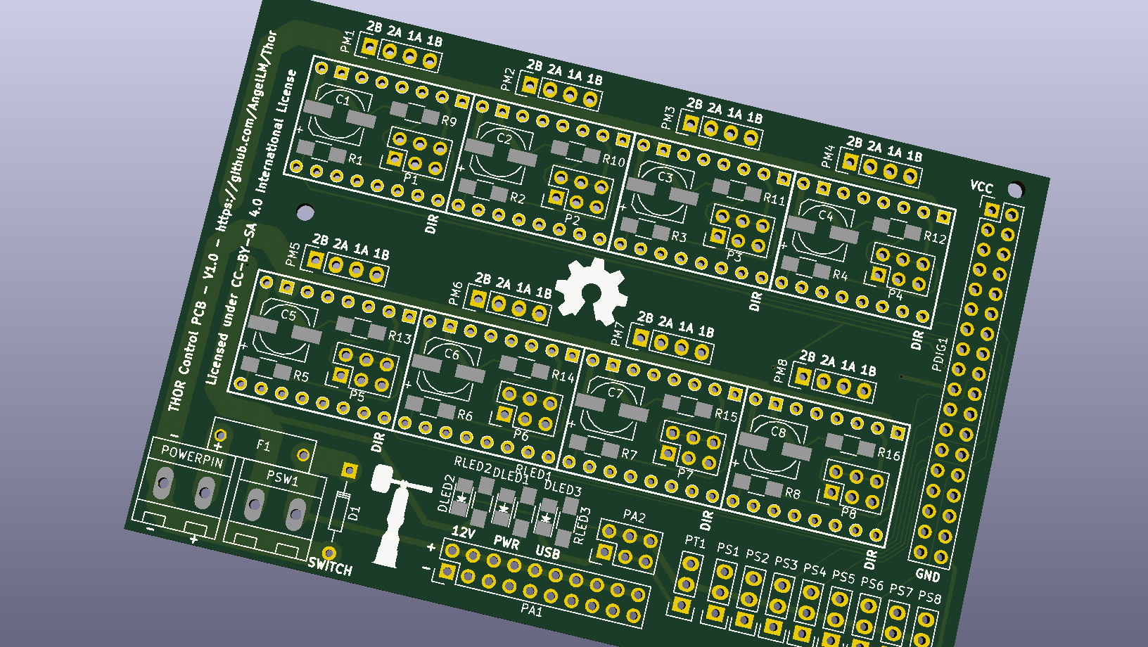
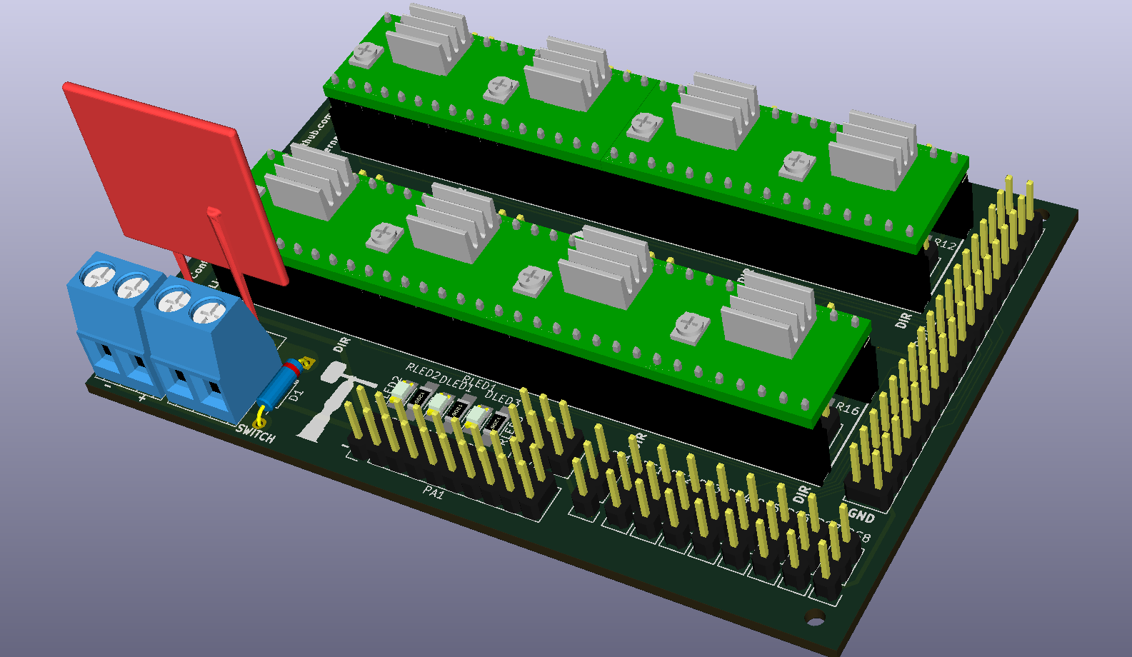
For the electronics I chose an Arduino Mega as main controlling board. And I designed a "shield" to make possible the control of 7 steppers. I chose pololu A4988 as stepper drivers.
For the transmission of the third, fifth and sixth articulation I have used GT2 Pulleys and GT2 Belts.
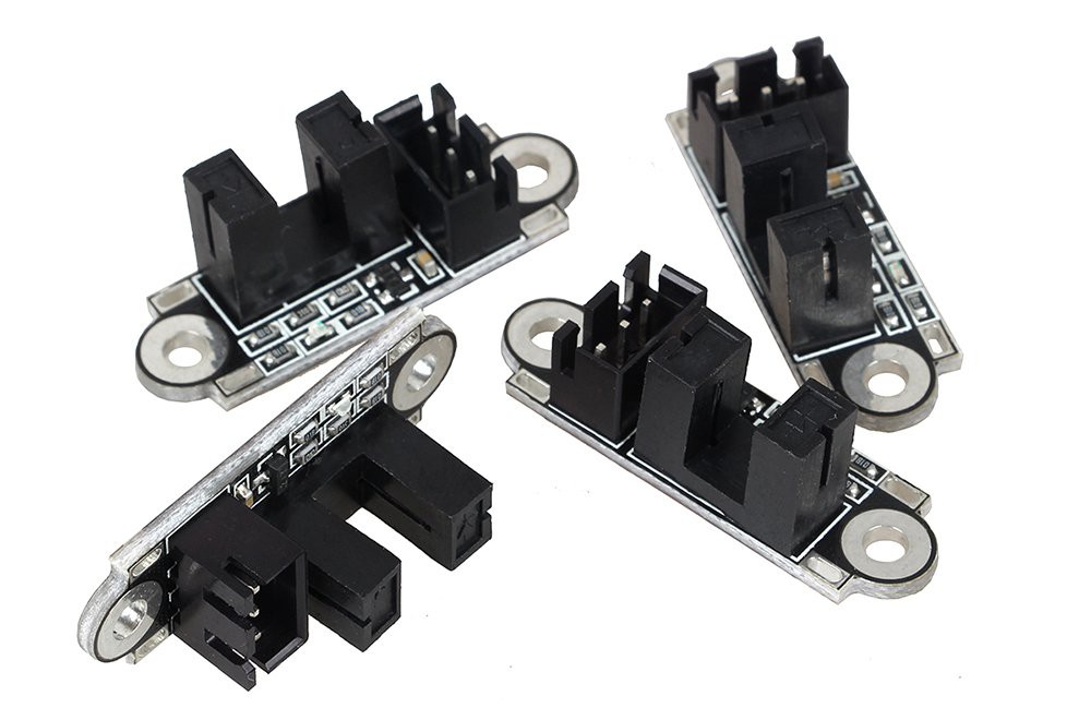
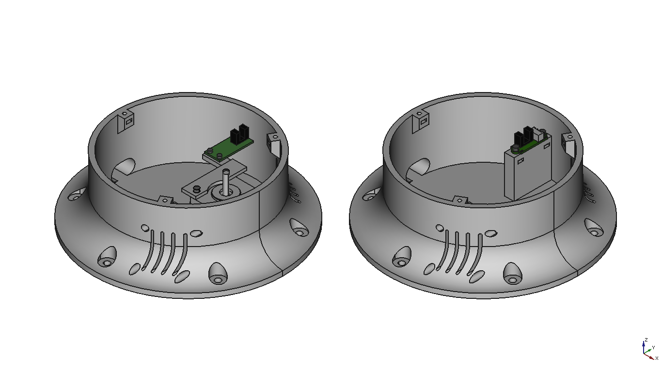
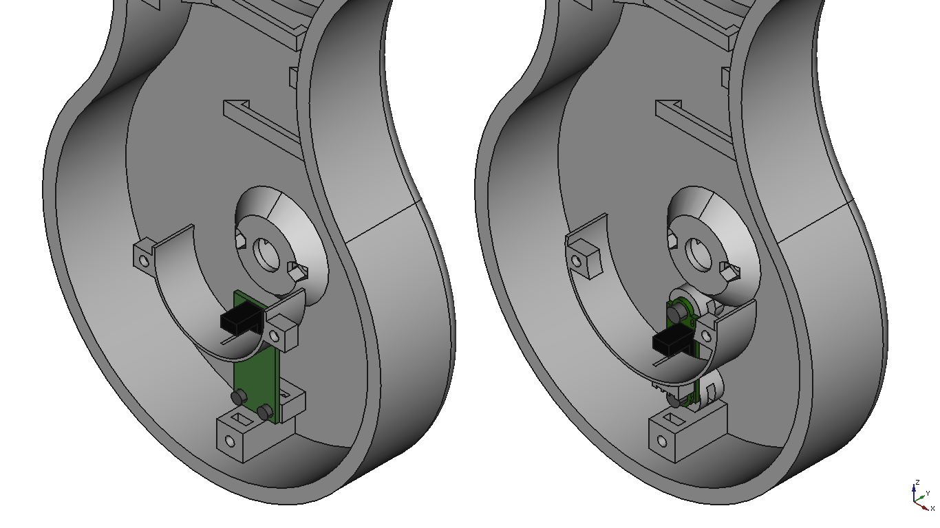
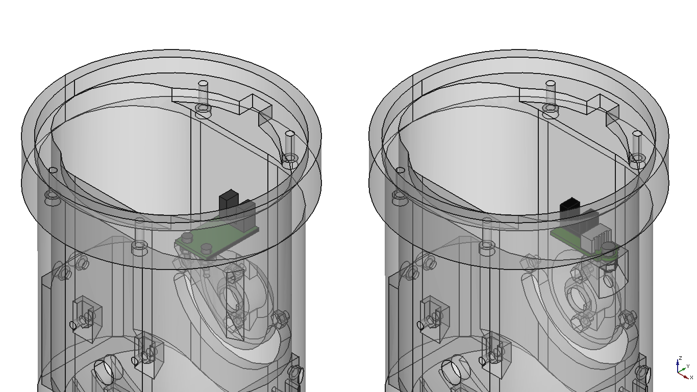
Finally, I chose optoisolators and a micro-endstop in order to establish a home position for the first five articulations. Using optoisolators instead of mechanical stop allows it to rotate more than 360 degrees without colliding with the sensor.
As you may have realized, all of the hardware I have chosen is commonly used on DIY 3D printers.
3D Design
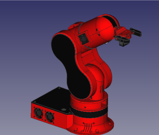
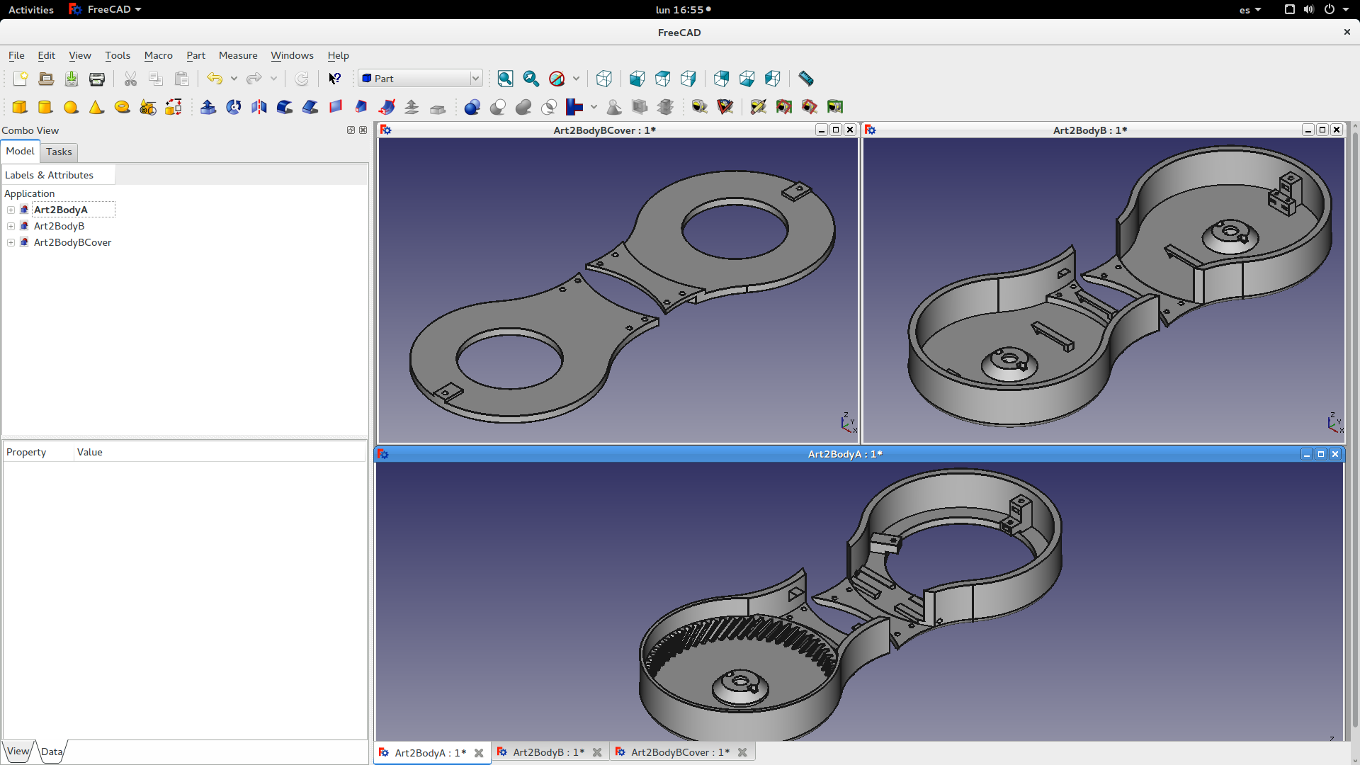
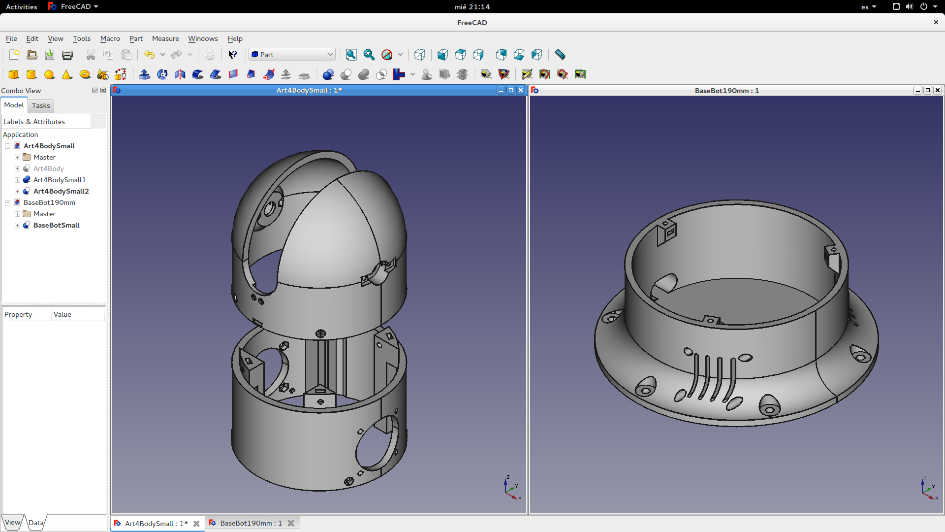
I used FreeCAD software in order to design the pieces of the robotic arm. There are 37 different printable pieces in Thor. For every piece there have been a lot of iterations behind the final one.
Some design solutions are inspired by commercial robots, others are the result of hours of work and others are just serendipitous ideas.
The final design had to be compact and safe. I wanted to hide every motor and every single wire to make it more aesthetic. Also, I designed covers and protections to reduce the risk of entrapment while the user is manipulating the robotic arm.
None of the 6 DOF is a end-effector. There are a lot of commercial and DIY grippers/vacuum/hooks around the web and for each use something different is needed. Instead of integrating a gripper into the design I decided to make an adaptable design making an interface between the end-effector and the robotic arm. This way you have 3 options to include a tool on Thor:
1. You can modify the interface, placing the mounting holes wherever you need them.
2. You can modify the tool, matching its mounting holes with the interface ones.
3. You can design an intermediate piece that fit with the interface on one of its sides and with the tool on the other side.
I like the whole robot, but I'm especially proud of these 3 solutions:
- Semi differential (5&6 DOF)
This kind of transmission allows it to do two types of movements using two small gears that act over a big one. When the small gears rotate in the same direction, the big gear bloks and rotates around the small gears' axis. When the small gears rotate in opposite directions, the big gear rotates around its own axis.
This way, actuating over the two small gears allowed me to place the steppers as lower as I could, transmitting the movement with GT2 belts and reducing the torque generated by the motor's weight.
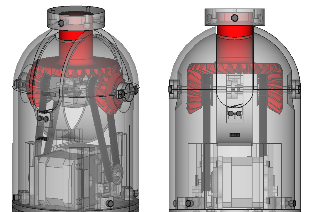
- Support point of 2nd DOF shaft
While I was designing the second and third articulations I was worried about the available space. The motors tookup a lot of space and there wasn't a single small area to establish the second support point for the second articulation axis. The solution was one of the serendipitous ideas I have mentioned early. Why not use the shaft of the stepper of the third articulation as the support point for the second articulation axis? And voila! It worked well.

- DIY Bearing
The design of the 4th articulation had an issue, I didn't find a commercial bearing adjusted to my needs. After days of searching, I decided to make my own. Inspired by a solution that some users used for the Ciclop's bearing, I designed the bearing using 6mm airsoft balls as bearing balls. The result was precise, almost without backlash (after some printing...
Read more » AngelLM

 You will find the full resolution image & source files at the







 Michael Graham
 Peter Sinclair
 Steve Anderson
 Maximiliano Palay
How much Fillament do you need?