 Jakob Wulfkind
Makers often find themselves in need of some pretty high-powered devices, such as welders, plasma cutters, laser power supplies, and coilgun drivers. They also often find themselves very very poor. This project is an attempt to bridge that gap, by creating a pulsed power supply capable of driving high-wattage equipment from wall current for under $100.
Ideally the finished project should meet the following criteria:
*Able to be built for less that $100
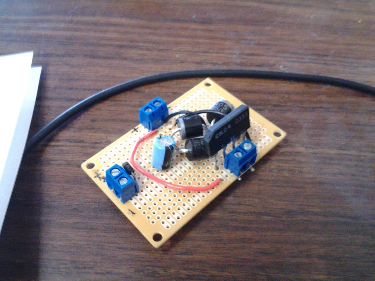
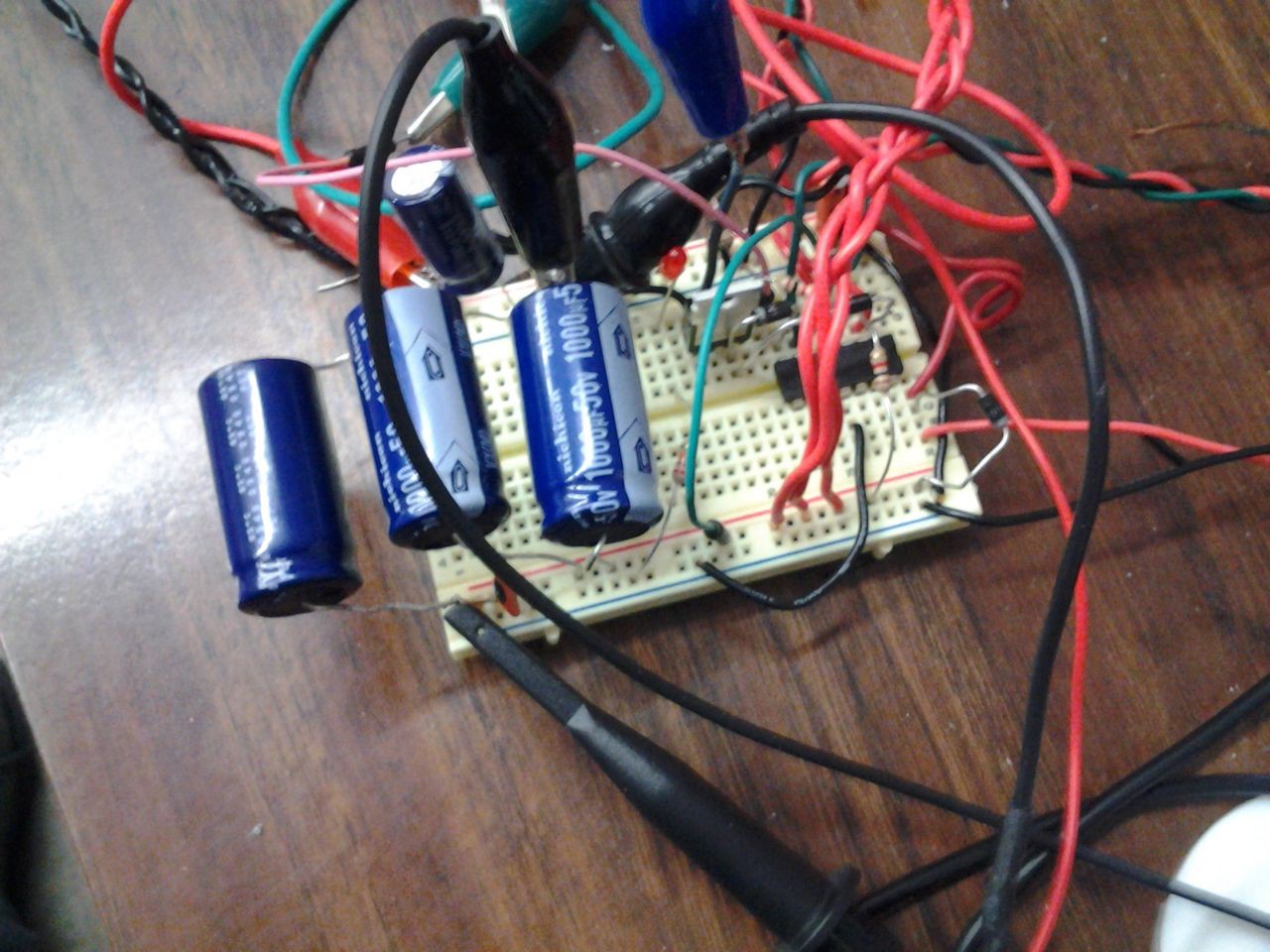
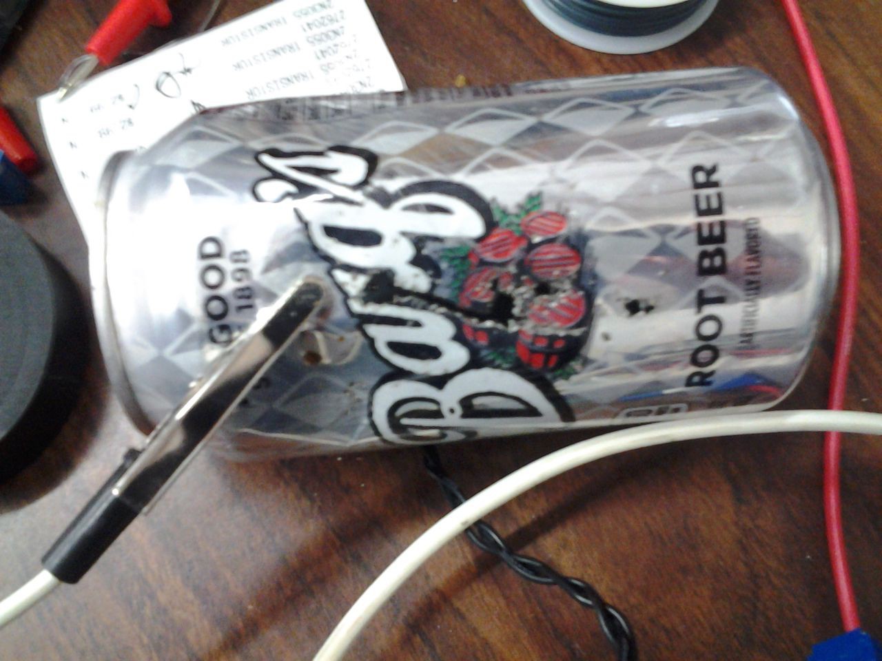
*Easily adapted for variations in available components, with no reliance on components that couldn't be salvaged from readily available consumer electric devices.
*DC Square Wave, AC Square Wave, and AC Sine Wave outputs
*Capable of driving a welder that can weld 1/4" steel
*Capable of driving a plasma cutter that can cut 1/4" steel
*Able to be operated by a normal American wall power socket (~110V at 60Hz and ~15 amperes).
*Able to be easily swapped between different applications, without the need for anything more complicated than a checklist and connection diagram.
*Able to accept commands from other electrical devices
*Should be as safe as or safer than other welders on the market.


 Collin Matthews
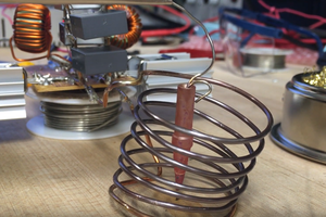
 jdunbar360
 Yann Guidon / YGDES
 CaptMcAllister
Hi! This is a really cool idea, especially with its use of such cheap or easily salvageable components!
But ... Why not use a microcontroller like an ATTiny to control the charge/discharge cycles of the capacitors? It would be cheap to obtain, and could do a little more than the two OpAmps.
Or does that fall out of the scope of "Salvageable component"?