Close
0%
0%

ScoPower

You know that calibration point on your 'scope? Well actually it's a tiny power supply. Here is the adapter and it's cheap!

Similar projects worth following
I was needing a 32768Hz source to trigger my scope, yet I didn't want to resort to a lithium coin battery like my previous application using the DS32KHZ integrated oscillator. Then I realised I could just avoid the whole battery thing if I considered the 2Vpp calibration point as an AC power supply...

Considering the very low power consumption of the DS32KHz, a simple charge pump made of very low-drop diodes is enough to get about 3.6V.

This gizmo lets me tune 32768Hz oscillators, as shown on this video:

The original project is there: Integrated 32KHz clock source but the battery is a major practical problem. The battery

  • needs a switch to turn on/off
  • takes room
  • might not work in the very long term

So I designed a tiny charge pump, and I don't have to care about the battery.

I applied and extended the principles of this project to #Active scope probe with no dedicated power supply


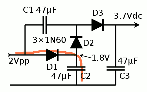
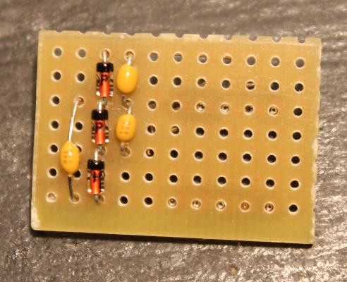
Actually, the probe test point is not real AC so it's hard to rectify like a 0V centered sine. A total of 3 diodes and 3 capacitors are required and can provide maybe 100µA (I should plot the I/V curve). More than enough for the DS32KHz rated at 1µA, and some other simple circuits (a µC maybe ?).

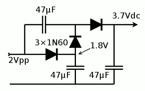
I initially used 100nF capacitors and I measured about 3.7V with no load. Well apparently, 100nF is nice for a proof of concept but this barely lets the DS32KHz startup. I replaced all the capacitors with 47µF and it works like a charm!

The average voltage will drop with a little load and ripple will appear. But that's inherent to all charge pumps. A dedicated high-efficiency integrated circuit, a ICL7660 or a Joule Thief would bring some benefits but simplificy, cost and speed of development/implementation are other key parameters.

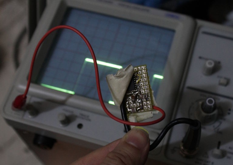
Other techniques are possible, such as a direct connection to a transformer to elevate the voltage but the frequency (1KHz on this scope) is usually too low...

I chose to not regulate the output further. The 47µF should smooth the power enough and the DS3231 is not an ultra-precise timebase so any futher regulation will not provide any advantage, cost more, draw more power->increase ripple etc.

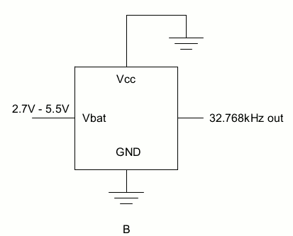
I have low-power regulators but the DS32KHZ draws so little power that the ripple is not significant. Of course this will also depend on the make/brand/design of the scope (are there 1Vpp versions ? more capacitor stages then). But the DS32KHZ needs from 1 to 4µA in operation, at 2.7 to 5.5V according to the datasheet, which has the following illustration:

Deviation of the rated frequency is expected to be the least around 3V, so 3.6V is not far and precision does not suffer much. I repeat, it's not designed for extremely precise tuning, just to get within a fraction of Herz...

Per the datasheet: "The DS32kHz I CC and I BAT currents are specified with no output loads." Since the 'scope's input impedance is 1M Ohms, the output will draw 4µA@4V (divided by two due to "almost 50% duty cycle"), which must be added to the internal consumption.

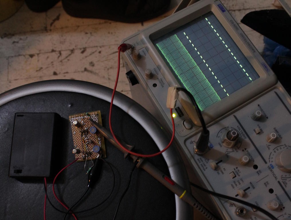
I see a periodic dip of the square trace and this corresponds to the 450µA drawn to measure the temperature and adjust the clock's capacitance. See the log Power dips, NOFIX

I don't have a digital scope so i can't capture the duration of that dip, it appears too infrequently to be observable on a phosphor tube...


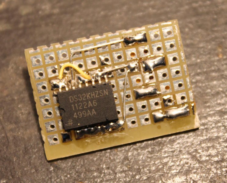
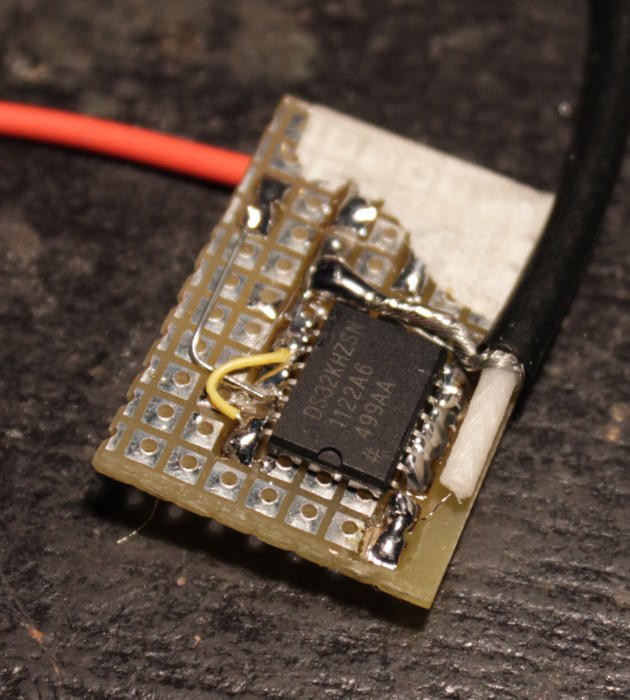
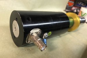
Economy comes from reusing available parts, such as a half crocodile clamp/wire and a segment of BNC coax cable (from an old broken scope probe). Overall it takes more room but it does not require its own probe or something... There is no detachable connexion but there is enough length to reach across my scope, from the probe test point to the external trig input BNC.

Now I'm waiting to see how long it takes for this gizmo to be sold for $2 by Chinese sellers on aliexpress and eBay :-D

(Extra savings would come from hooking a BNC connector directly on the board but AFAIK these things don't come as male)


I consider this project "completed" because it delivered the required features, which were pretty small, but the circuit deserves a project on its own.

The adventure does not stop here however since I started #Active scope probe with no dedicated power supply which will also contribute to my study of crystal oscillators !


Logs:
1. Efficiency
2. ScoPower in action
3. Assembly
4. Power dips, NOFIX
5. Charge pump design
6. Tuning for a different frequency

  • 3 × 1N60 (very low drop Germanium diodes) very low drop diode, Germanium
  • 3 × 100nF ceramic capacitors
  • 1 × DS32KHZ (32768Hz integrated oscillator)

  • Tuning for a different frequency

    Yann Guidon / YGDES04/19/2016 at 23:57 0 comments

    I thought that all was said and done about this project, but then the tubes came and the choice of the different frequency (18KHz) creates new questions, until I receive that Rb frequency standard.

    I just realised that I could simply find an existing quartz with a multiple of the desired frequency and divide it with one 74HC4040 (I have mutliple reels of these, don't ask me why)

    So what frequency is easily divided by 18000 ? 18.432MHz gives a perfect division factor of 1024. However this consumes a LOT of current (in the 10mA range).

    A lower frequency could work but I don't have 9.216, 4.608, 2,304 or 1.152MHz in stock.

    I have a bunch of 3.6864MHz and I built an oscillator there : https://hackaday.io/project/8121-discrete-yasep/log/26870-clock-generation-circuit I measured a 1.6mA power consumption, which is a bit too much. Given my latest experiments, can I draw less ?

    The division ratio is also a little bit "odd", giving 204.8. The idea so far is to show 5 cycles on the scope, at 18000/5=3600Hz (277µs). The 4040 will divide by 3686400/3600=1024. So this design will be actually a 3600Hz generator...

    For more flexibility, jumpers will select the frequency. But now the most critical aspect is to reduce the power consumption and ripple. So now is the time to create a new low-power oscillator, using all the squillz I earned with the other crystal oscillators.

  • Charge pump design

    Yann Guidon / YGDES04/10/2016 at 22:28 0 comments

    I wouldn't have thought about this project if I wasn't actively developing circuits using Germanium parts. They have a very low switching voltage, around 0.2V, unlike the silicon diodes (0.6 to 0.7V). This makes energy harvesting possible and this was essential in the age of crystal radios...

    This low drop is also useful to extract small current from low voltage signals. Germanium diodes (the "detector" type) can't handle much current (20 to 40mA peak max) but there the losses are minimal: if we consider the first third of the charge pump (made of D1 and C2), the efficiency is about 90% (0.2V of drop for a 2V signal).

    This first stage of "simple rectification" is necessary to provide a first "base" voltage of 1.8V for the actual charge pump. The actual elevation of voltage comes from C1 but it can't work if it starts from 0V.

    Let's now consider that after a few cycles, C2 is fully charged. When the input is low, C2 can't discharge through D1 (we'll ignore the leakage currents which was barely measurable in a https://hackaday.io/project/10698-clockwork-germanium/log/35373-germanium-diodes)

    So there is a difference of voltage between the electrodes of C1. When a rising edge comes, the difference remains, which "pulls" the anode of D2. Since this is the conducting direction, current flows though D1 and D2, effectively charging C1 (and C3 through D3, the last recitification stage).

    When the input signal falls, D3 prevents the discharge of C3 and D2 prevents the current from going back. Charges are trapped at 2× the input voltage !

  • Power dips, NOFIX

    Yann Guidon / YGDES04/10/2016 at 18:14 2 comments

    While using the thingie, I noticed dips in the traces.

    At first I thought is was a bad contact but I noticed it came back regularly. I vaguely remembered the datasheet that says (quoting)

    "The DS32kHz module contains a quartz tuning-fork crystal and an IC. When power is first applied, and when the device switches between supplies, the DS32kHz measures the temperature and adjusts the crystal load to compensate the frequency. The power supply must remain at a valid level whenever a temperature measurement is made, including when V CC is first applied. While powered, the DS32kHz measures the temperature once every 64 seconds and adjusts the crystal load."

    Said datasheet gives a typical consumption of 450µA (half a milliamp) which is 100× more than the average consumption (about 5µA). This explains the dips of the traces but also why I had to add the 47µF capacitors ! The 1/2mA peak appears during power-up and it didn't let the charge pump rise enough.

    This is now solved with the large capacitors with no increase in complexity.

    So yes, this circuit won't be able to supply 1mA :-)This dip (about 1/5s long) is not annoying enough to require a fix since the trigger still holds. Which is all I asked in the first place. But without this dip, I wouldn't have looked deeper in the datasheet to look at the current drawn during temperature recalibration...

  • Assembly

    Yann Guidon / YGDES04/10/2016 at 16:04 0 comments

    I forgot to post pictures of the circuit before it gets wrapped/protected.

    The construction is really easy and the parts cost is negigible. Beginners can make their own circuit for a few dollars at most.

    The 1N60 could be confused with bland 1N4148 but their characteristics are different. The really lower voltage drop is essential to make this work !

    Soldering the wires was more delicate though. The coax' core is fragile, a single thin strand that breaks easily. The board must be physically rugged.

    The first attempts were inconclusive : I saw a 32KHz signal hashed by 1KHz blanks. The diagnosis was easy to reach : the DS32KHZ needs a bit more current than I thought. I dug again in my parts collection and chose 3 SMD 47µF /6V capacitors (that's about 20µF effective at 3.5V)

    Here it is, with the added capacitors, outputing a solid 3.6V square wave:

    Now this thingie is used to tune a Germanium-based Xtal oscillator. Let's say it's very convenient !

    And the wires are long enough to reach the other side of the scope, where the external trig input is located.

  • ScoPower in action

    Yann Guidon / YGDES04/10/2016 at 07:03 0 comments

    Once the power supply question solved, the system works very well, is practical and useful for my Xtal tuning needs :-)


  • Efficiency

    Yann Guidon / YGDES04/10/2016 at 05:14 0 comments

    Those 1N60 are working great !

    Just by touching the crocodile clamp, it generates 1.3V (yes there is a strong 50Hz induction here).

    Is that an idea for ambient power harvesting ?

View all 6 project logs

Enjoy this project?

Share

Discussions

eywdck2l wrote 08/14/2023 at 02:00 point

You said 1 kHz was too slow for a small transformer.  Did you consider the 10 MHz output at the back of the scope?

  Are you sure? yes | no

Yann Guidon / YGDES wrote 08/14/2023 at 02:18 point

What scope has a 10MHz output ? I'm curious.

  Are you sure? yes | no

eywdck2l wrote 08/15/2023 at 04:09 point

I never needed the feature so I never actually checked.  I thought it was common.  It is not.  Some models from Rohde & Schwarz such as the RTB2000 series have an aux out on the front which can be configured to output 10 MHz.  But those also have USB ports.

  Are you sure? yes | no

Similar Projects

Does this project spark your interest?

Become a member to follow this project and never miss any updates