Close
0%
0%

Breadboarded 3-Axis Sine-Cosine Controller

Build this controller to engrave the PCB for your permanent controller

Public Chat
Similar projects worth following
Need a CNC controller to engrave circuit board for your CNC controller? All you need to build this is a couple of breadboards and some relatively common parts. Op-amps, comparators, TTL and CMOS all work together to make a 3-axis contoller. Best of all, you'll only need 12 power transistors to drive three bipolar steppers. Component substitutions are the rule here. Use 741s or the latest TLC series, it'll work!

Intro

The intent of this project is to provide a temporary control system to engrave a PCB for a permanent CNC controller. This circuit does not include features that would make it suitable for long term usage. Since this is a one time use circuit it can be assembled on a solderless breadboard, but may need some fine tuning before it can be used. In the recent past, I could have said that all of the components could be found at your local Radio-Shack store. Still, most parts or substitutions for them, should be in your parts bin or easily located.

Overview

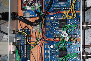
An amplitude regulated quadrature oscillator is the starting point of the circuit. The sine and cosine outputs are passed to a window detector that outputs a positive going pulse at each zero-crossing event. The pulses are used to clock-in the starting and stopping control signals and track the number of steps that a motor has made. The inverted cosine wave can be selected to reverse the motor's direction. The selected signals are then amplified and applied to a transistor follower output stage. For my purposes, a parallel port interface is used to control the motors and manage the signal switching.

Next steps

Next up, I'll take a look at Gerber format and a more in-depth look at CUPS. I'd like to make the controller directly accessible from File->Plot in KiCAD.

I'm also starting a full feature implementation using this circuit as the core. Will it use a microcontroller or an acre of TTL? Variable speed, limit switches, and closed loop control begin the feature list.

Sin_Mod_XY.jpg

An XY mode scope-grab of sine and ring modulator signals. How often do you get to use XY, anyhow?

JPEG Image - 94.35 kB - 06/23/2020 at 14:58

Preview
Download

Sin_Cos_Mod.jpg

Sine, cosine and ring modulator traces. Looks like I didn't manage to hold the camera perfectly still. Might also be time to clean the scope's screen, too.

JPEG Image - 97.70 kB - 06/23/2020 at 14:58

Preview
Download

SineDriver.tar.gz

Complete KiCAD project file set. Includes an optional parallel port interface that, when paired with a raw printer device in CUPS, you'll have user-land access to the motors. Updated: 22 Jun 2020

application/gzip - 13.26 kB - 02/17/2020 at 18:42

Download

Motor_Printer_2.rb

This is a simple app to convert some G-Code (G0, G1) to a stream of control characters for the breadboard controller. The "SETUP" section contains the variables to edit for specifics of your system. Updated: 22 Jun. 2020

application/x-ruby - 14.22 kB - 03/12/2020 at 18:07

Download

Breadboard.jpg

It might not be pretty, but the motors are controllable from the command line.

JPEG Image - 131.03 kB - 02/17/2020 at 20:13

Preview
Download

View all 7 files

  • 1 × lm324 Amplifier and Linear ICs / Operational Amplifiers
  • 1 × lm393 Amplifier and Linear ICs / Comparator ICs
  • 2 × sn74ls74 Logic ICs / Decoders, Encoders, Multiplexers, Demultiplexers
  • 2 × cd4066 Electronic Components / Misc. Electronic Components
  • 3 × lm358 Amplifier and Linear ICs / Operational Amplifiers

View all 6 components

  • ​Polarity Problem​?

    Darrin B06/22/2020 at 21:55 0 comments

    In the log entry titled "Does it have to be pretty?", I mention the Polarity0/1 signals. The present ring modulator based system does not provide them. They are not used by the parallel interface, but would likely be handy to have available for other interfacing schemes.

    I may restore the signals, I'm just not feeling motivated enough to make changes the breadboard right now.

  • Phase Matters

    Darrin B06/22/2020 at 15:02 0 comments

    It took a while, but I eventually noticed that the modulator's output signal zero-crosses had little in common with the sine-cosine zero-crosses. If only there was a way to shift them a little bit...

    Oh, right. Analog, sine waves, phase shift! Only 45 degrees is needed, this shouldn't be too difficult. Many simulations later, I changed a few resistor values and added two capacitors and now the zero-crosses are all lined up.

    The updated schematic/KiCAD project has been uploaded.

  • Analog Amusement

    Darrin B06/15/2020 at 17:52 0 comments

    In a very early incarnation of this circuit, the motors would take two steps in response to a single cycle control pulse. That happened because, even though the sine signal was only switched on for a half cycle, the cosine made a polarity change during that half cycle. Eventually, I realized that I needed to trigger the switches whenever either the sine OR the cosine made a zero-crossing. Another pair of comparators and some diode-transistor logic was added to the circuit, and single stepping became the norm.

    A few weeks ago, a thread on .Stack reminded me of a fun bit of analog hardware called the ring modulator. It multiplies ine input signal by the other input signal, for a loose definition of multiply. Mostly, it is just interpreting the signs (not sines) of the inputs (sines). Whatever it does, the resulting output signal resembles a sine wave at twice the input frequency. With twice as many zero crossings, I need half the comparators. Out with the 339 quad, in with the 393 dual!

    I'll modify my build the next rainy day, then post an update. Stay tuned!

  • And... Done?

    Darrin B03/12/2020 at 19:37 0 comments

    Schematics and code are posted in the Files section. Had a dial indicator attached to an X axis cobbled together with regular threaded rod, with my PC moving it to and fro. The GCode had it moving +/-0.1 inches, and that is what it did.

    I'll check back from time to time while hacking, sawing and sometimes hacksawing things. I'm certain that there will be some updates, improvements, and comments to add to this project.

    Onward to the mechanical work! (First will be to replace the pictured threaded rod with Acme thread.)

  • Almost there

    Darrin B02/28/2020 at 01:45 0 comments

    Now this becomes a coding project. Converting G-Code to a stream of symbols, seems simple enough. There's also keeping phases synchronized for smooth stepping, and adjusting the output for direction changes. Much to be done, I'll be back.

  • Does it have to be pretty?

    Darrin B02/17/2020 at 19:52 0 comments

    Just posted the KiCAD schematic set. Oops, forgot to annotate a whole bunch of parts. I'll fix that. But, that is the circuit that is on my desk, spinning motors right now. The exception being R_Start1, it wasn't necessary for my oscillator to reliably start.

    If the parallel port isn't for you, the interface signals are fairly simple.

    NameIn/OutUsage
    DirectionInSelects either cosine or inverted cosine to control stepper direction.
    Run/Stop
    X/Y/Z
    InSwitches the sine and the selected cosine signal on or off.
    WINOutThis signal goes high each time the sine or cosine does a zero-crossing. It also clocks the flip-flops, so that signals switch at the end of a full step. Switch a motor on, count WIN pulses to track the number of steps a motor takes.
    Polarity
    Pol0/Pol1
    OutThese two signals indicate the state of the oscillator, and state of a motor's rotor when it is running. Coordinating the motor's state with these signals will allow for smooth starting and direction changes.

  • Completed, work in progress?

    Darrin B02/11/2020 at 22:43 0 comments

    The controller is completed, controlling motors from a PC's parallel port. I'm using a text editor to create the control strings that are then printed via CUPS. Yep, <File - Print>.

    The work in progress is that I'm cleaning up some aspects of the circuit, creating documentation and incorporating some improvements.

    The first improvement is the oscillator, Andrej Levstek] published research on Amplitude Stabilization of Quadrature Oscillators. The output of the current QO is 2.5Vp-p at 15Hz from an LM324 operating from a single 5V supply. Looking at the outputs with the scope's X-Y mode, I see a circle.

    I've posted a schematic, adapted for a stand-alone motor driver, in the files section.

  • Eww, distortion

    Darrin B02/11/2020 at 00:04 0 comments

    I hitched the scope up to the power op-amp version of the circuit, and found clipping! That had to end. Soon I built the diode regulated version found in a TI datasheet and added a power output stage to it. A schematic is in the project files area.

  • Turn, turn, turn

    Darrin B02/10/2020 at 00:59 0 comments

    One day, I just wanted to make a stepper motor rotate. A few TTL chips and a bunch of transistors later, it did.

    A few days later, Hack-A-Day published an article about sine-cosine drivers. I had to try it.

    What's the shortest path to sine-cosine? A quadrature oscillator made from a high-power dual op-amp. One chip, three resistors and three capacitors. No code, no drivers, no mail-order parts. Best of all, the chip was scavenged from a junked VCR.

    I was stunned at how smoothly the motor turned. This project begins...

View all 9 project logs

  • 1
    Gather Parts

    Nearly any four op-amps will serve in the role of the 324. I used a quad-pack to save a bit of space on the breadboard. Use whatever is handy. Whether it is a 324 or the latest micropower rail-to-rail model, the circuit can be adapted to work with it.

    I chose TTL over CMOS for the flip-flops, mostly because I have lots of TTL. 74C/74HC would be a good substitute. If you have 4013s, the 5V regulator and a few pull-up resistors can be removed. Keep in mind, you may need level shifting in a few places.

    The output needs a bit more customizing, depending on your steppers. The 358's output current is a bit limited, so discrete transistors will limit the output to somewhere around 0.5A at about 7V RMS with a dual 12V supply. Darlington transistors will all but eliminate output current limitations. The output voltage will max-out at about 9V RMS with a dual 15V supply.

    The most exotic part is probably the 4066. Still, it was sold at Radio-Shack. Just rummage around, you'll probably find them still in their original blister package. The 4016 can be dropped in without changing the circuit.

  • 2
    May your oscillator oscillate

    The first steps only need 5V, the source is up to you.

    Next, find a 2.0V zener diode. Or do what I did, use a LED that has a forward voltage drop around 2V at 10mA. This LED will become the virtual ground for the oscillator. The asymmetric power supply for the LM324 is intentional, allowing for nearly equal positive and negative voltage excursions before clipping sets in. The next LEDs you'll need are a pair that drop about 1.8V at just 1mA. This pair limit the oscillator's output, keeping it out of clipping.

    When the oscillator is ready for testing, hit the power switch. Check that LED (D1) for 2V, +/- 10%. (The oscillator sometimes takes a few seconds to start up.) Now check the sine and cosine outputs. If there is clipping R2 and R3 can be adjusted to compensate, or you can try some other LEDs. Both sine and cosine signals should be very close in amplitude.

    If your oscilloscope supports X-Y mode, set both inputs for the same volts/division and put the probes on the sine and cosine outputs. You should see a circle. A flat spot means that there's still some clipping. A diagonal ellipse could be either an amplitude problem, or the scope inputs are mis-set. Depending on which probe is on which signal, the circle could be drawn clockwise or counter-clockwise.

    While we're here, check the inverted cosine output. Channel-invert the input and overlay it with cosine, the signals should match.

  • 3
    Windows

    3a) The ring modulator has a phase shift on its input, if you run the oscillator at a frequency other than 15Hz, you will need to adjust R10,R11, C102, C103. You want to the sine and cosine at the same time the ring modulator's output zero-crosses.

    3b) Next up is the window detector. It has to do a few things TI tells us to avoid, like using a breadboard and applying a slowly varying input signal. Adding hysteresis didn't help enough and it delayed the timing of the output pulses. The solution was to use low value resistors for the input and put capacitors across each input pair.

    Not much to check here, there should be a pulse where the either the sine or cosine crosses the axis and that it isn't oscillating or ringing. Keep in mind, there are two different 'grounds' in use now. The sine and cosine signals are referenced to AGND, while the WIN signal is referenced to Gnd.

View all 8 instructions

Enjoy this project?

Share

Discussions

Similar Projects

Does this project spark your interest?

Become a member to follow this project and never miss any updates