 Supplyframe DesignLab
Problem
How might we decrease the occurrence of marine species entanglements with fishing gear and decrease ghost gear creation, while making the commercial fishing process more intelligent for fisheries?
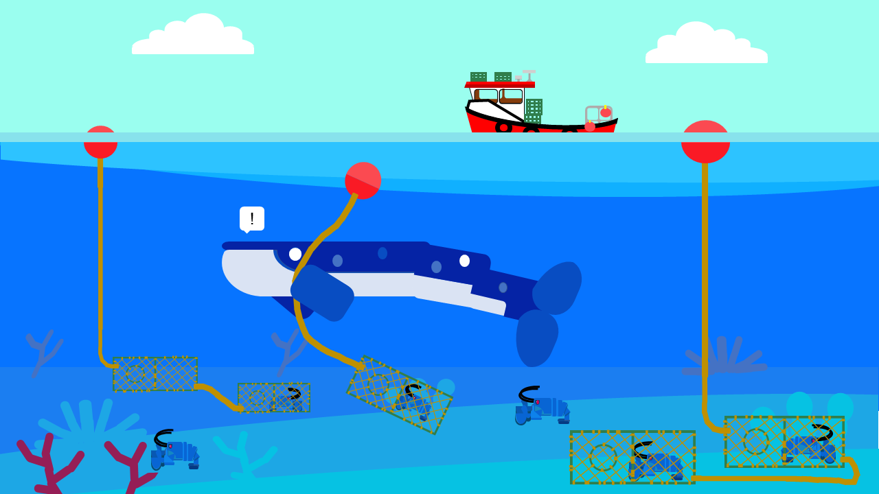
Our main goal is the prevention of gear loss. A great solution not only benefits the environment but also benefits the fishers, they can avoid the income losses that ghost gear creates and also benefit from an intelligent gear that collaborates to improve their efficiency.
To achieve our goal we define a concept of operations the includes an intelligent buoy that allows fishers to track the position of the traps, and a ropeless mechanism that prevents entanglements.
Solution
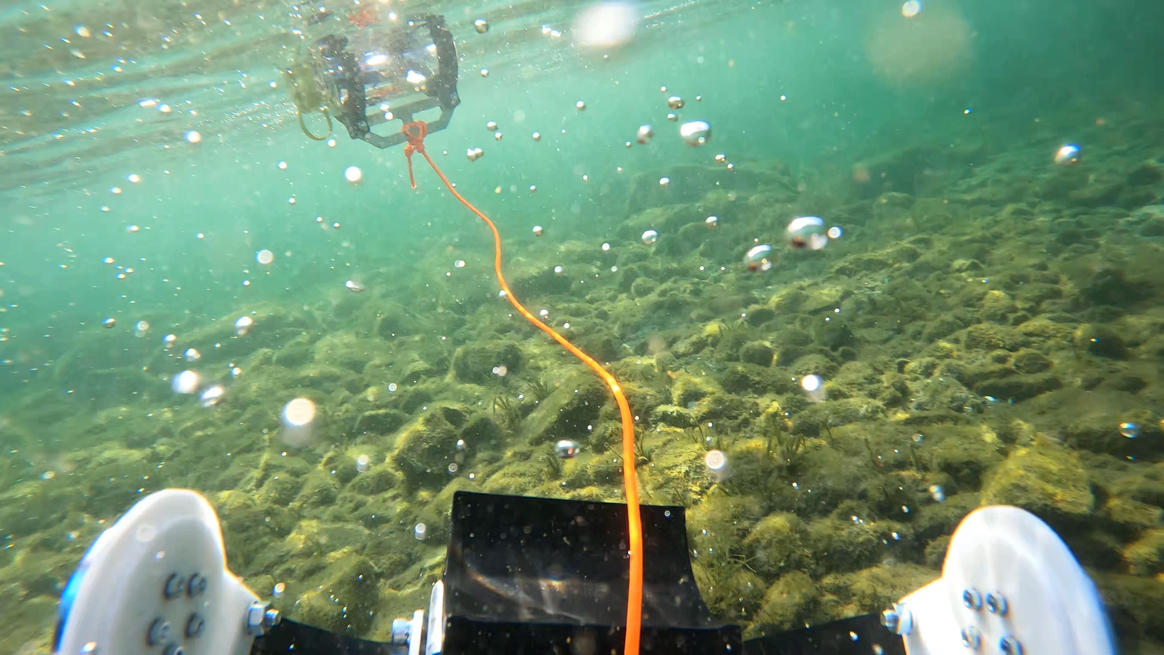
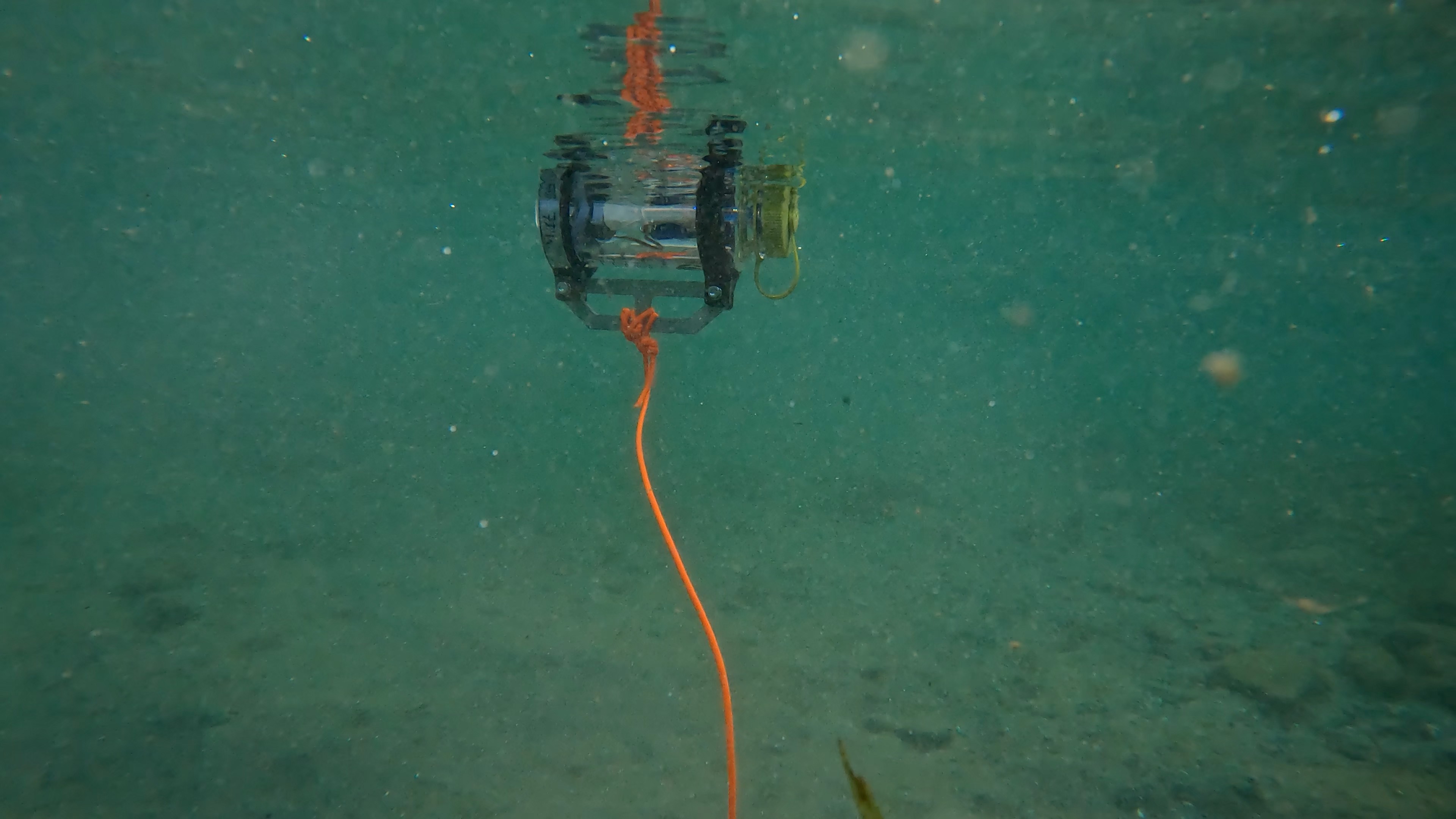
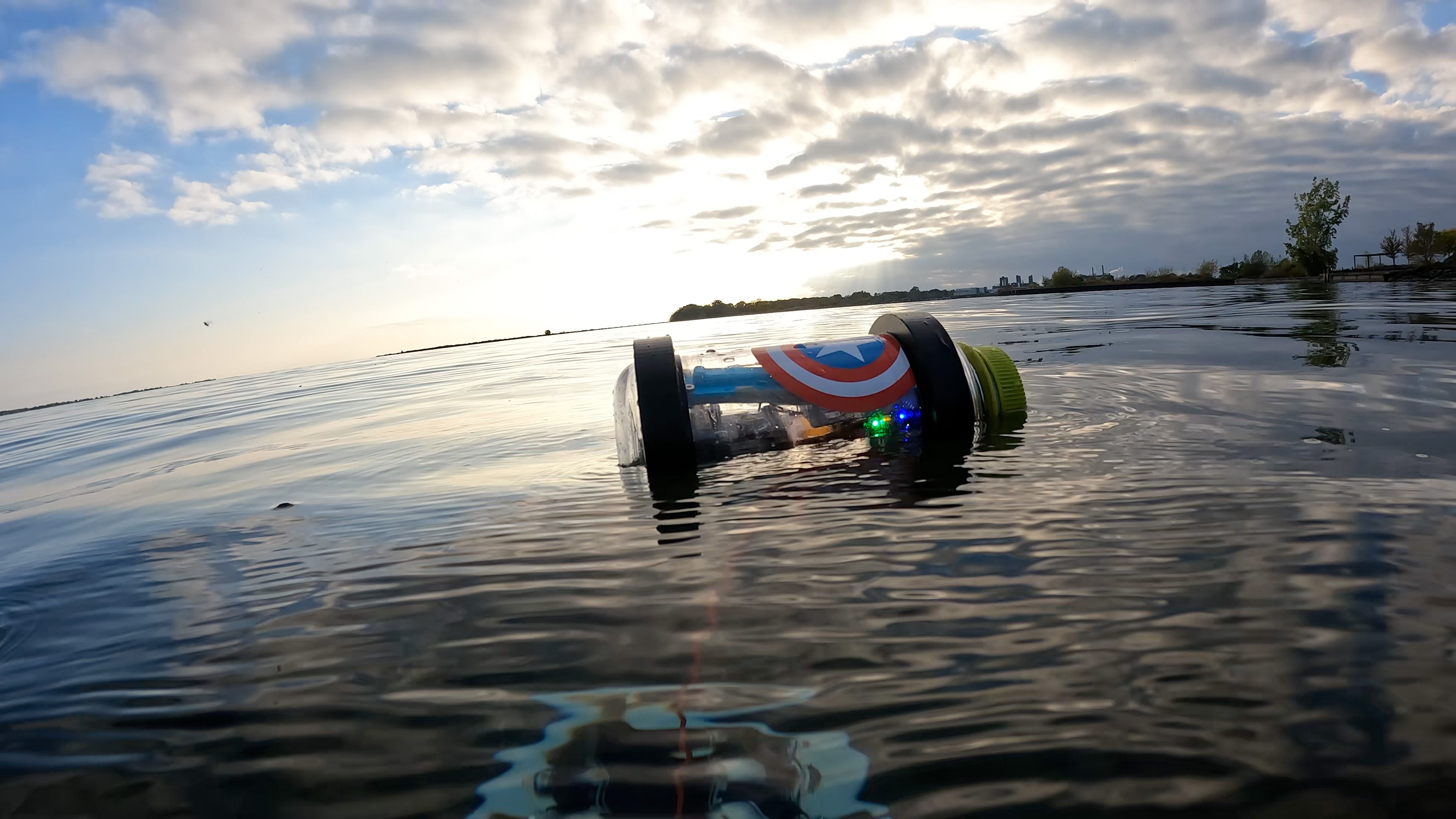
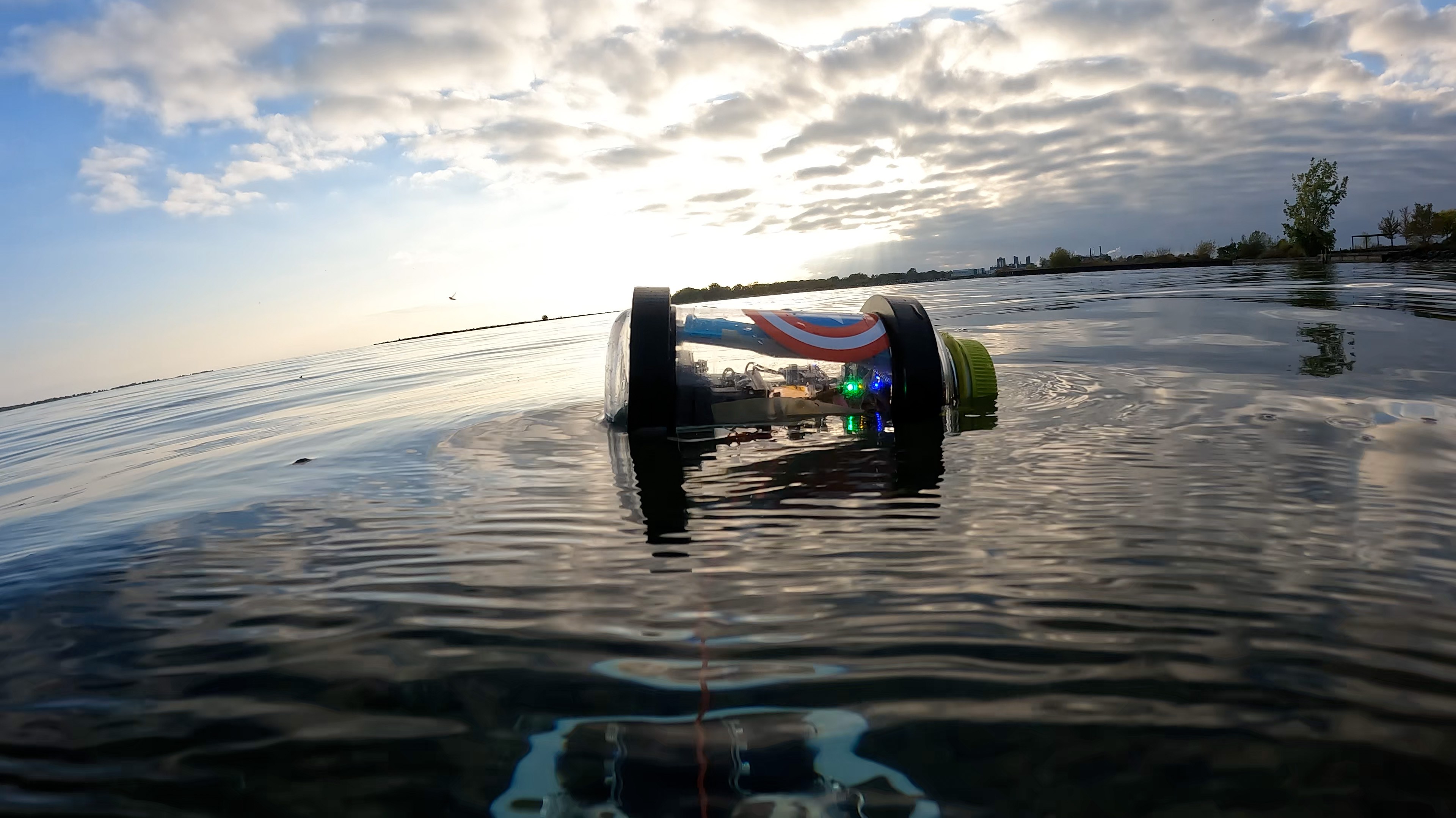
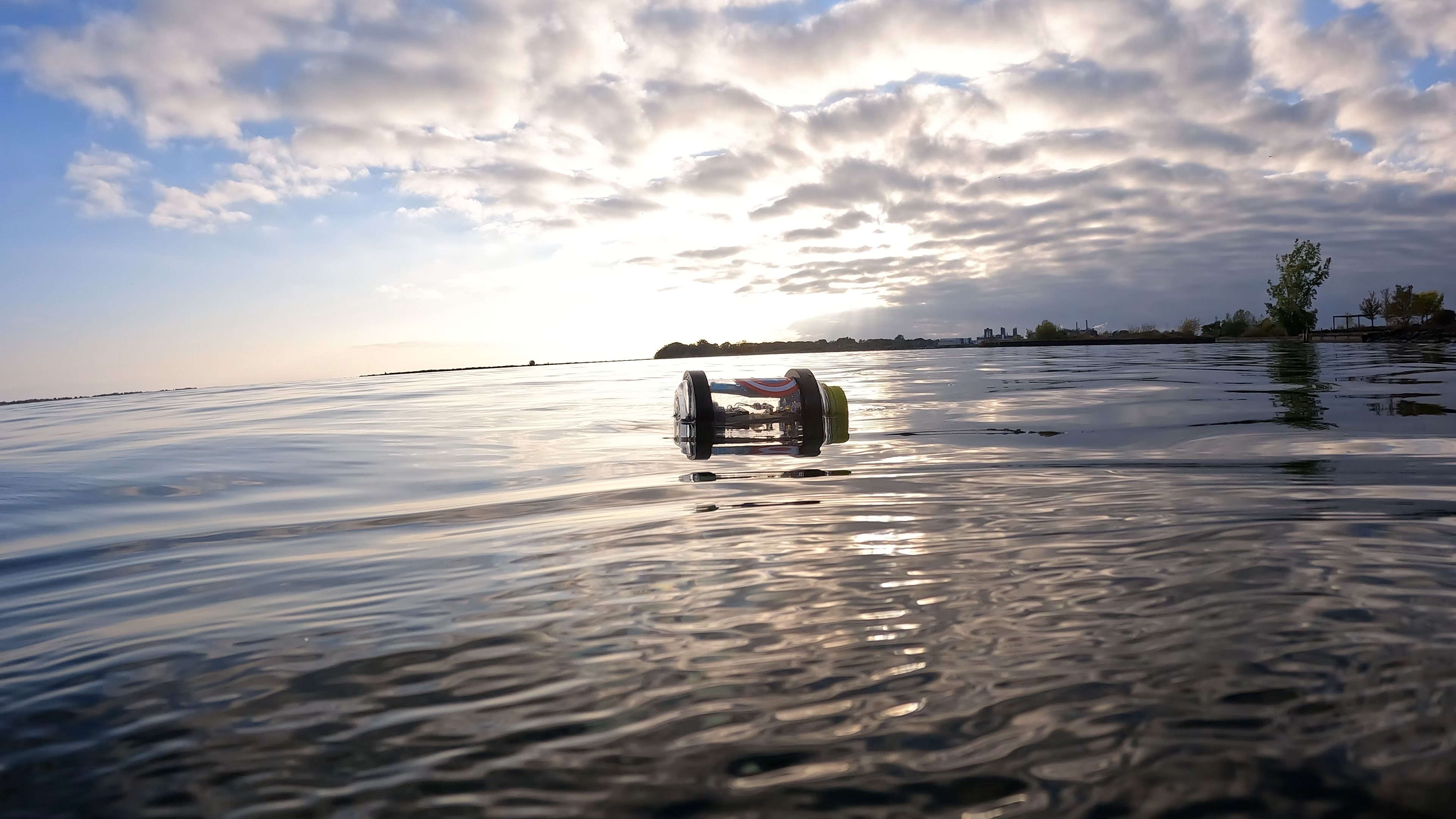
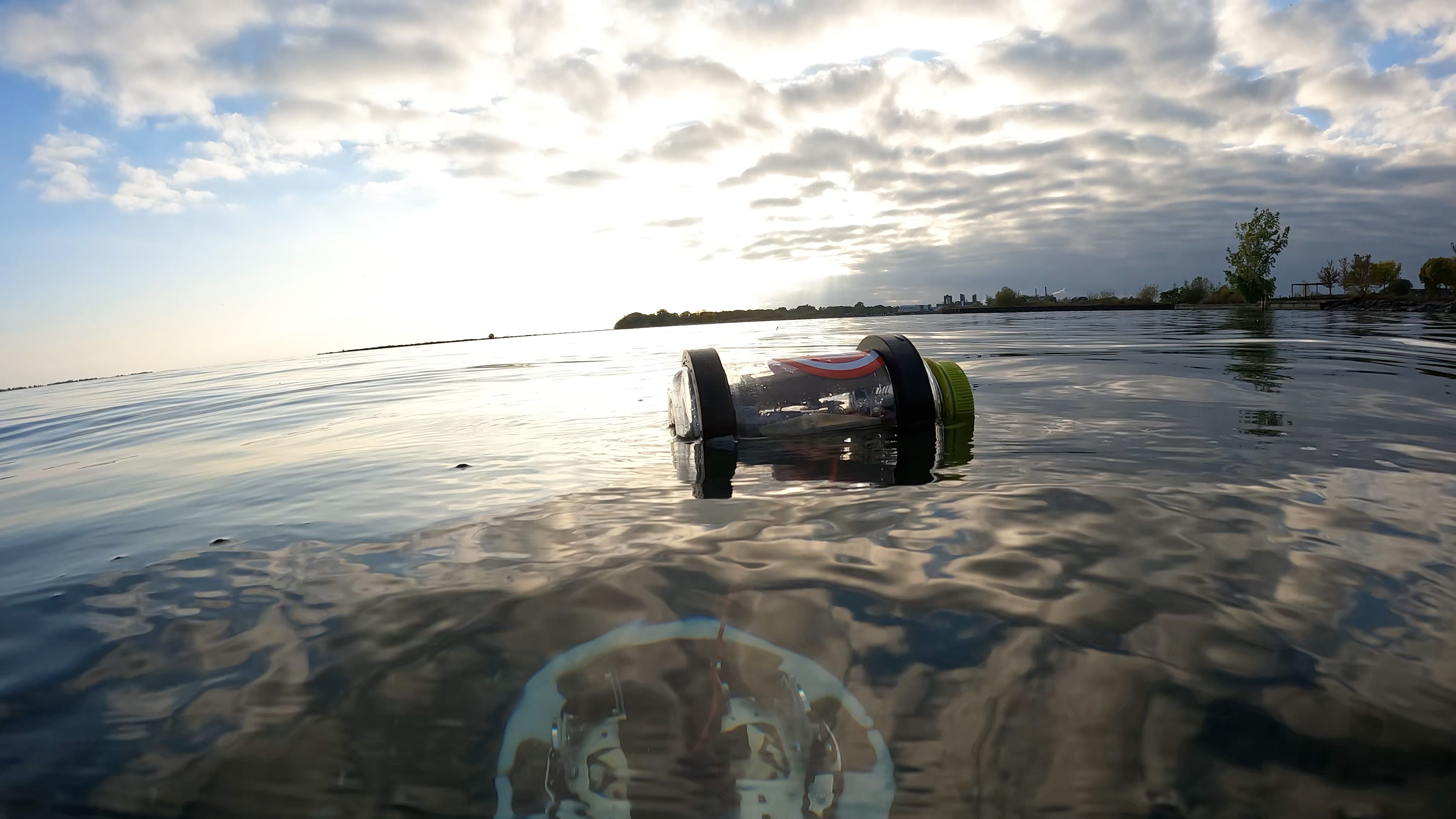
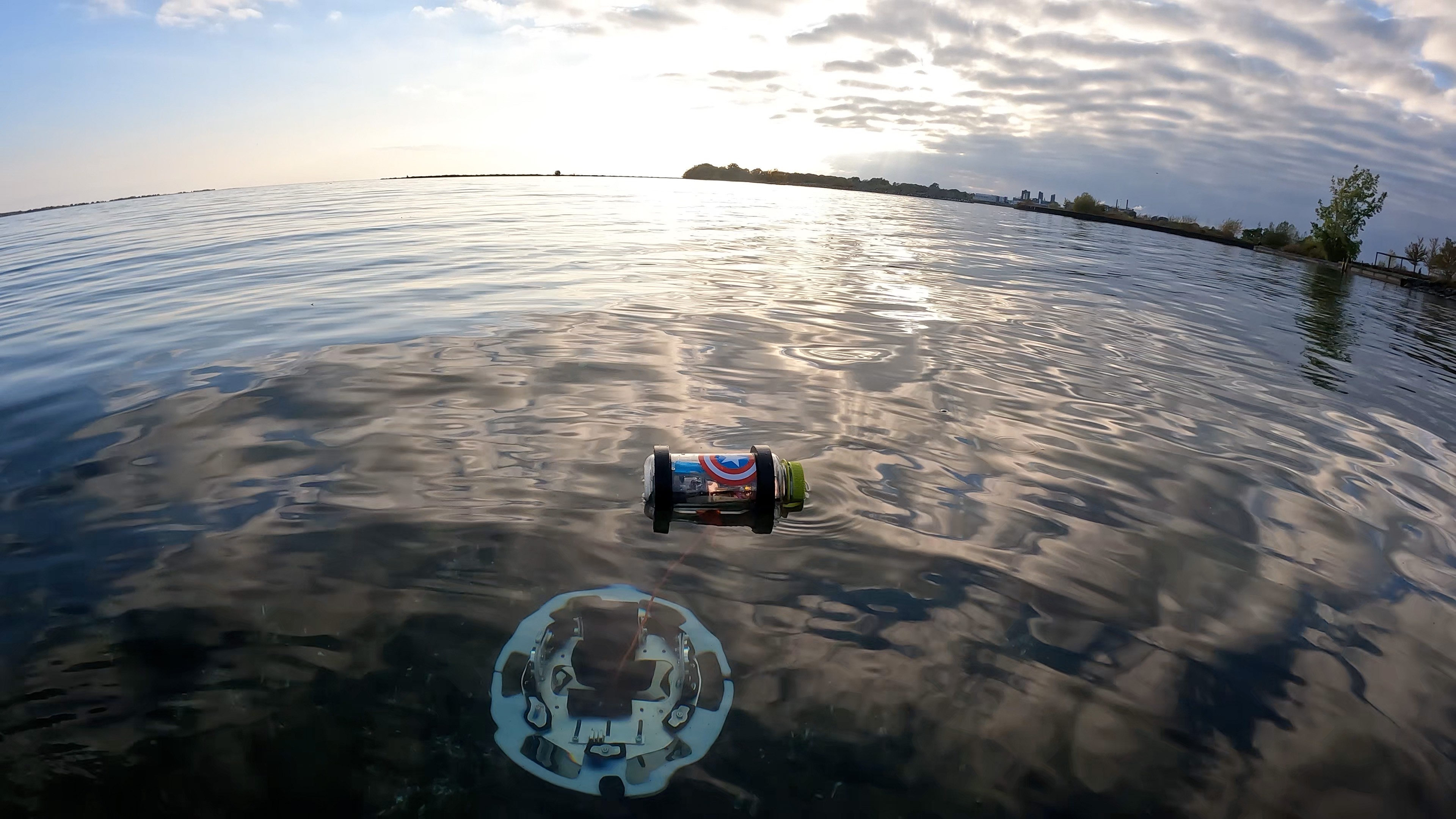
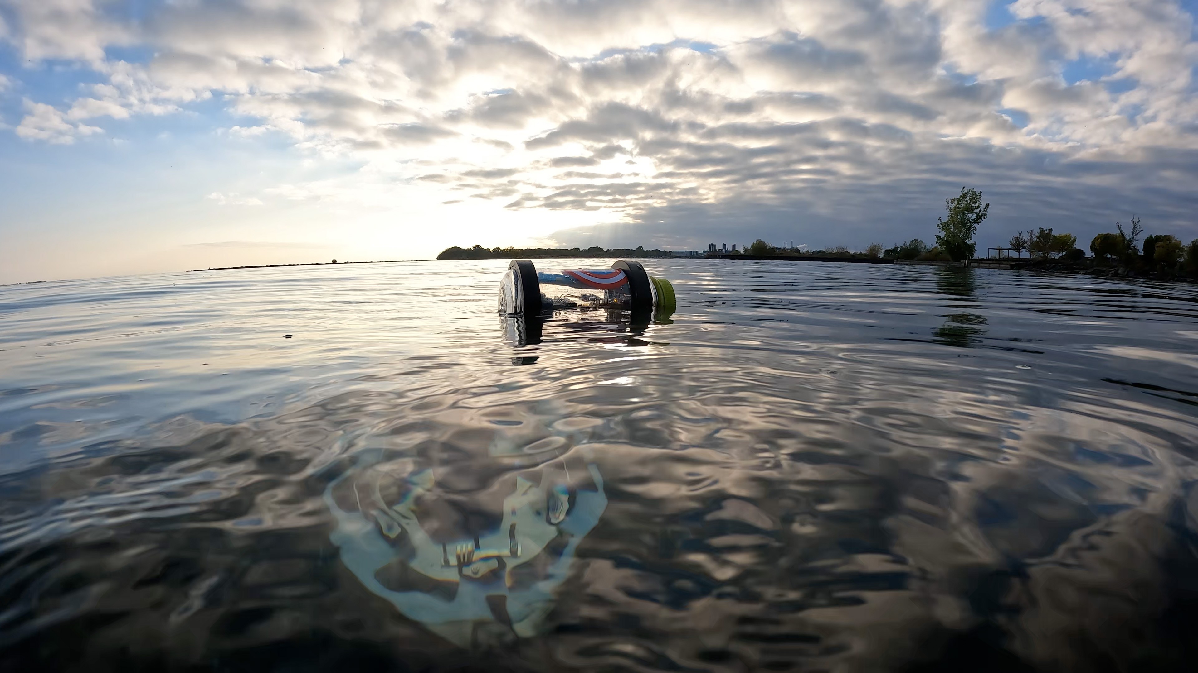
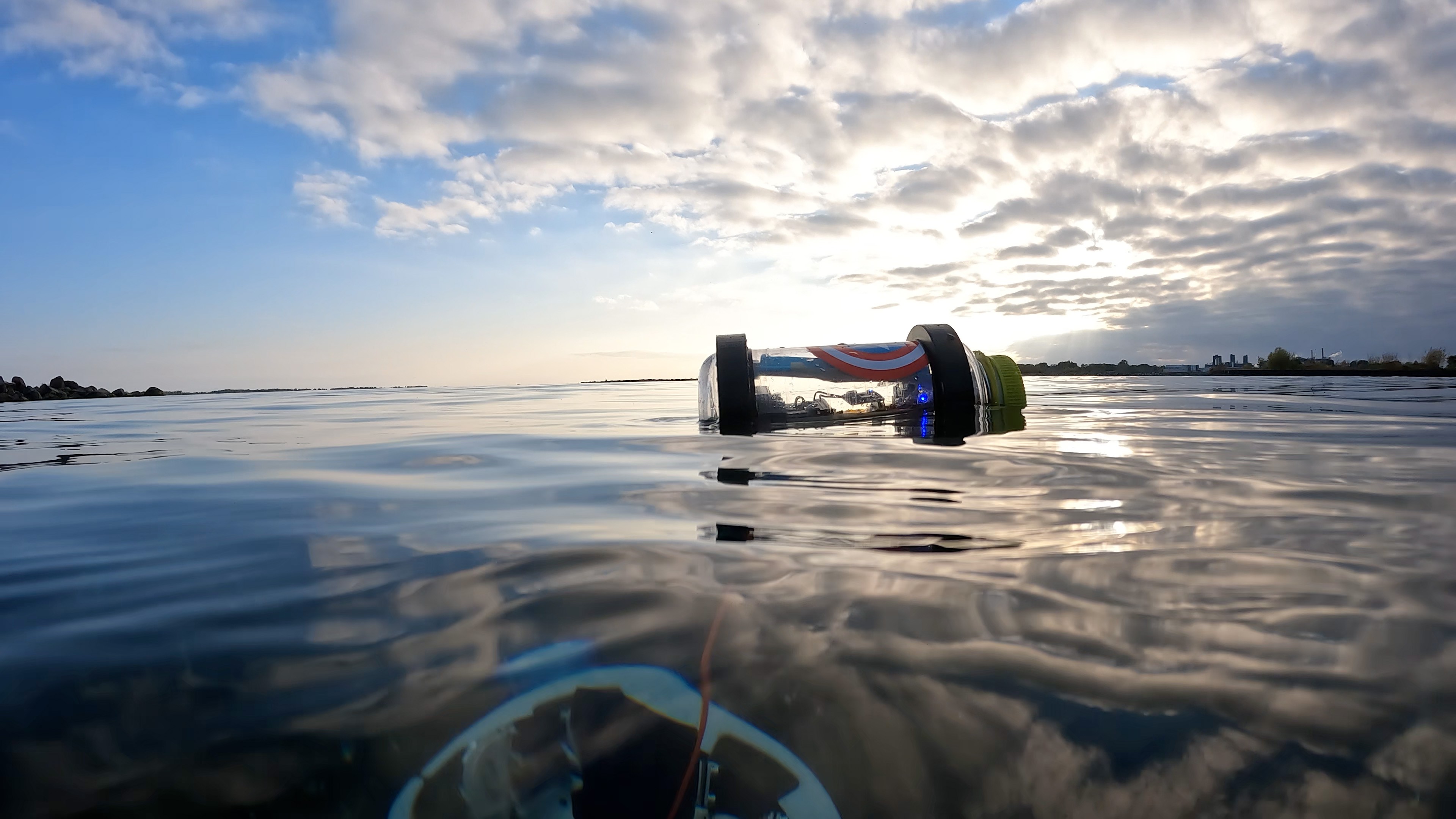
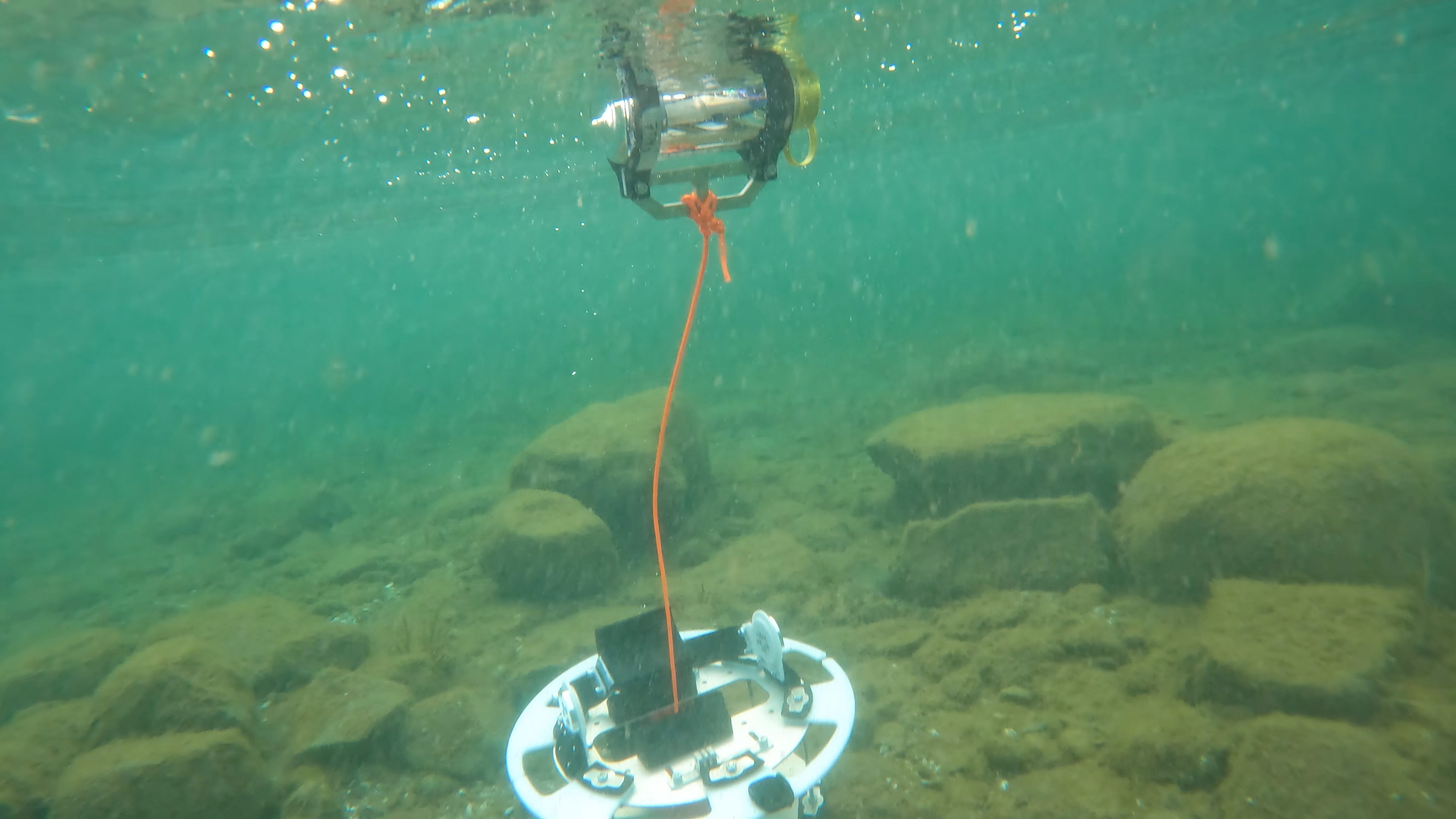
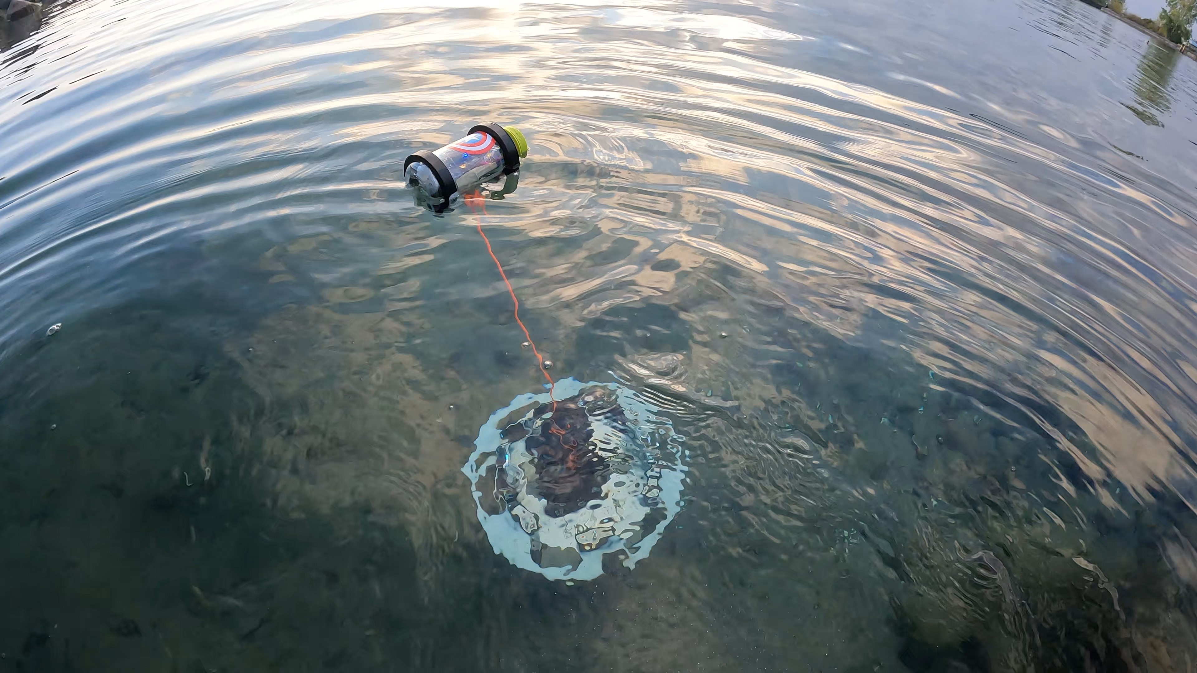
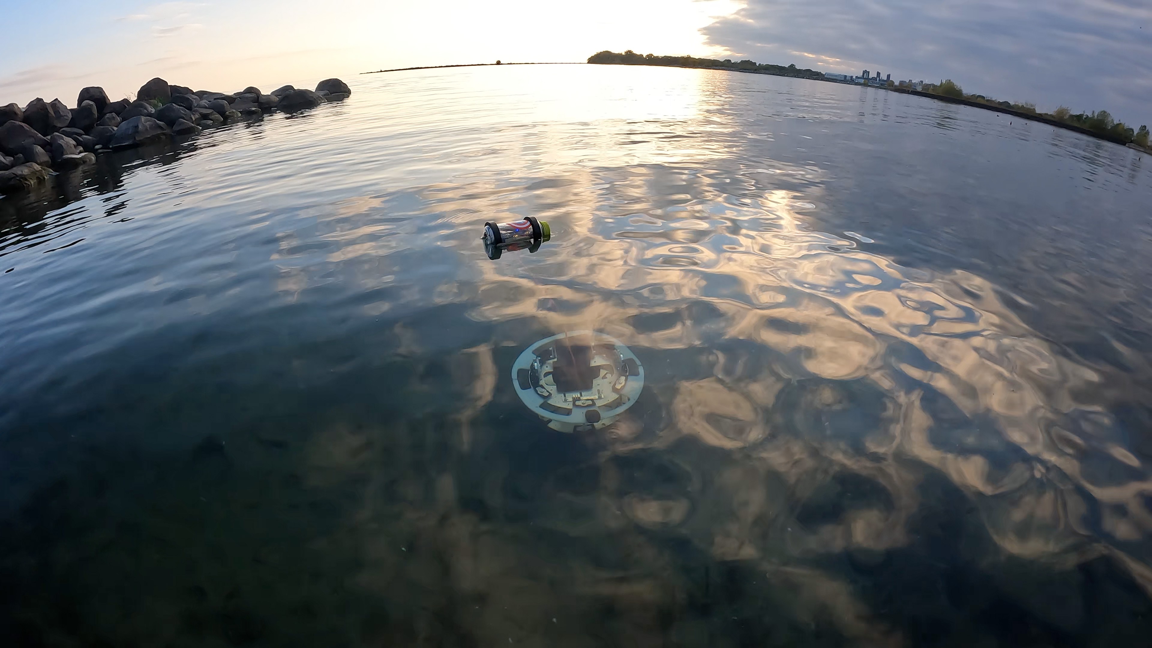
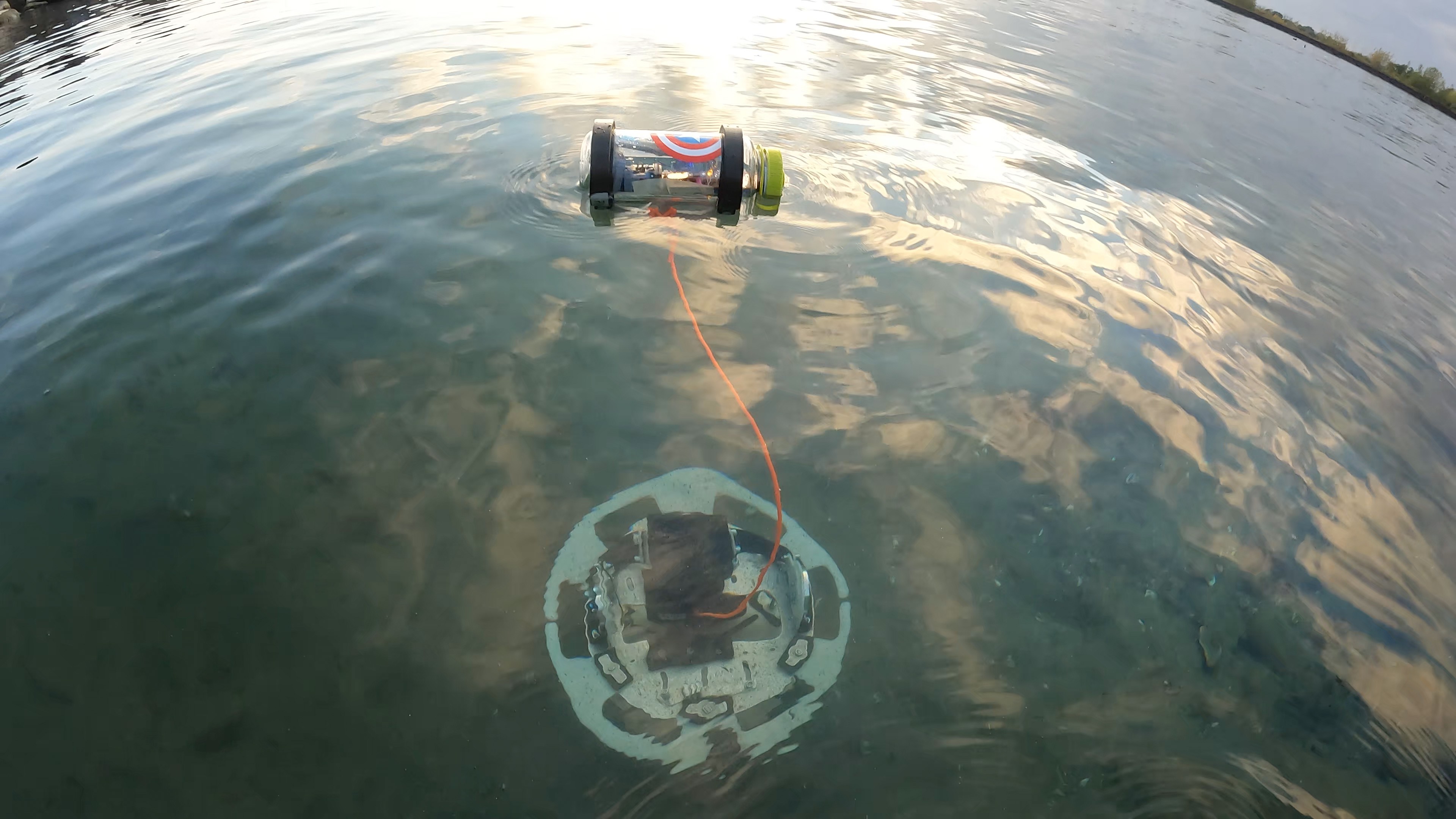
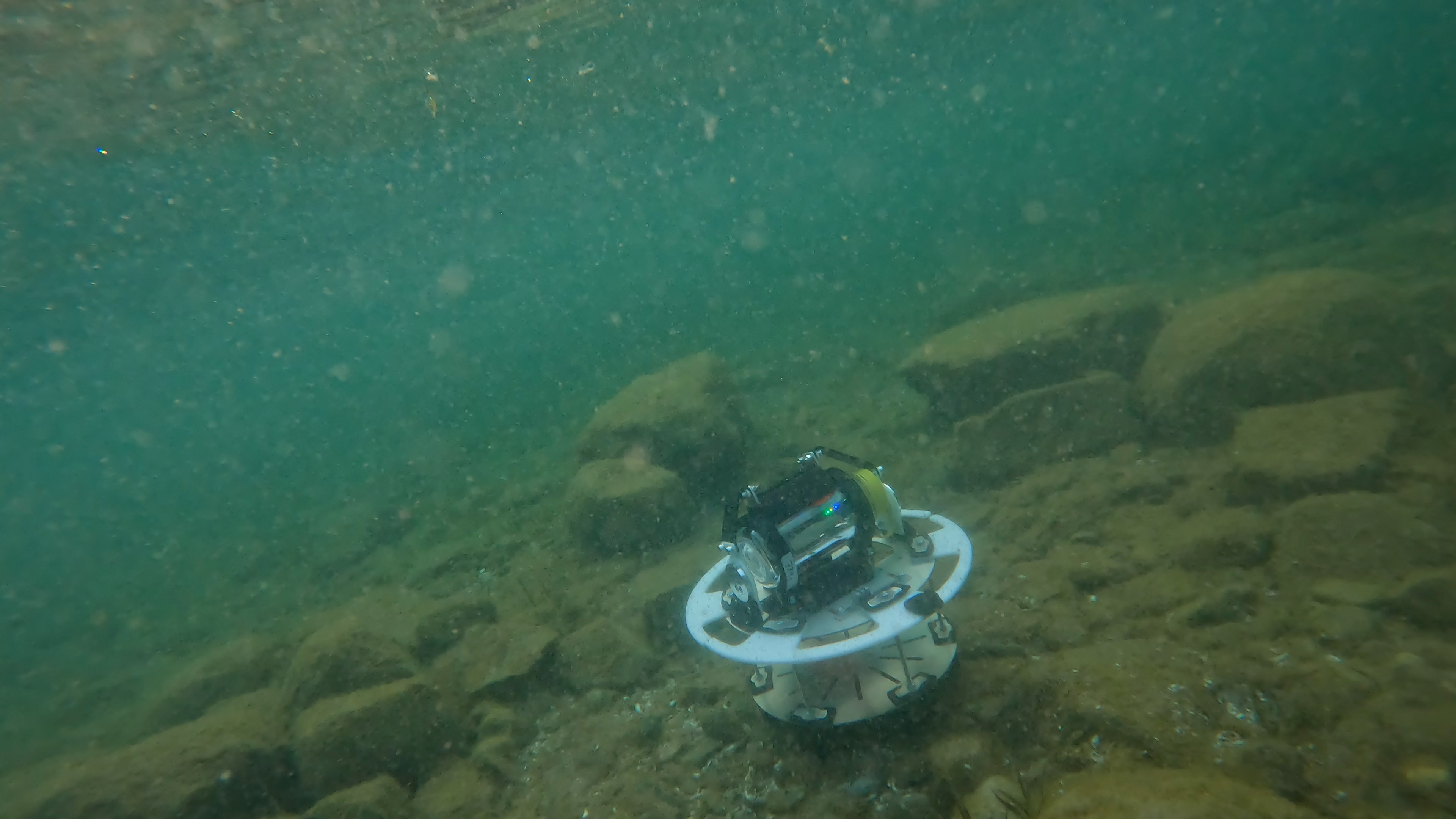
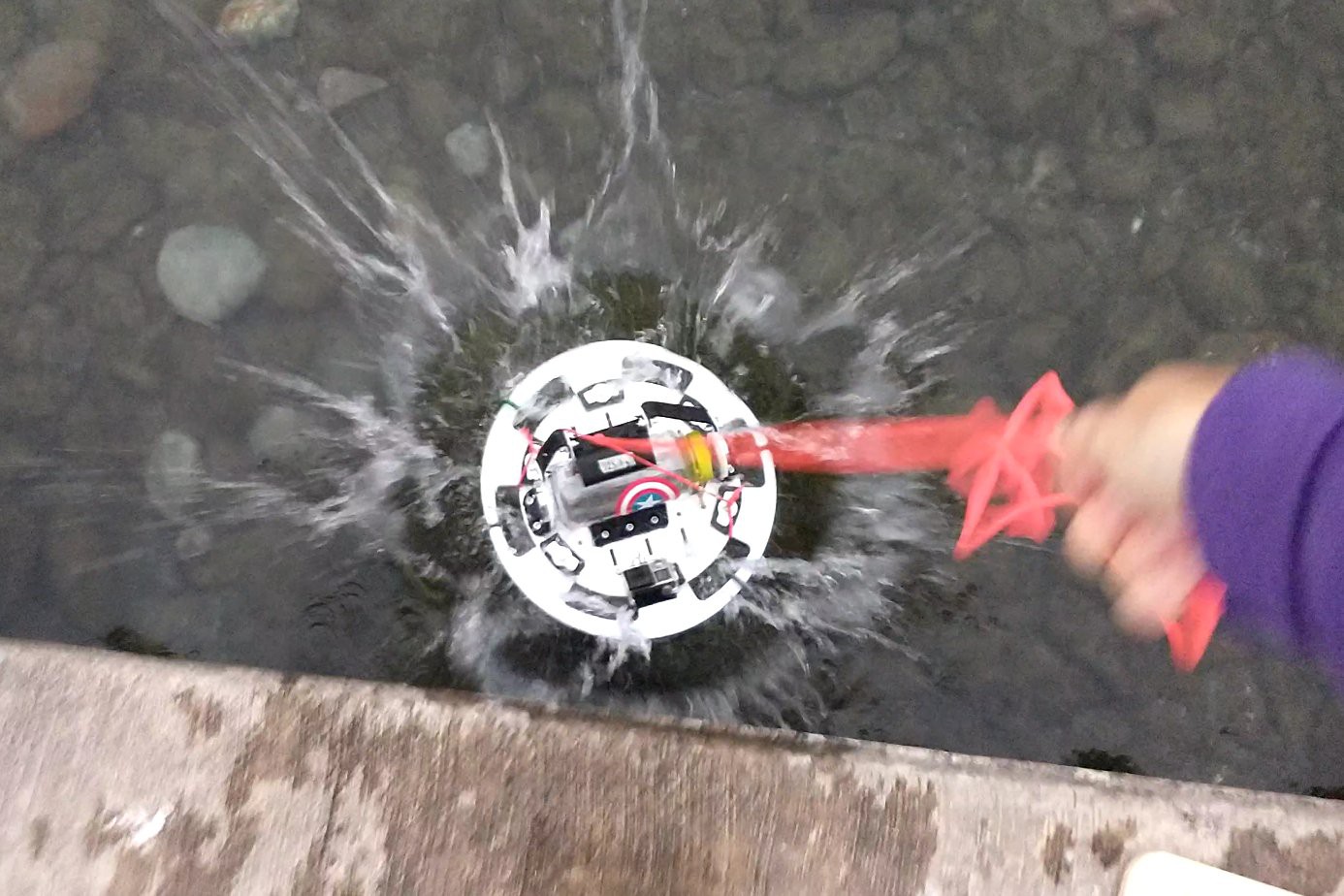
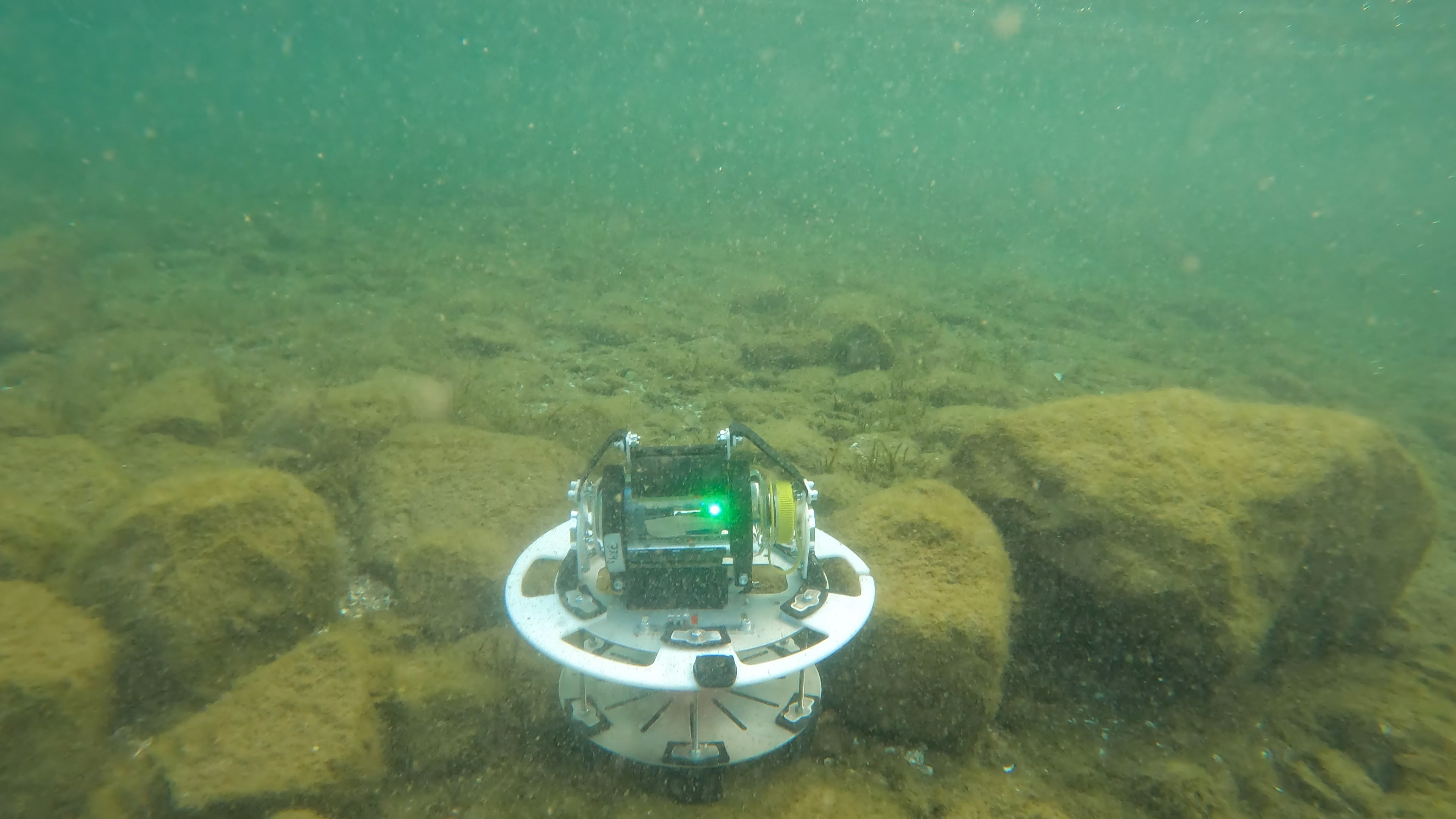
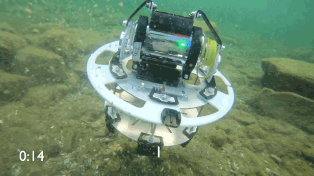
EJA robot is a ropeless fishing system - the buoy is launched to the surface only after certain sensor data
Electronics
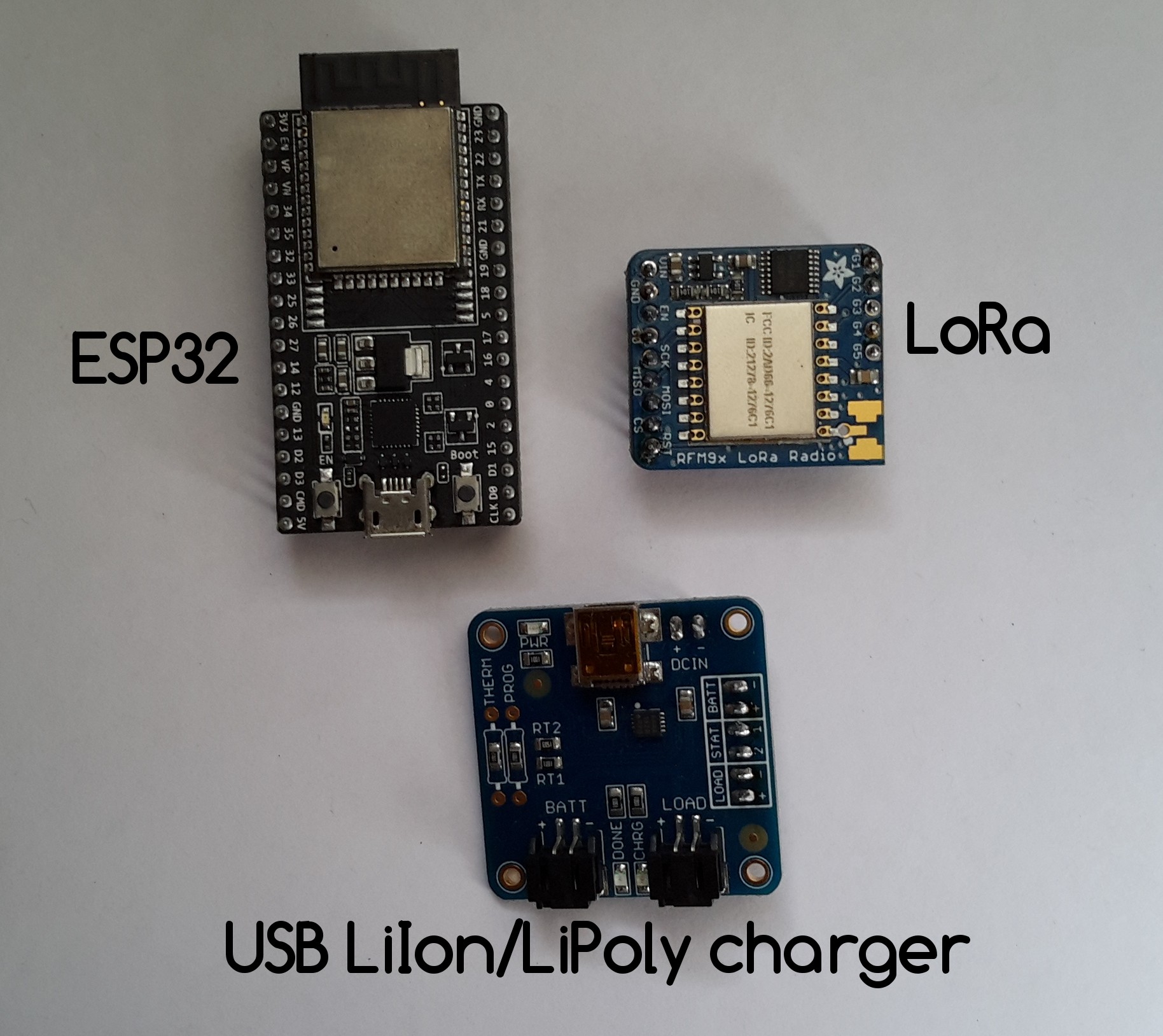
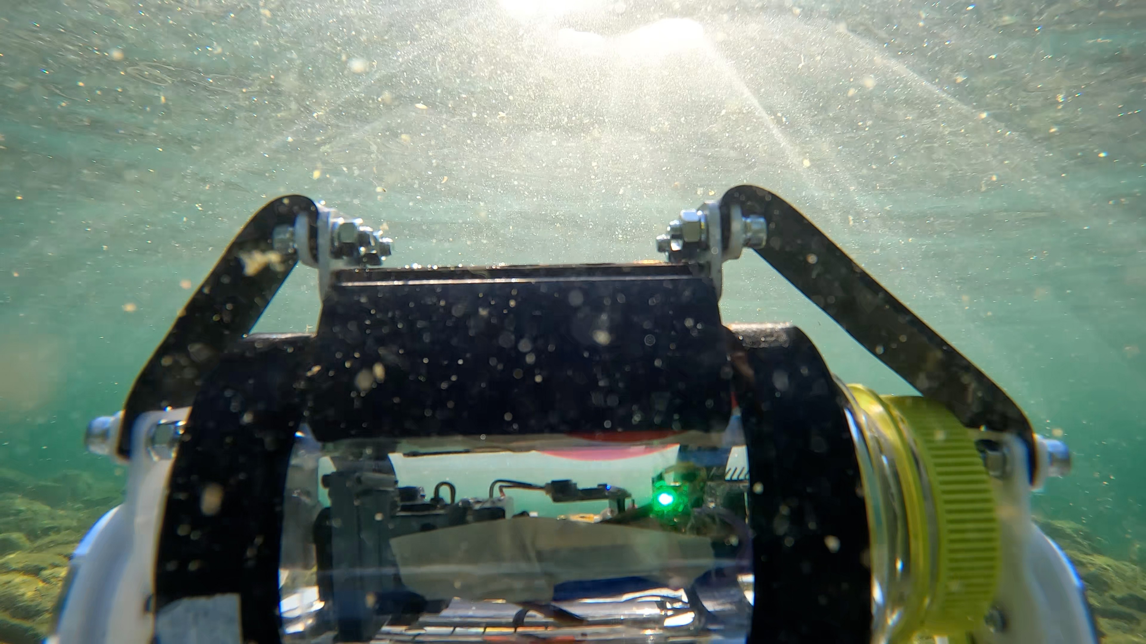
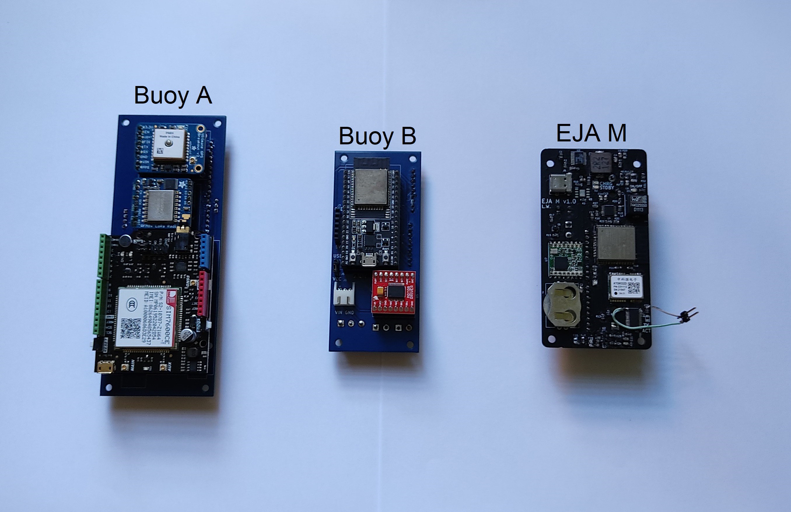
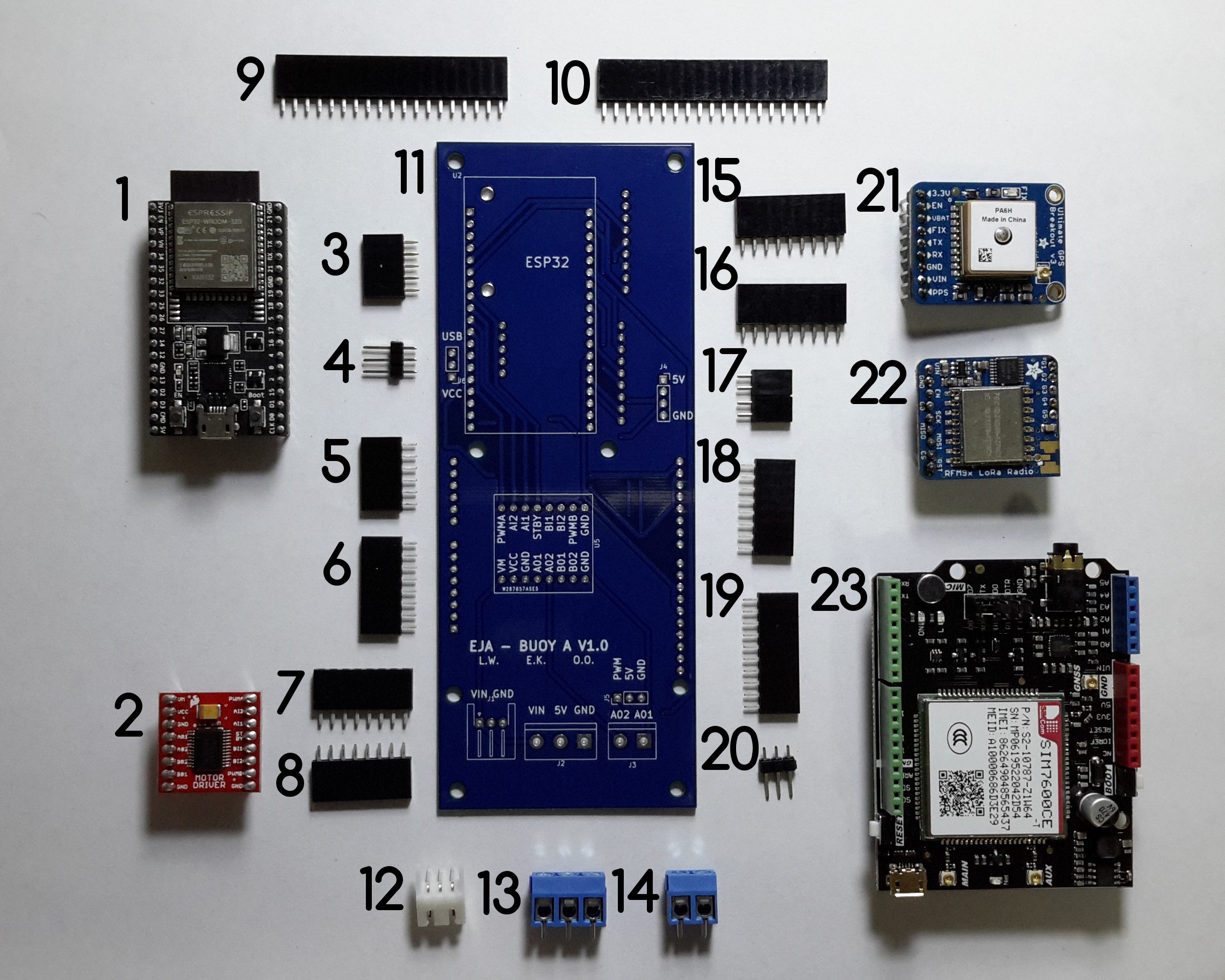
This project contains the design of 2 electronic devices (from left to right in the following image): the Intelligent Buoy and the Onboard Gateway.
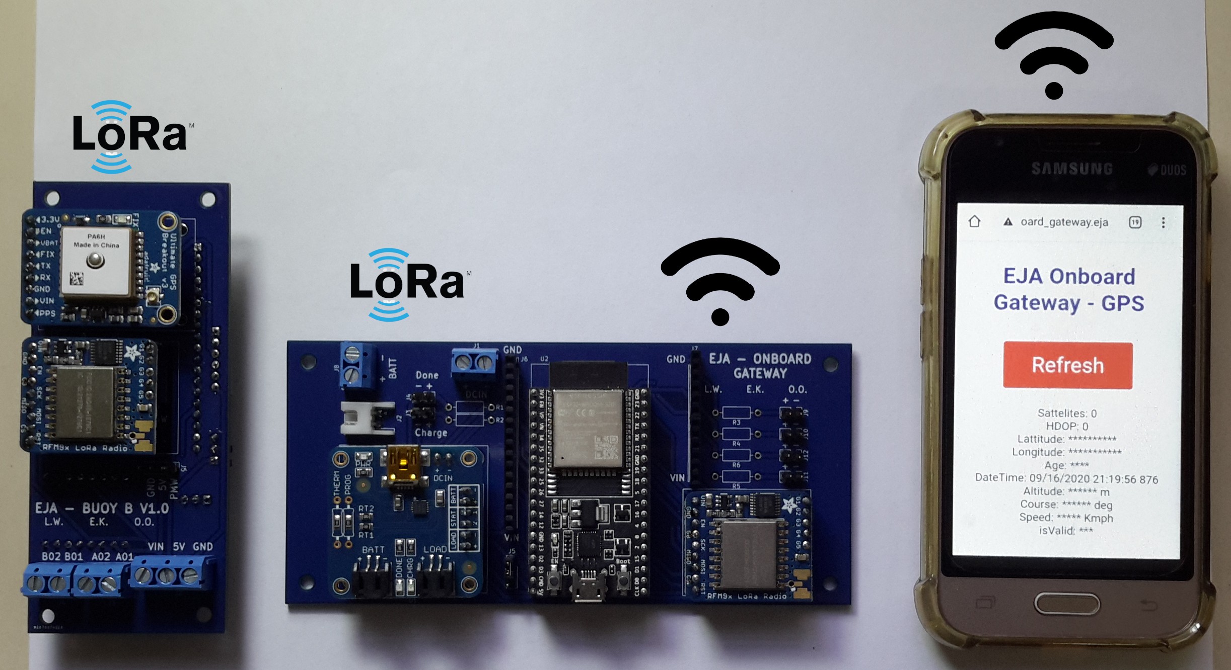
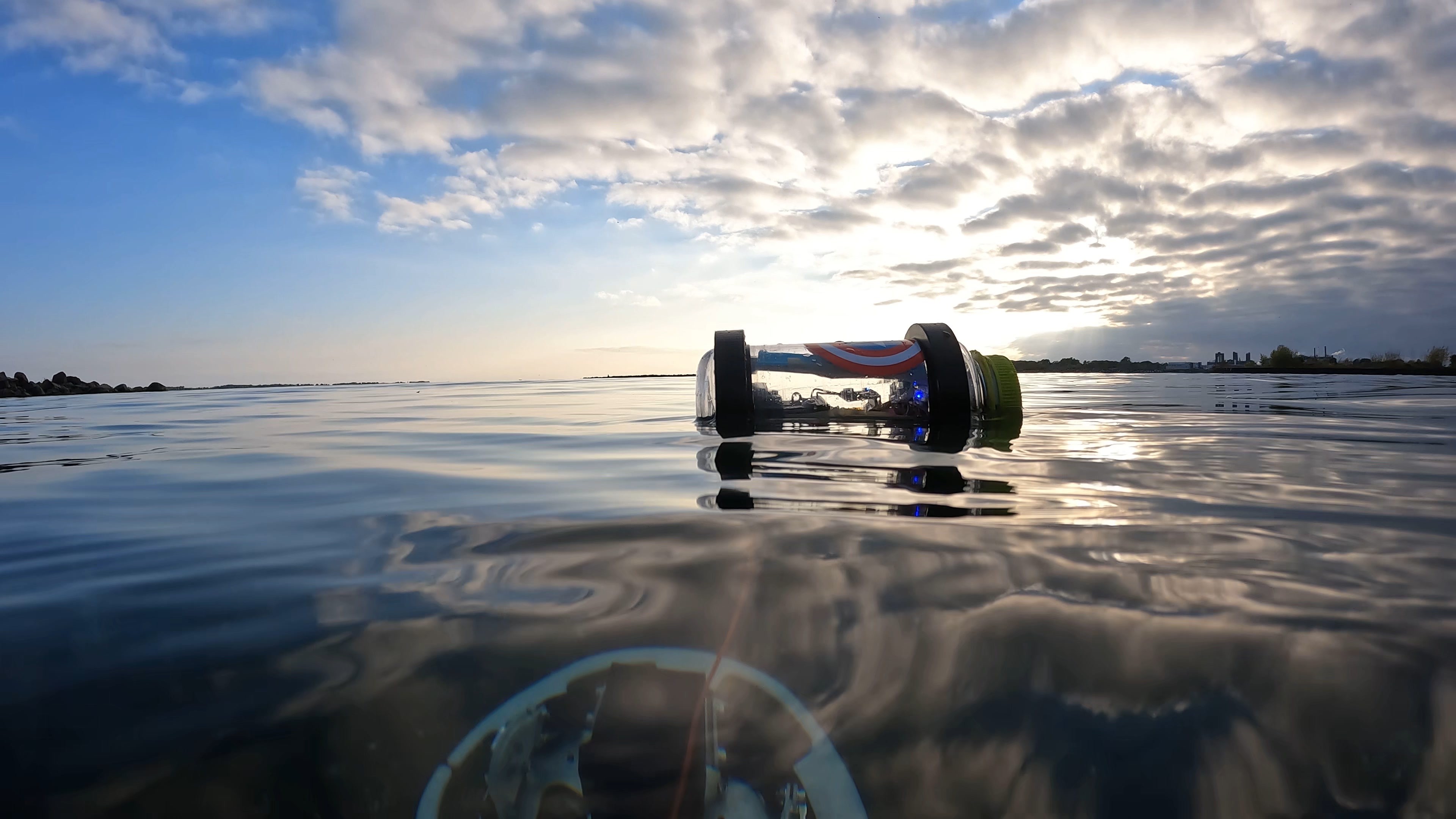
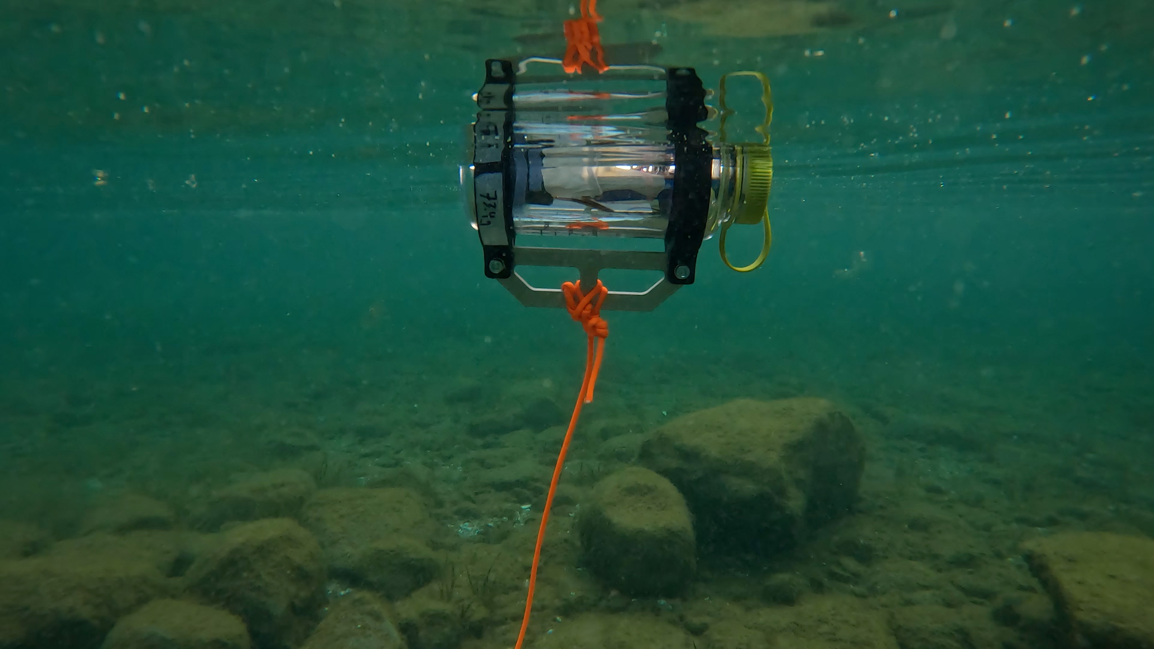
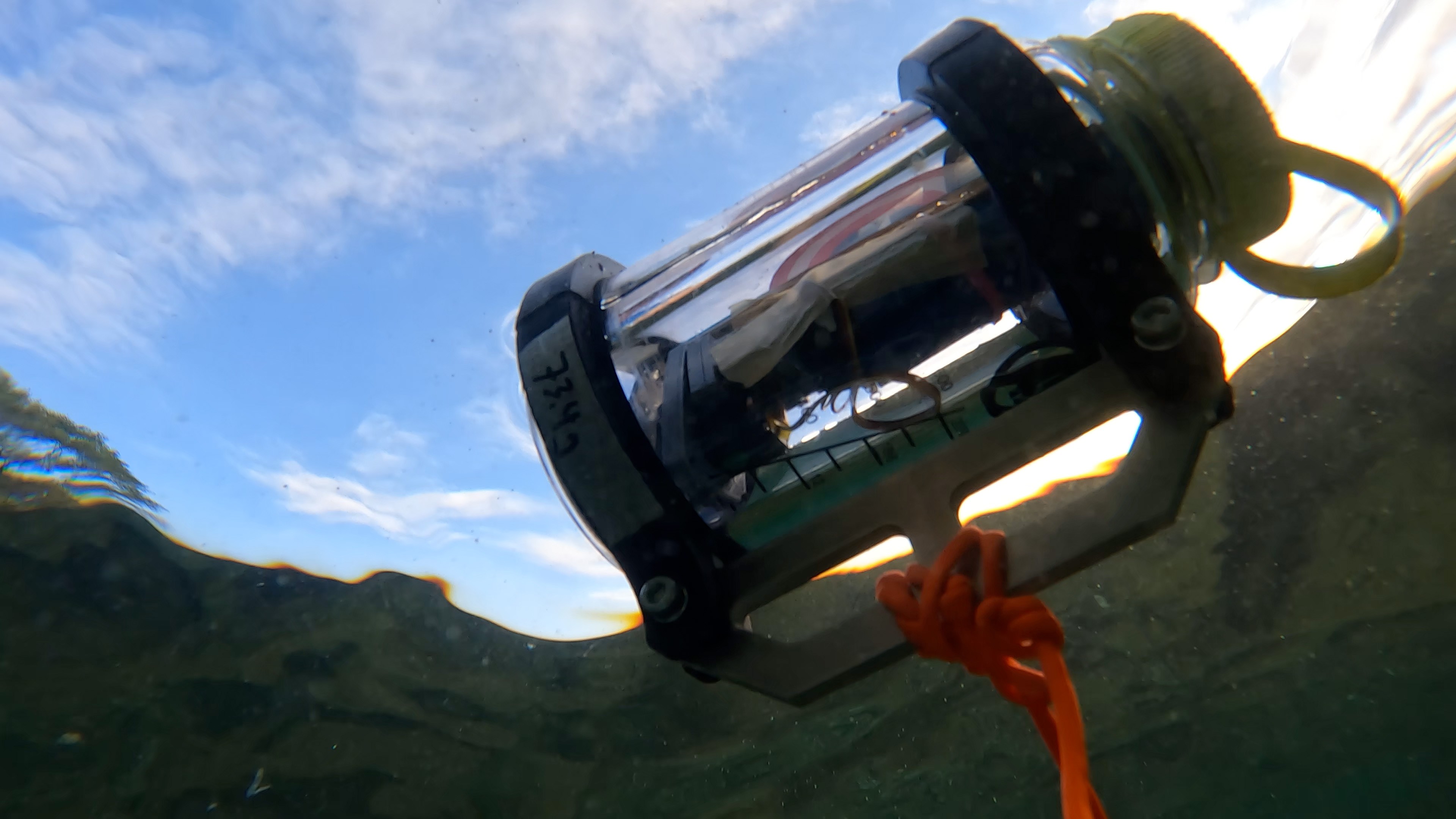
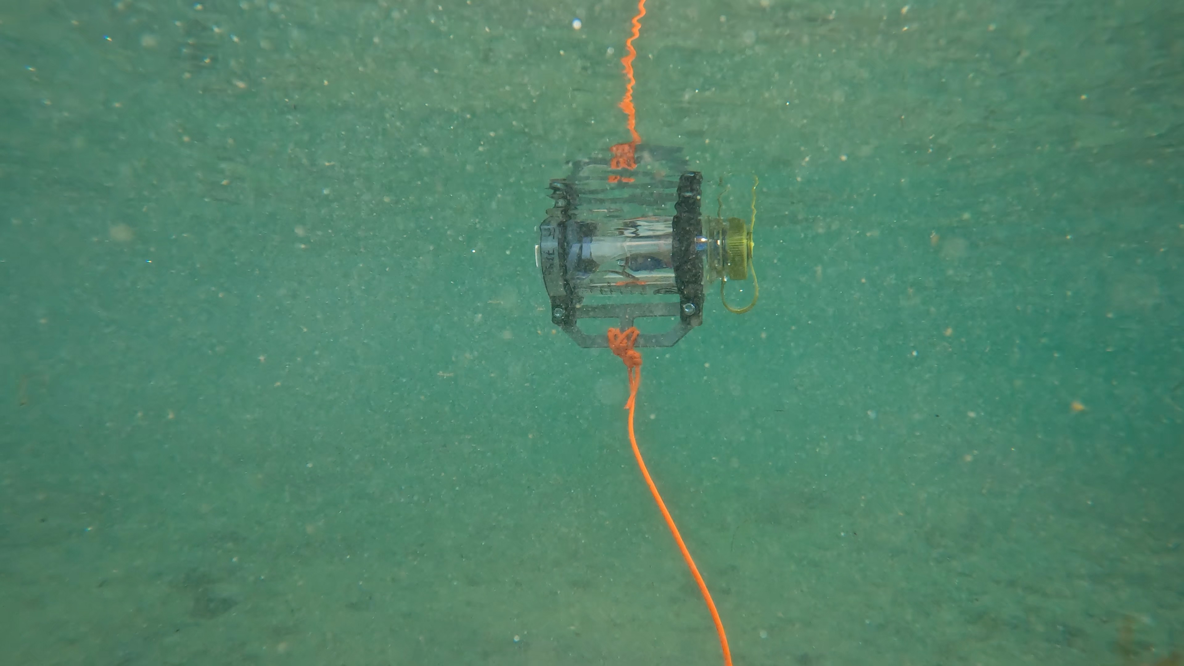
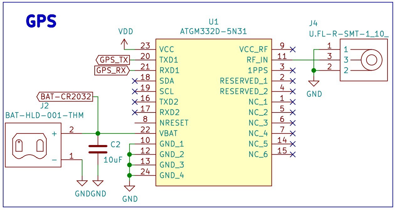
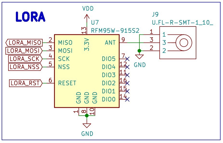
Intelligent Buoy
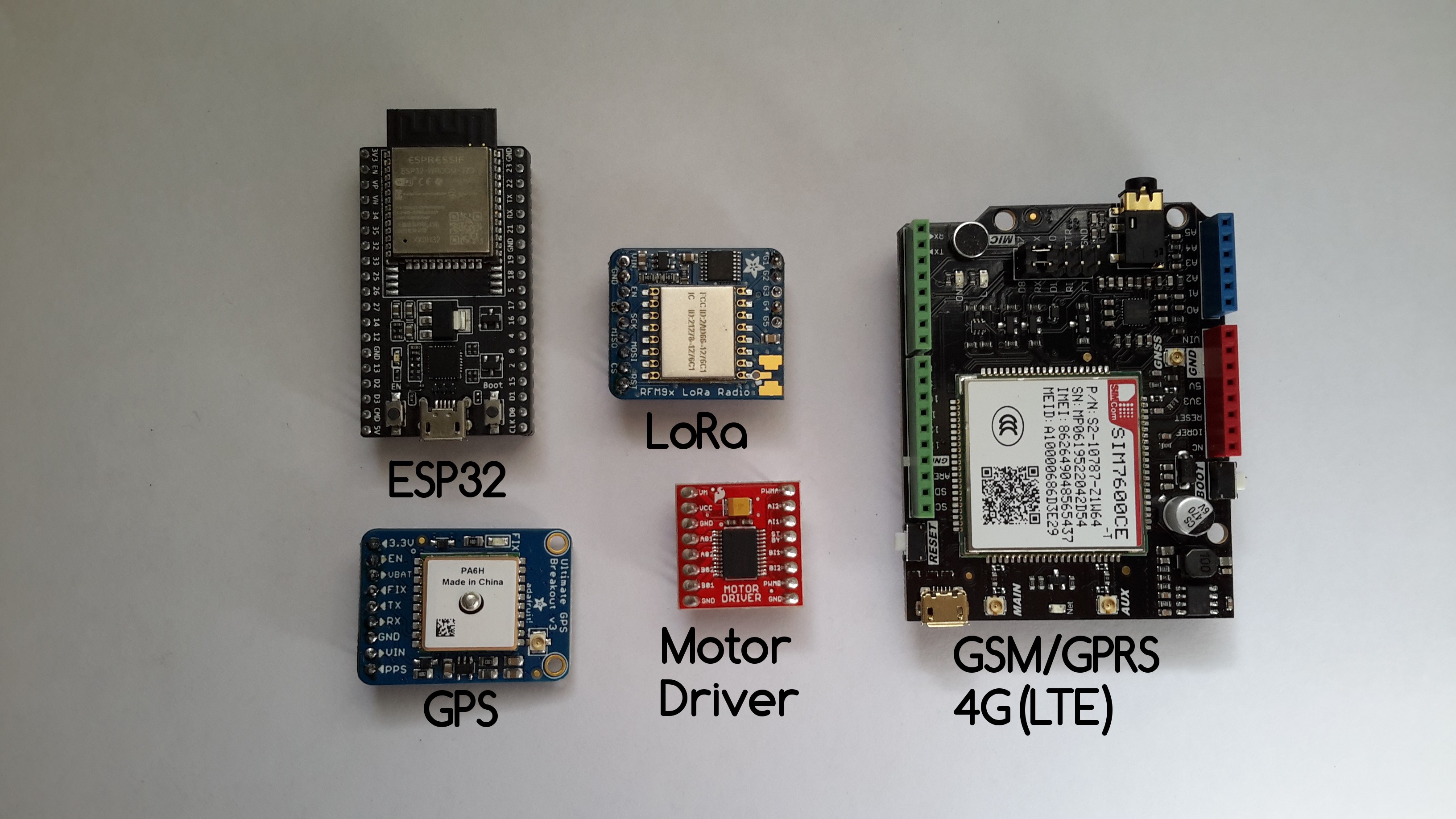
To achieve the position marking of the traps we selected 5 main components:
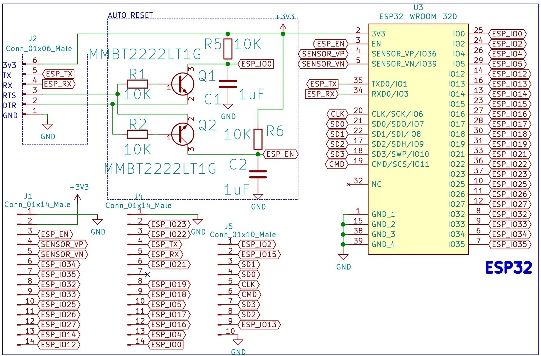
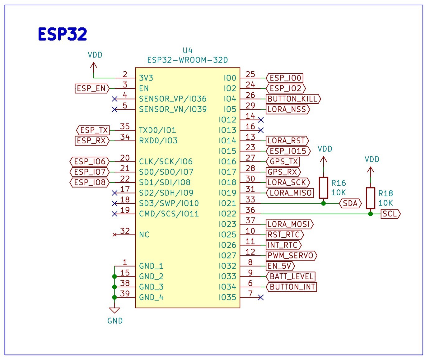
- ESP32-DEVKITC-32D
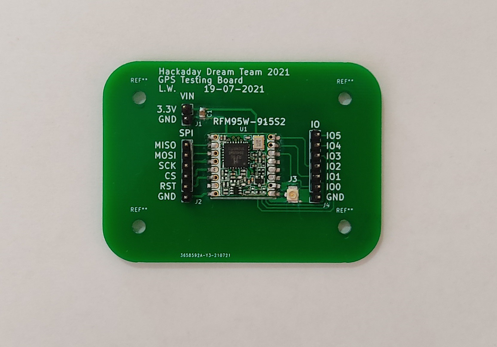
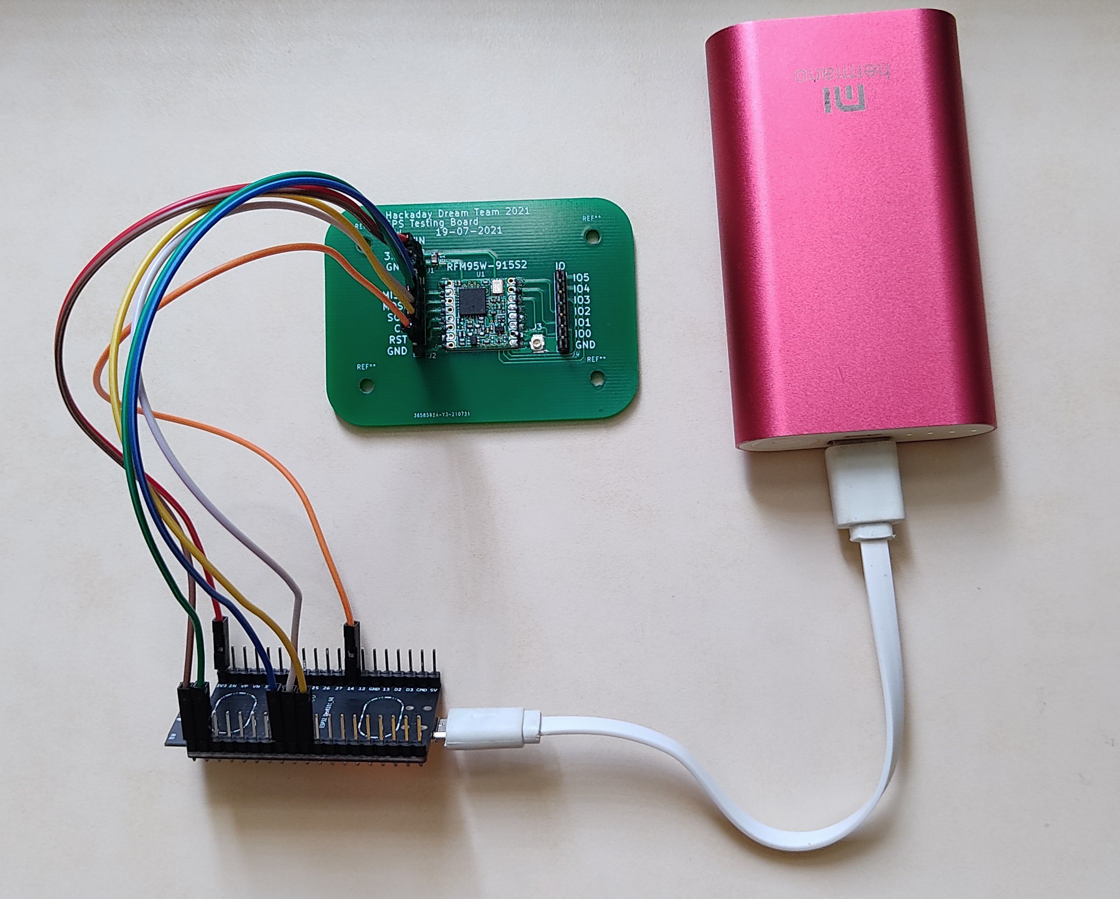
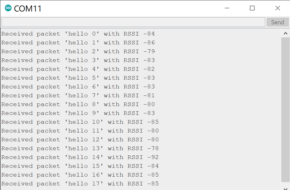
- RFM95W LoRa Radio
- TB6612FNG MOTOR DRIVER BOARD
- Adafruit Ultimate GPS
- SIM7600CE-T 4G(LTE) Arduino Shield
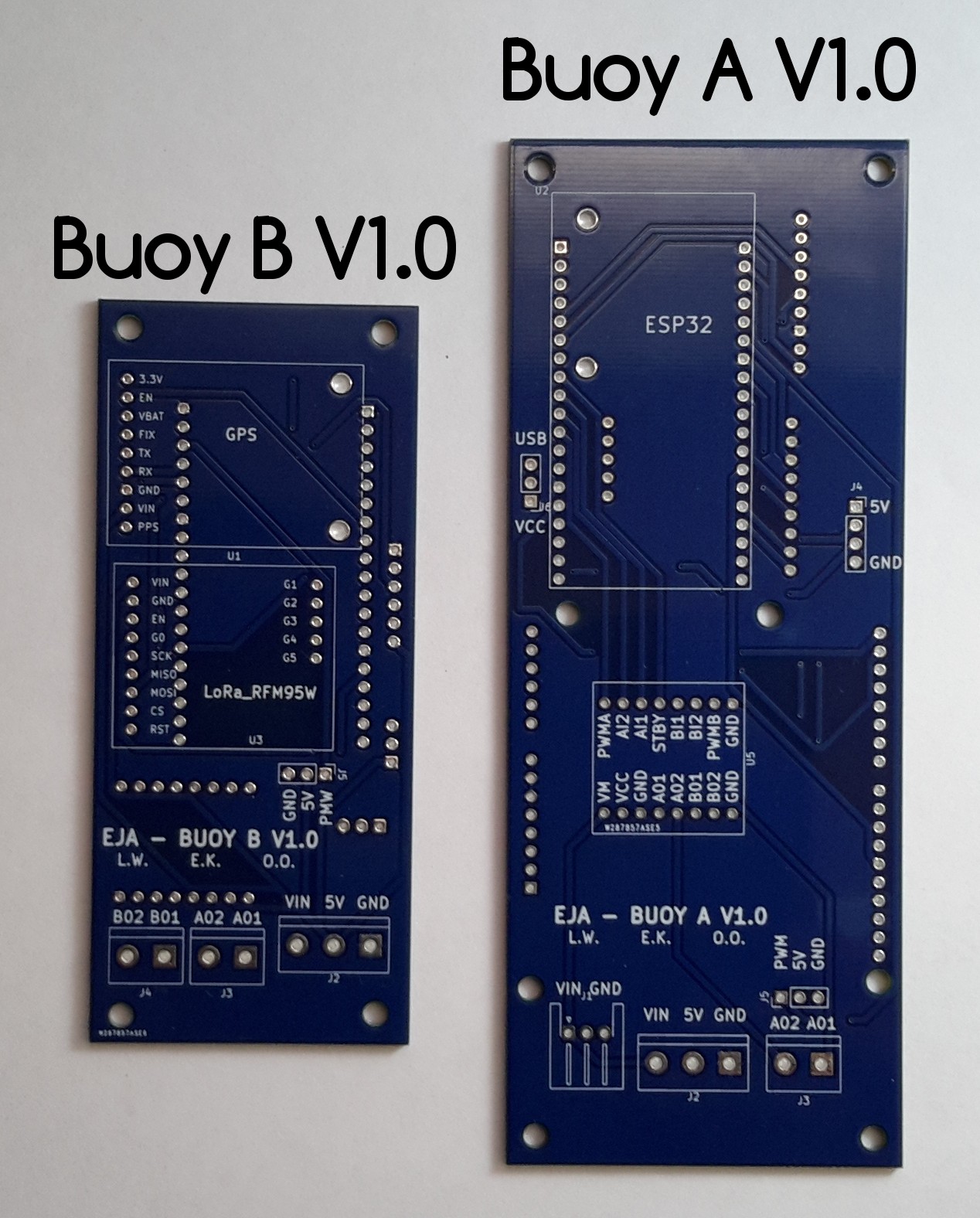
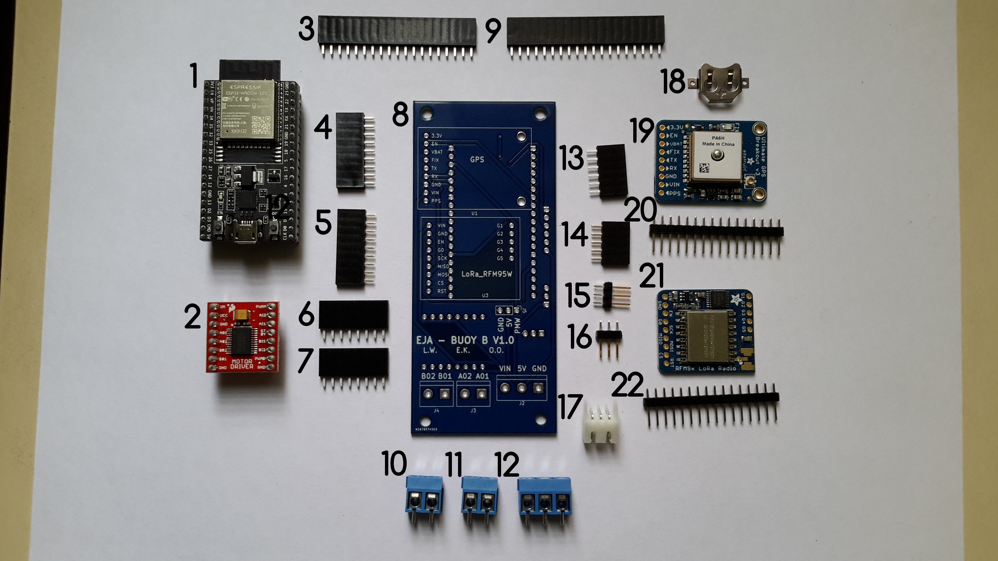
From this main components we designed 2 PCBs: Buoy A V1.0 and Buoy B V1.0.
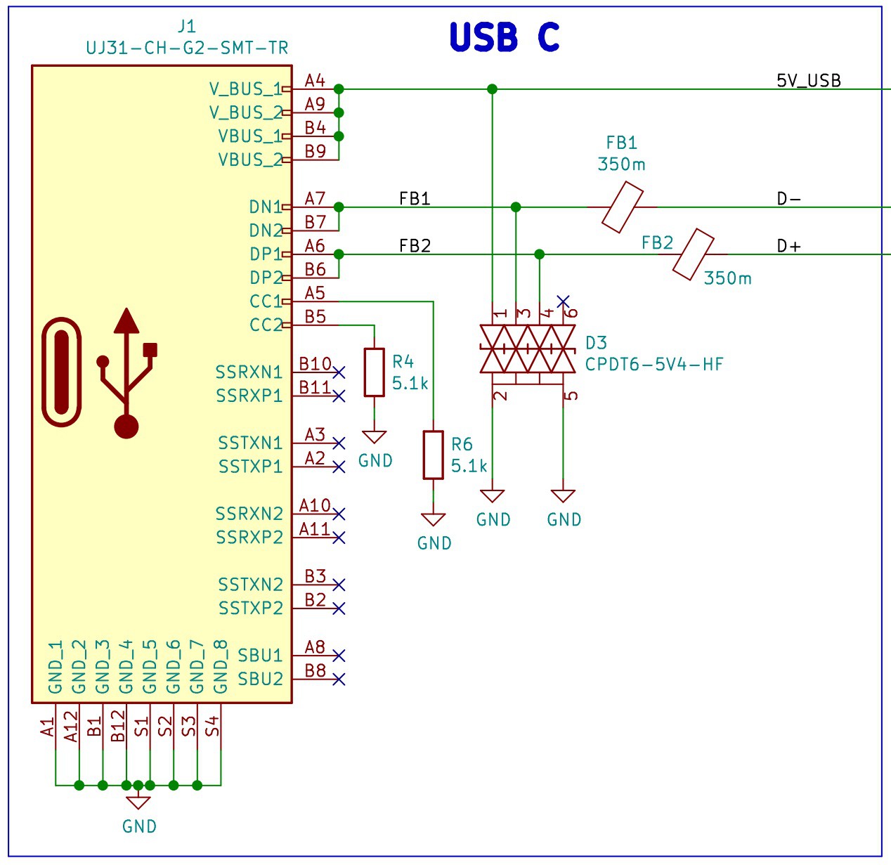
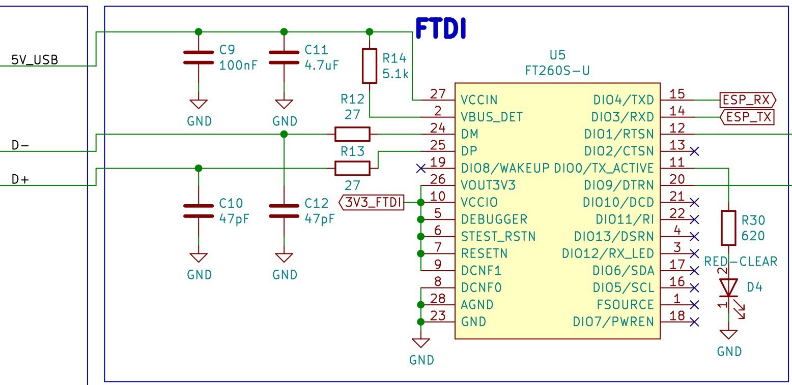
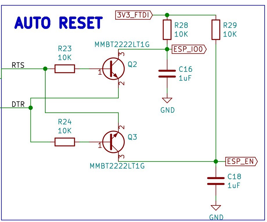
Buoy A V1.0 is a 141.73 mm x 54.86 mm PCB that integrates the 5 main components (ESP32, LoRa, GPS, Motor Driver and GSM/GPRS). Buoy B V1.0 is a 102.46 mm x 44.20 mm PCB that integrates 4 of the main components (ESP32, LoRa, GPS and Motor Driver).
To describe the PCB designs we have prepared the following guides:
- Buoy A - Electronic Design - Github Repository
- Buoy A - Firmware - Github Repository
- Buoy A V1.0 - Schematic and PCB Design
- Buoy A V.10 - Bill of Materials
- Buoy A V1.0 - Assembly
- Buoy A V1.0 - Wiring Diagrams
- Buoy B - Electronic Design - Github Repository
- Buoy B - Firmware - Github Repository
- Buoy B V1.0 - Schematic and PCB Design
- Buoy B V.10 - Bill of Materials
- Buoy B V1.0 - Assembly
- Buoy B V1.0 - Wiring Diagrams
- Buoy A V1.0 and Buoy B V1.0 - Future Improvements
It is possible to adapt more modules/breakout boards to the current designs, there are dedicated connectors that allow it in each board, we have explored the following additions:
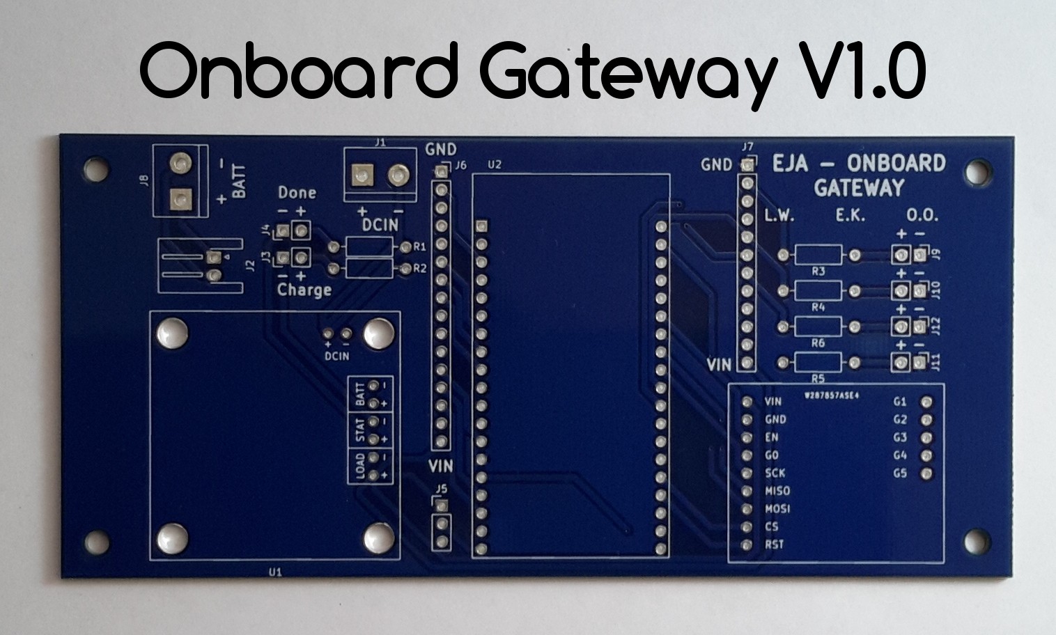
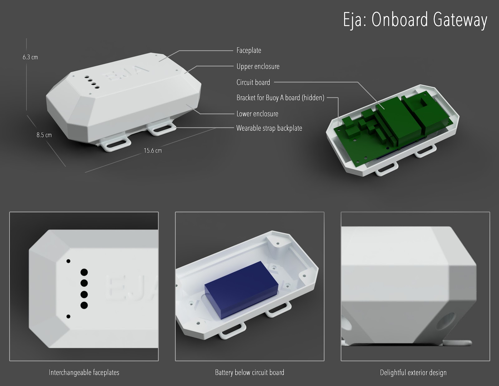
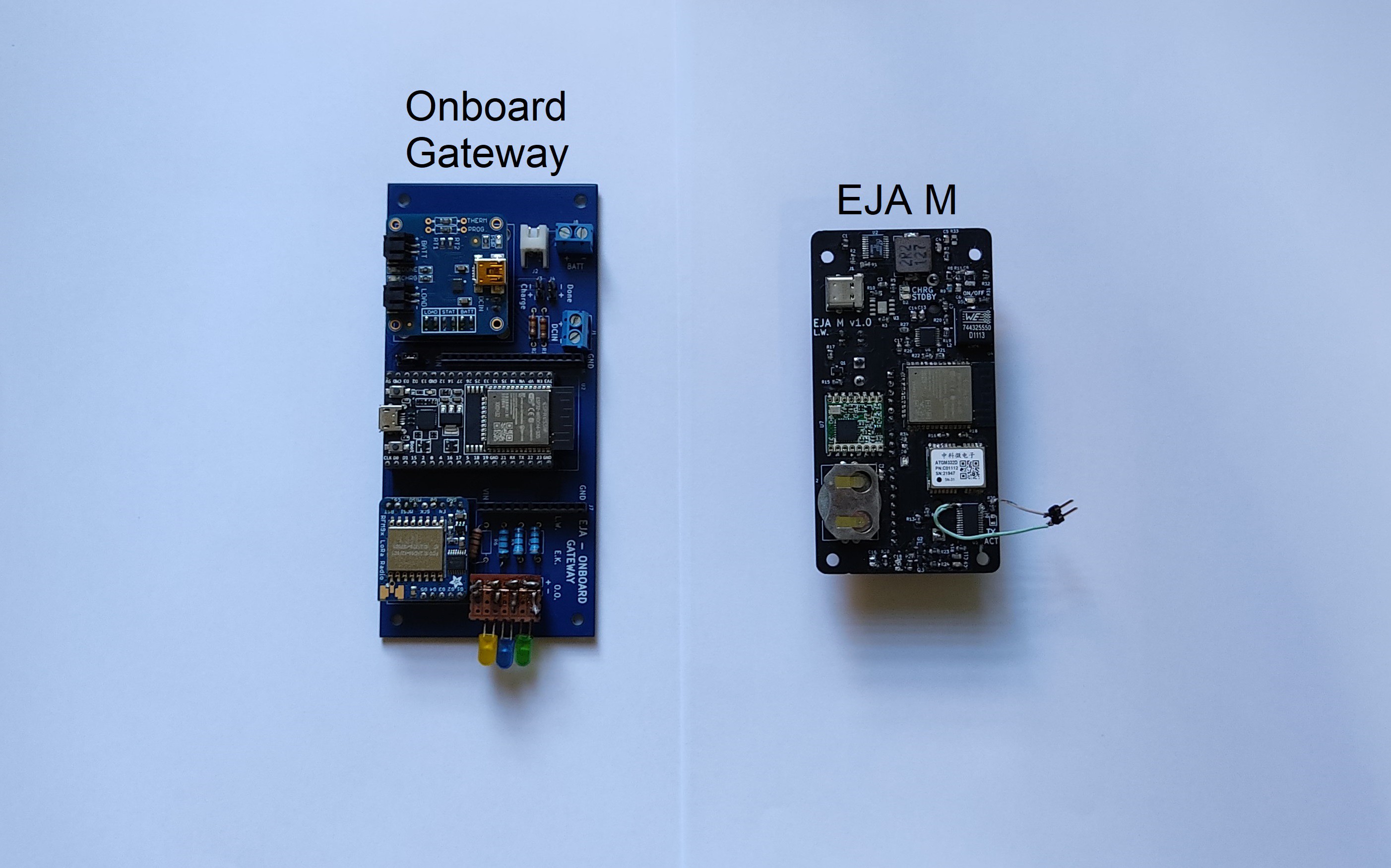
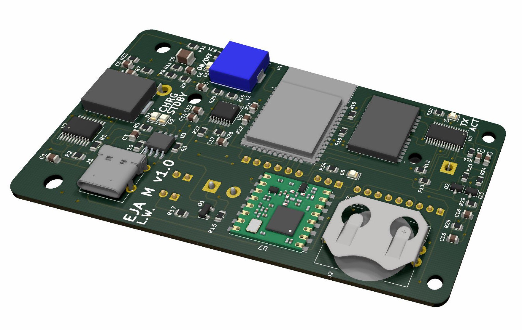
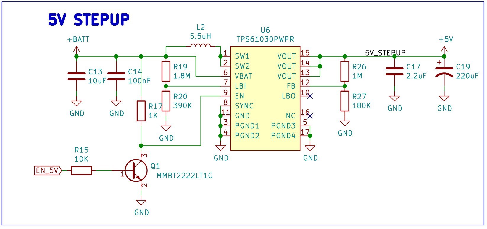
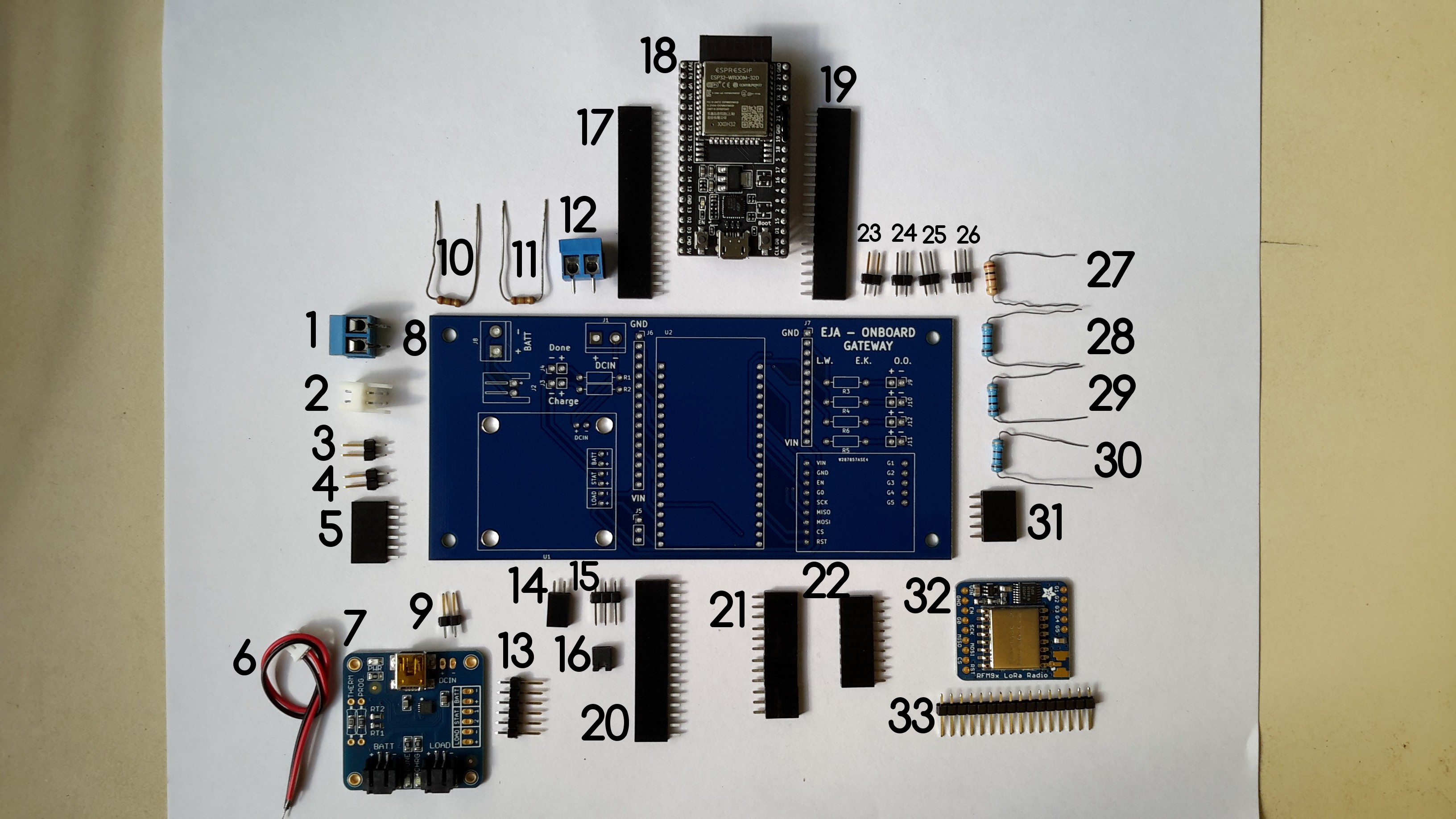
Onboard Gateway
Onboard Gateway is a 134.11 mm x 62.48 mm PCB that is used to communicate with the intelligent buoy and receive the GPS data. The design integrates 3 main components:
From this main components we designed the PCB: Onboard Gateway V1.0 (134.11 mm x 62.48 mm).
To describe the PCB design we have prepared the following guides:
- Onboard Gateway - Electronic Design - Github Repository
- Onboard Gateway - Firmware - Github Repository
- Onboard Gateway V1.0 - Schematic and PCB Design
- Onboard Gateway V.10 - Bill of Materials
- Onboard Gateway V1.0 - Assembly
- Onboard Gateway V1.0 - Wiring Diagrams
- Onboard Gateway V1.0 - Future Improvements
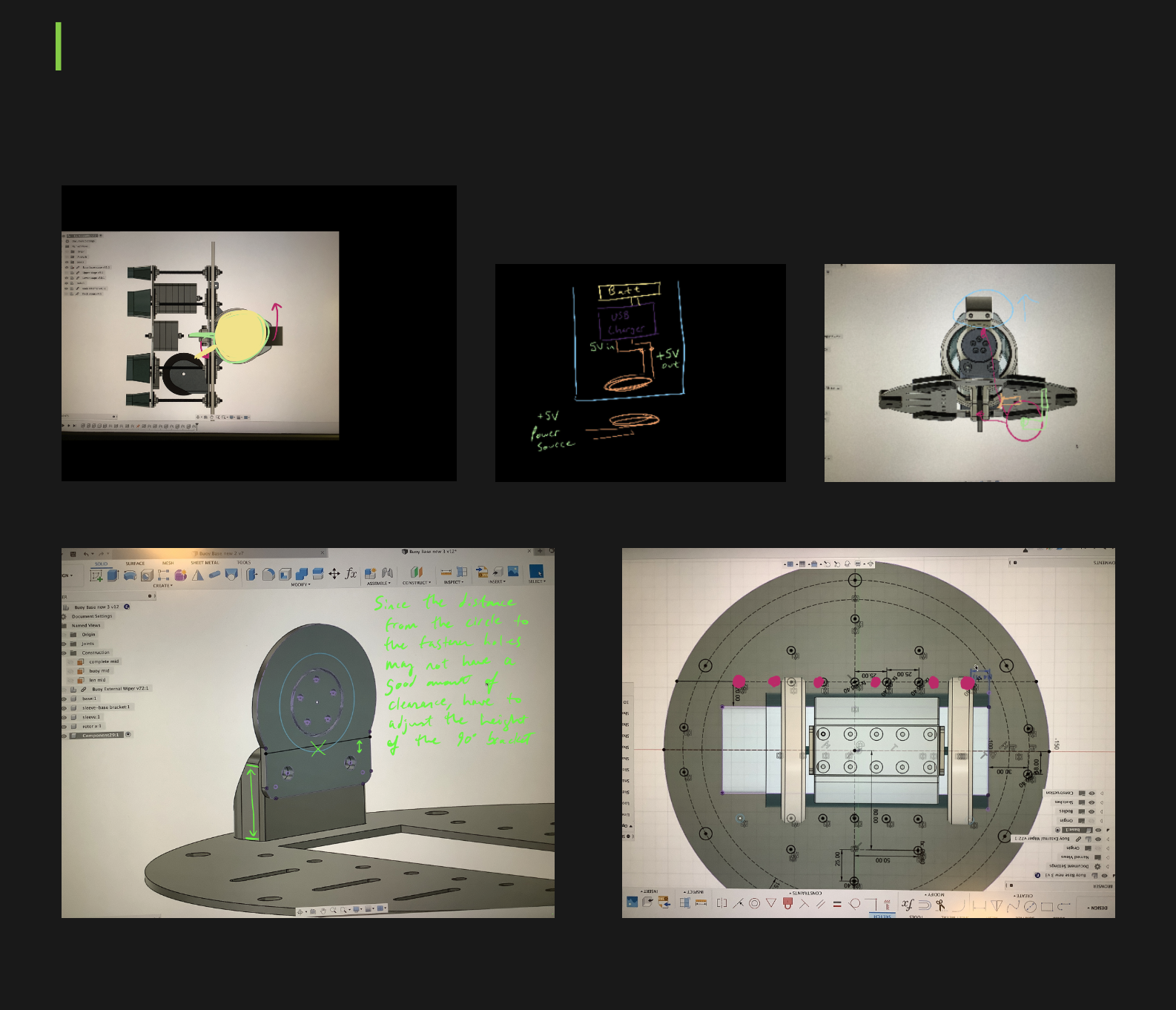
Mechanical
--- Version 2 ---
3D viewer: https://a360.co/38TzX7L
See all of the files on the Github repository (including bill of materials (BOM), and production plan)
--- Version 1 ---
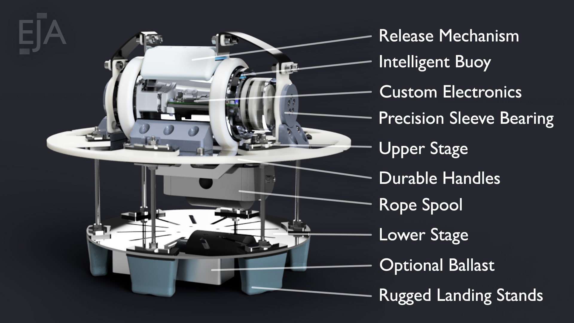
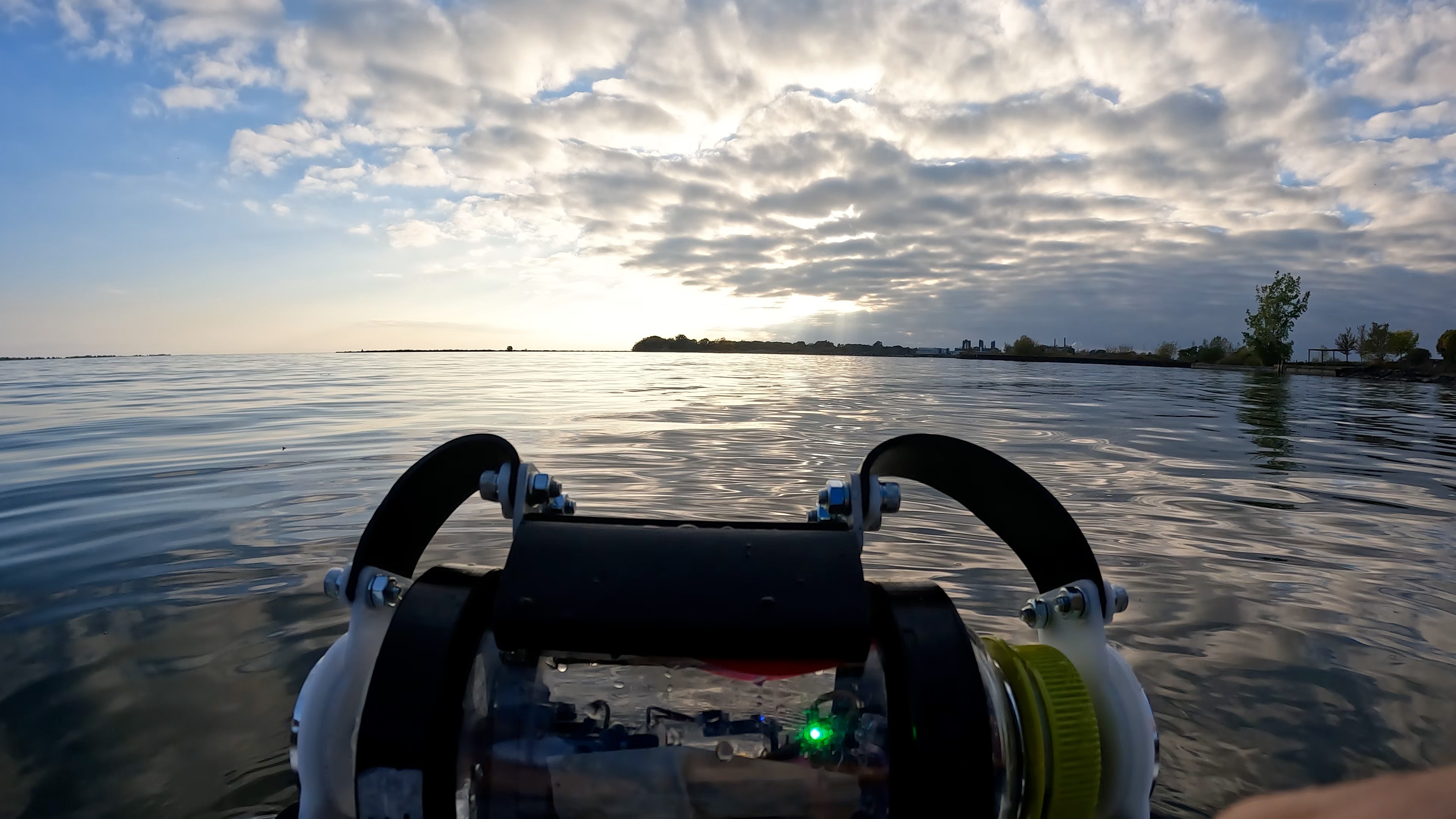
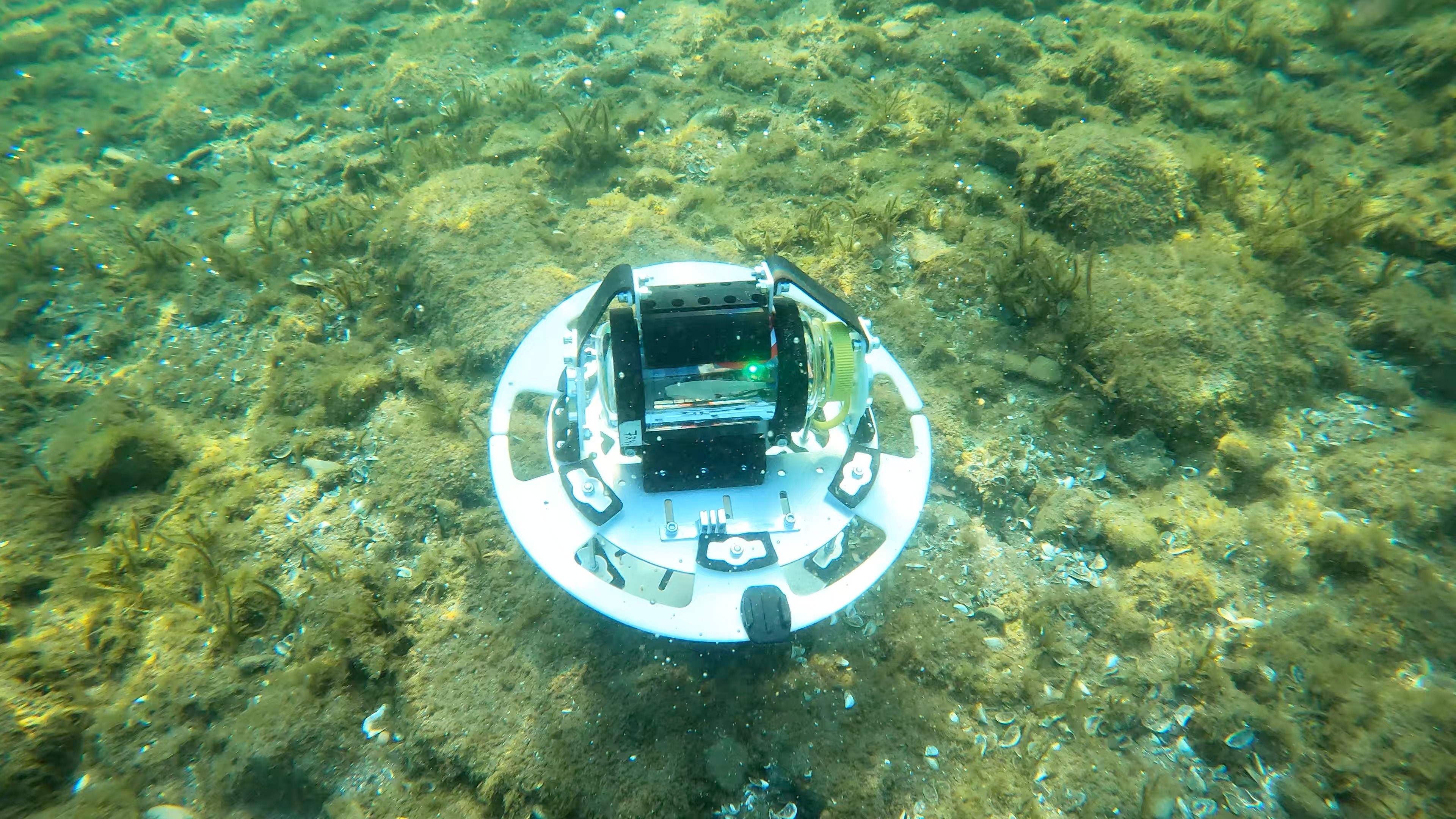
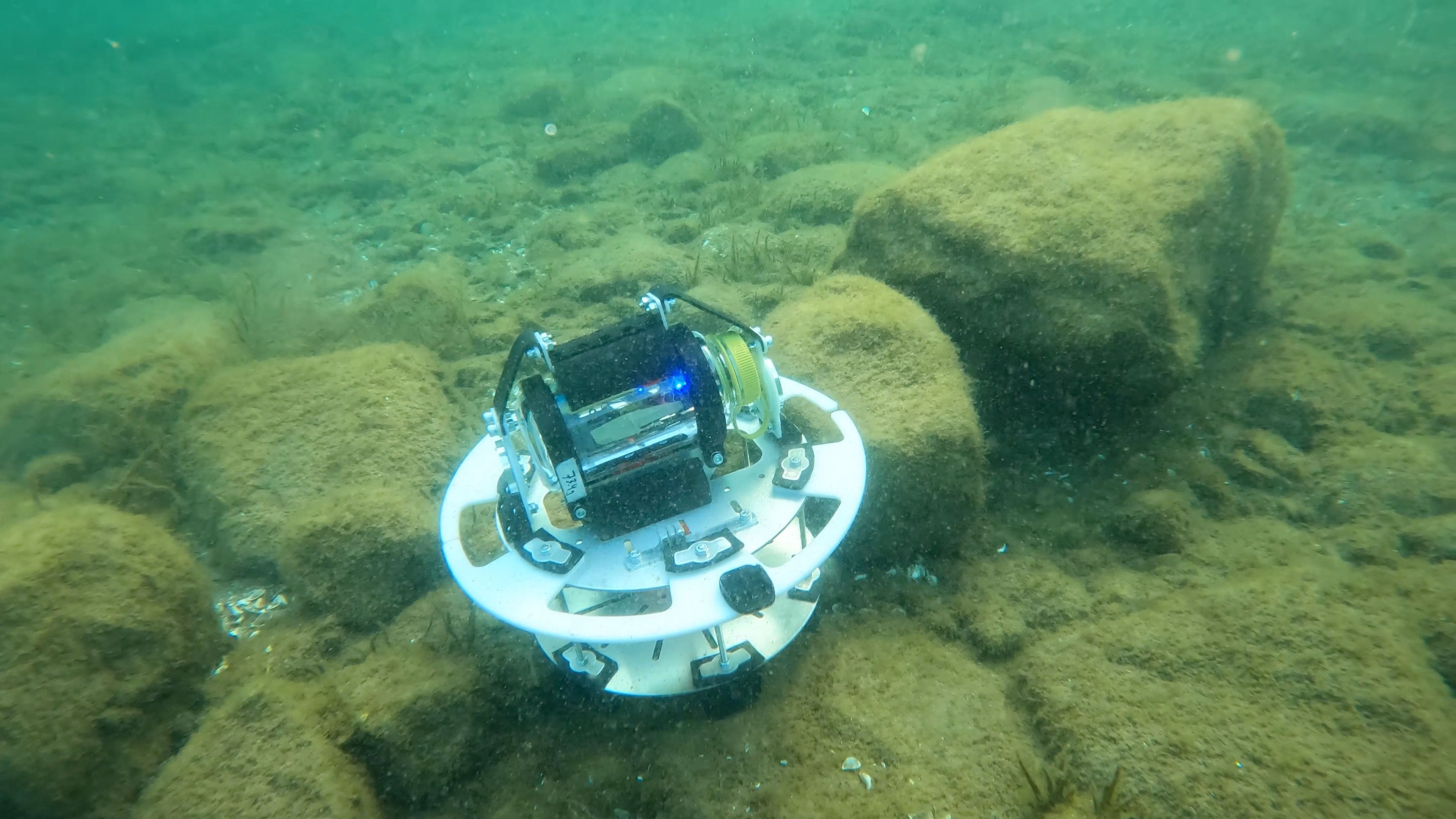
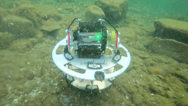
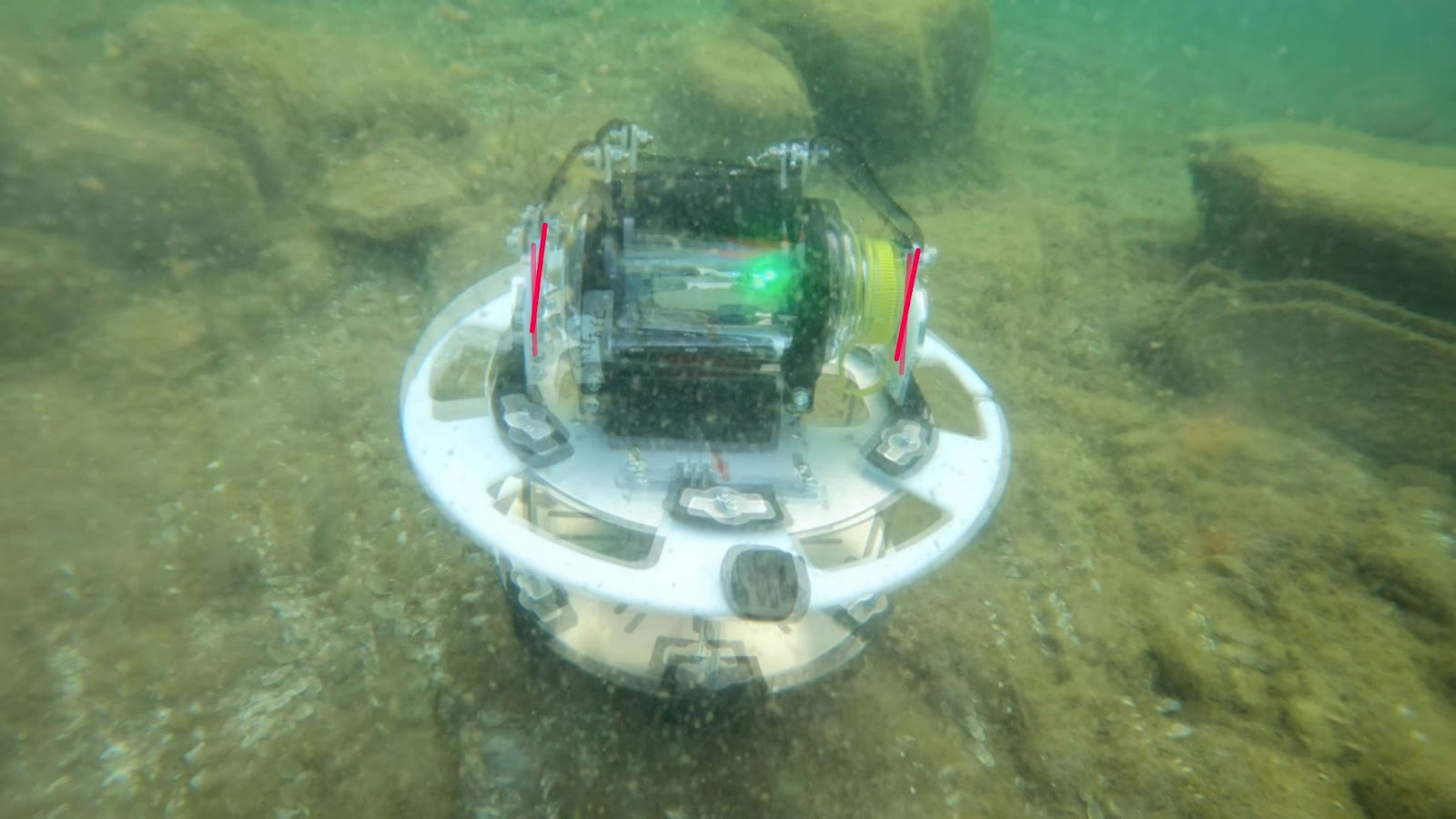
The Eja ropeless gear system consists of three parts: Release Mechanism, Intelligent Buoy, and Onboard Gateway. Here are the mechanical design specifications for each, also available as a pdf here.
Release Mechanism
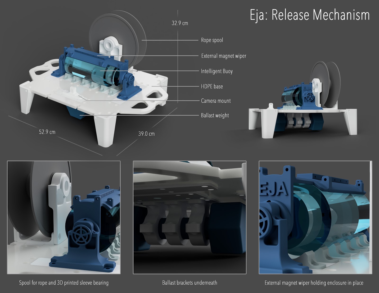

3D viewer: https://a360.co/3msDSha
Intelligent Buoy

3D viewer: https://a360.co/3hJjc0R
Onboard Gateway
3D viewer: https://a360.co/32DGUHE
For additional information relating to the Bill of Materials and the Parametric Design, please see this project log: Mechanical Design Specifications.
All of the 3D print files, .STEP assembly, and more can be found on Github here.


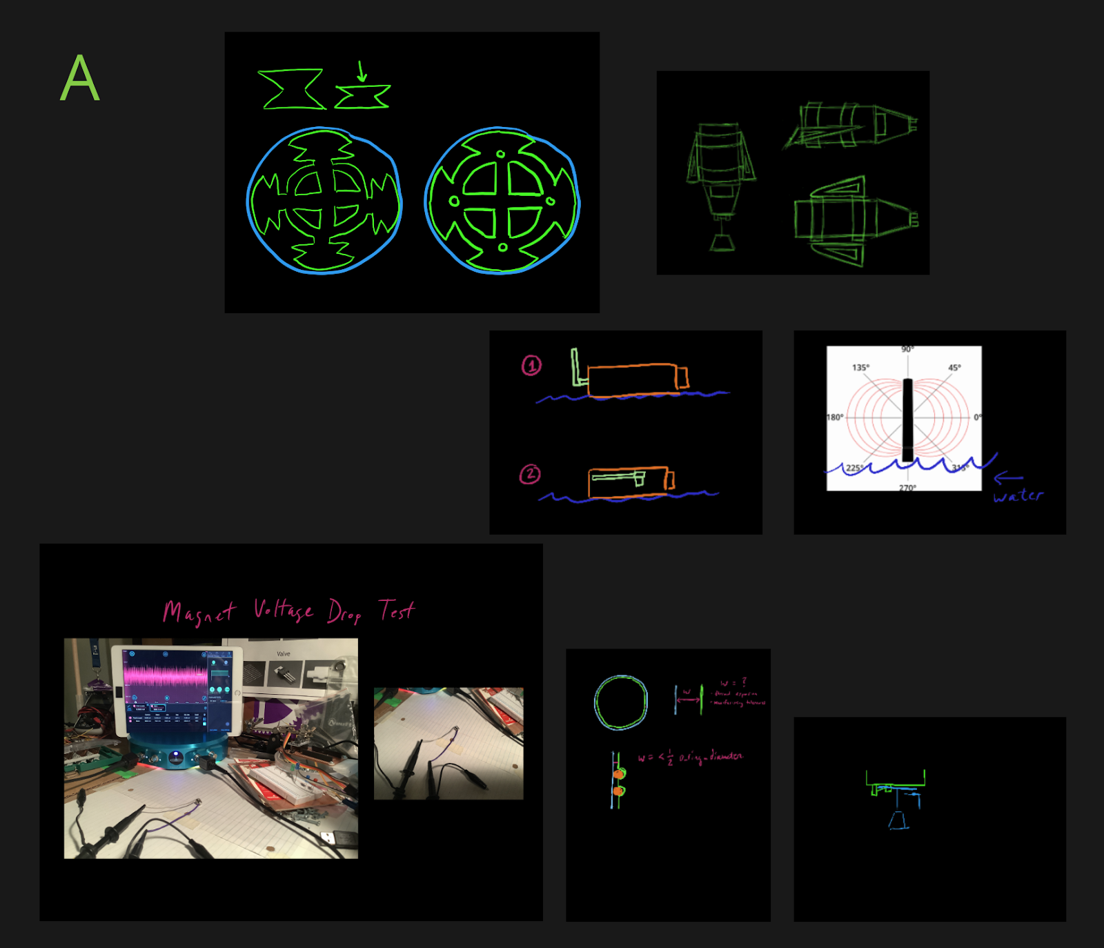 A: The beginning, getting oriented (see the buoy with different antenna orientations). Different ideas.
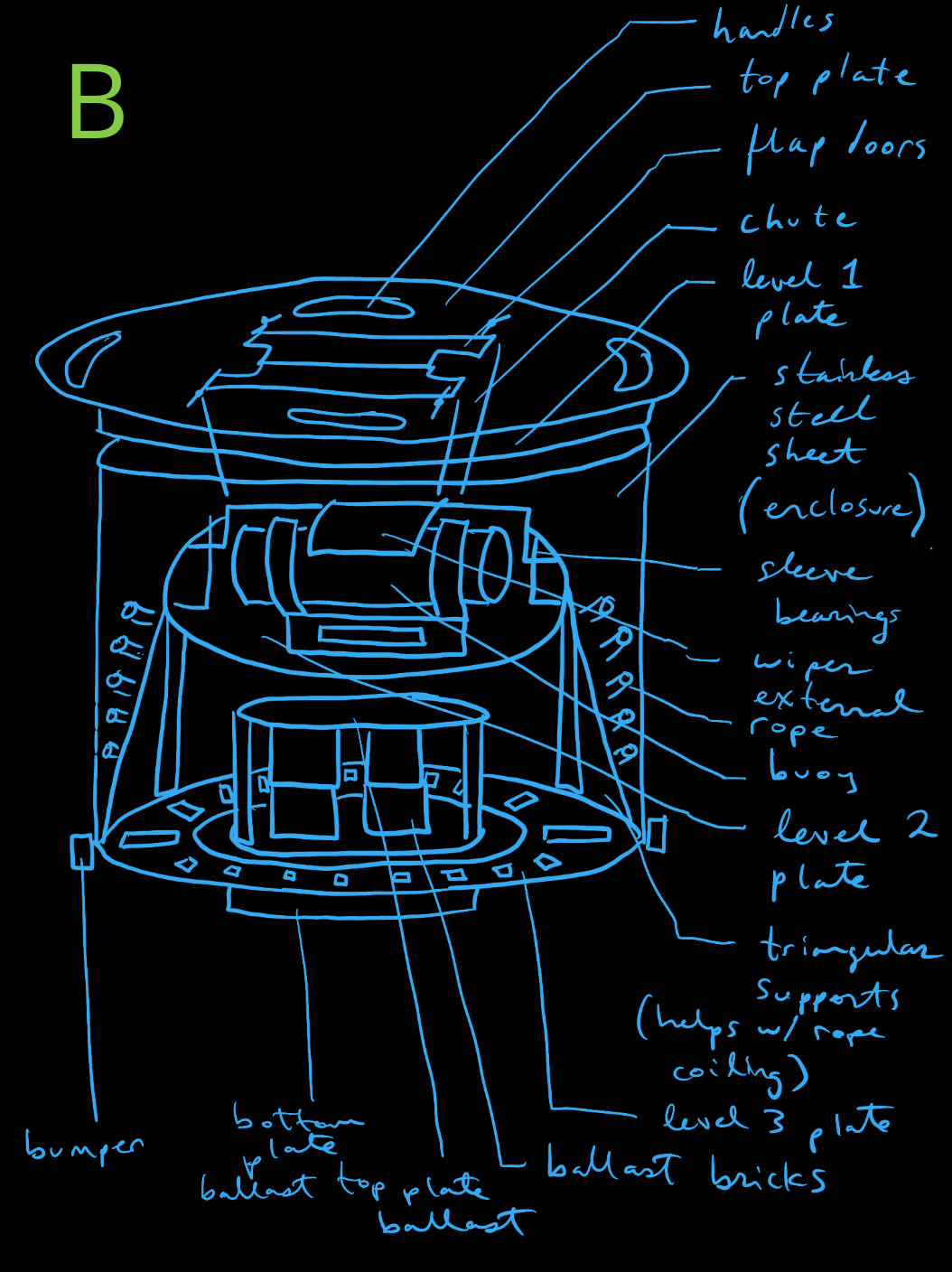 B: The somewhat finalized concept idea. This one had too many moving parts though. The commonality is the stacked stages.
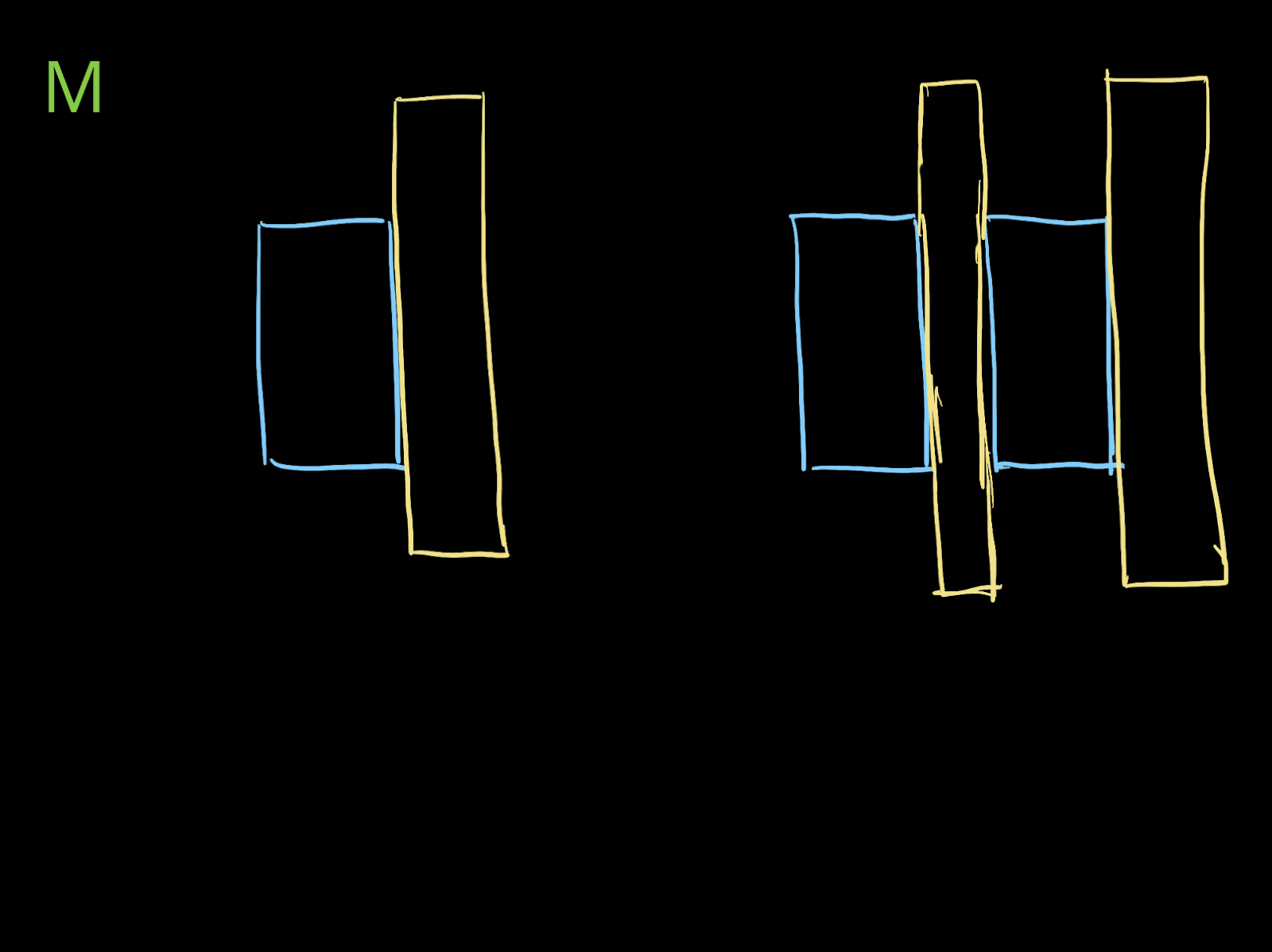
 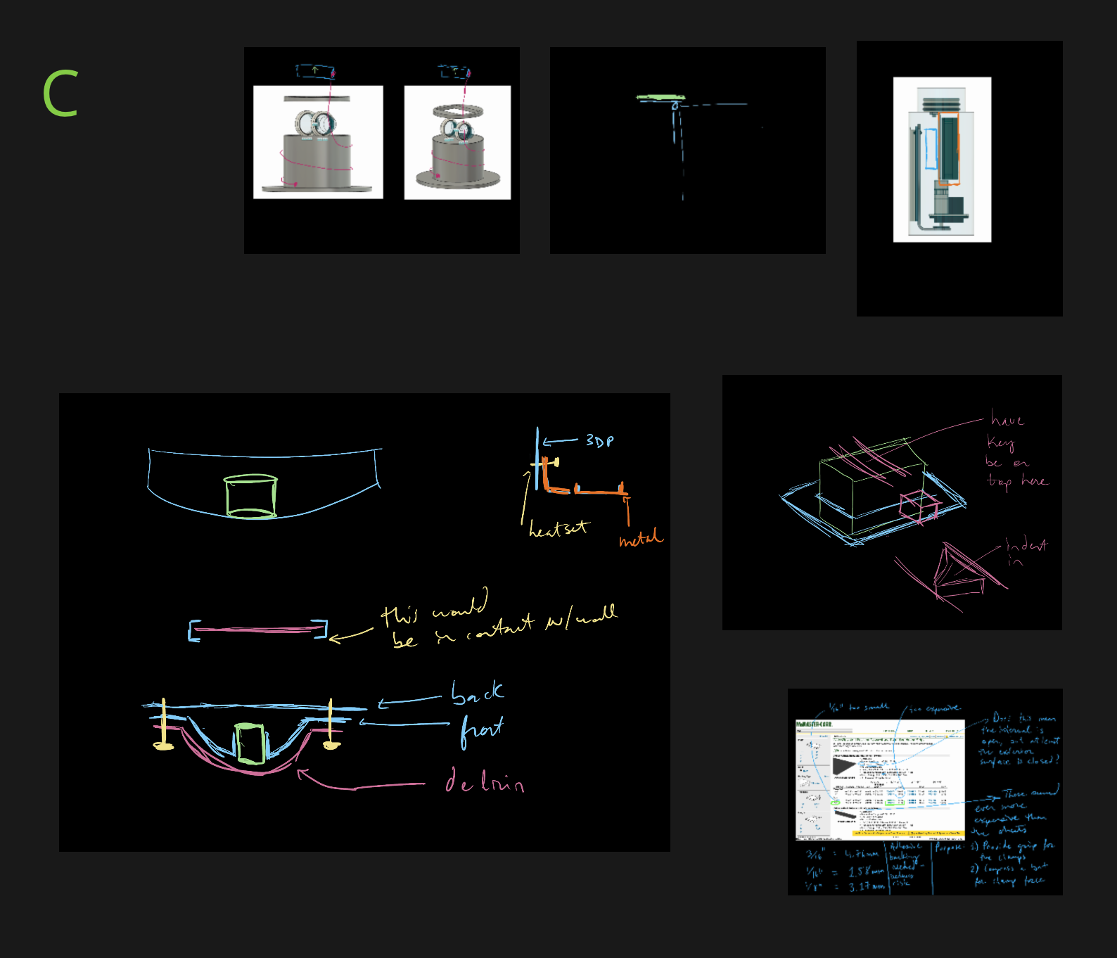 C: Wiper magnets being closer and with less friction with a thin delrin sheet. This idea was later scrapped since Giovanni came up with a great solution - two low-profile ‘rails’ that the wiper glides on - reducing scratches, minimizing contact area, and less materials!
 D: A lot of other ropeless fishing system designs use rope bags. What if there was a way to coil the rope? If it’s conical shaped, this would reduce tangling when coiling… however, if it is conical shaped, this means that the loading and landing orientation is 180 degrees flipped. This idea was scrapped because the centre of mass was at the top (for landing state, if it would even land like that).
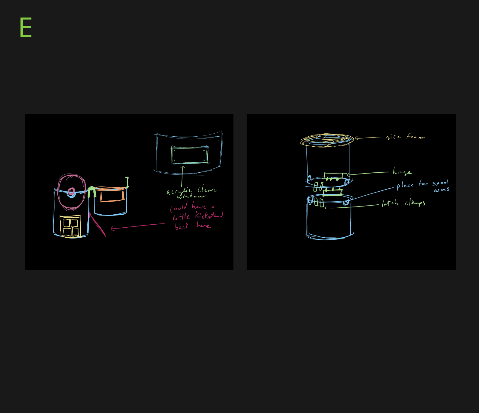 E: Here was another concept. It is a tube cut in half with latch clamps. This idea just didn’t work logistically, and it seems like it would be cumbersome to try to reload the spool afterwards.


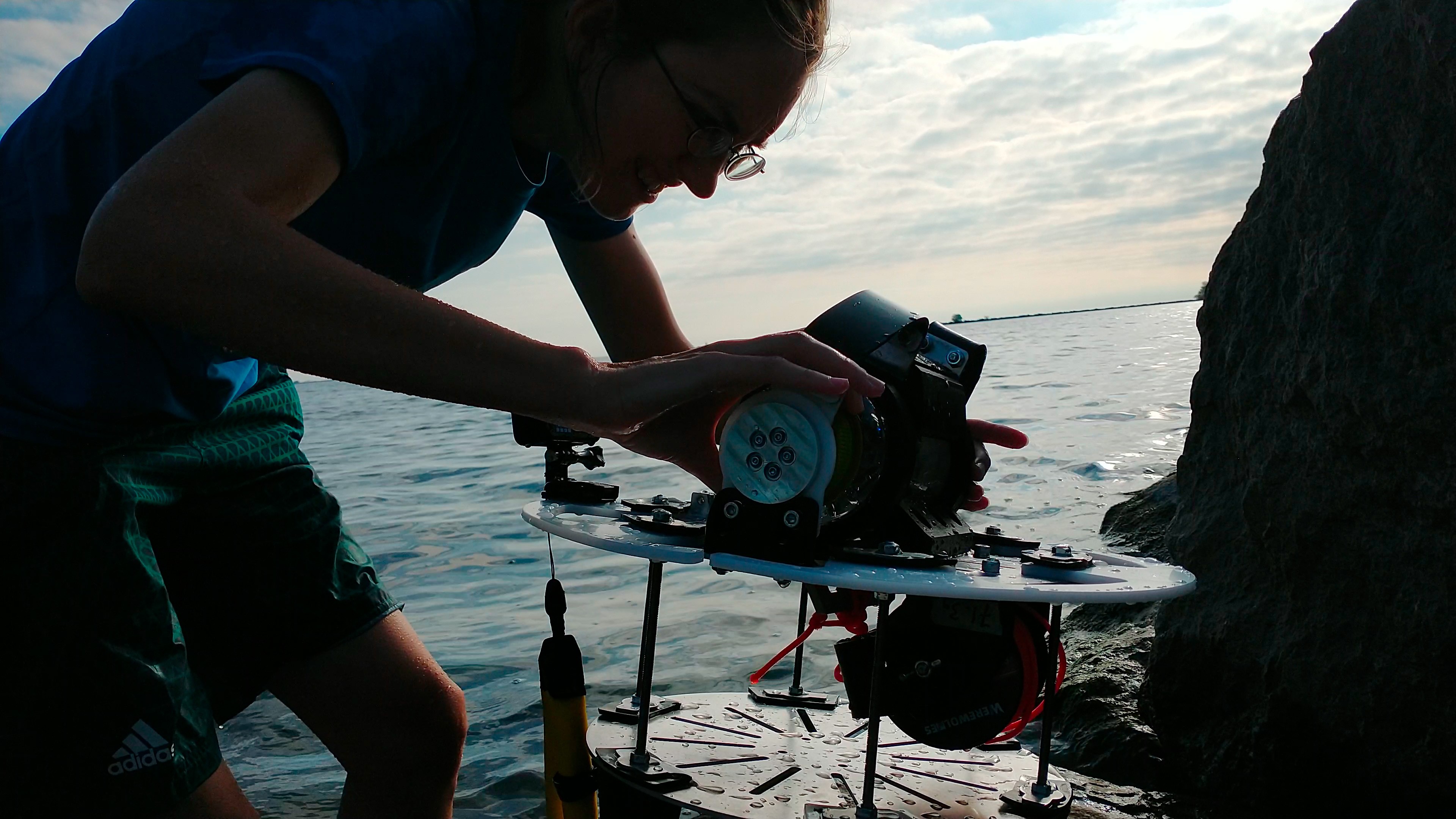
 J: Electronics integration review with Leo! This was a great way to point out areas of concern on the integration side.


 Alex Muir
 Nick van de Giesen
 ifthekhar ahammad
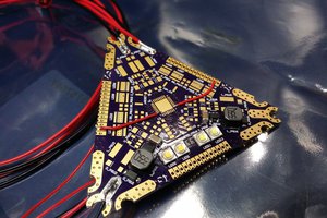
 slisgrinder
Hi guys, what an incredible project, I understand you have been working for a couple of months now, hopefully you can share some progress. I'm an embedded developer and I would like to see how this project has been tackled, but I see that you haven't published anything about it yet, my notes include:
1. What tools are you using? FreeRTOS?
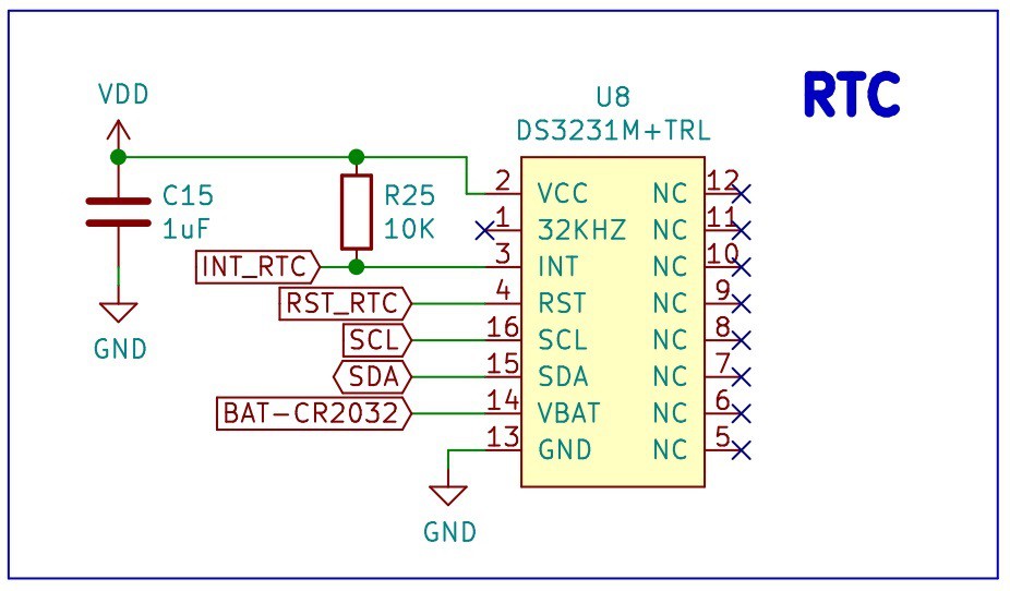
2. How do you manage the offline behavior? I checked some hardware descriptions and I don't see any RTC, do you have any different idea to address this issue maybe by software? If you are using it, how is the process of initializing the device to take the correct time reference in your code? Without a doubt being in the middle of the ocean without an internet connection is a big problem.
3. Will you publish your work opensource? with some repository?
I hope you can answer my questions and I wish you the best of success, waiting to see your results!